


POWER AMPLIFIER
Owner’s Manual
E
FCC INFORMATION (U.S.A.)
1.IMPORTANT NOTICE: DO NOT MODIFY THIS UNIT! This product, when installed as indicated in the instructions contained in this manual, meets FCC requirements. Modifications not expressly approved by Yamaha may void your authority, granted by the FCC, to use the product.
2.IMPORTANT: When connecting this product to accessories and/or another product use only high quality shielded cables. Cable/s supplied with this product MUST be used. Follow all installation instructions. Failure to follow instructions could void your FCC authorization to use this product in the USA.
3.NOTE: This product has been tested and found to comply with the requirements listed in FCC Regulations, Part 15 for Class “B” digital devices. Compliance with these requirements provides a reasonable level of assurance that your use of this product in a residential environment will not result in harmful interference with other electronic devices. This equipment generates/uses radio frequencies and, if not installed and used according to the instructions found in the users manual, may cause interference harmful to the operation of other electronic devices. Compliance with FCC regulations does not guarantee that interference will not occur in all installations. If this product is found to be the source of interference, which can be determined by turning the unit “OFF” and “ON”, please try to eliminate the problem by using one of the following measures: Relocate either this product or the device that is being affected by the interference. Utilize power outlets that are on different branch (circuit breaker or fuse) circuits or install AC line filter/s. In the case of radio or TV interference, relocate/reorient the antenna. If the antenna lead-in is 300 ohm ribbon lead, change the lead-in to coaxial type cable. If these corrective measures do not produce satisfactory results, please contact the local retailer authorized to distribute this type of product. If you can not locate the appropriate retailer, please contact Yamaha Corporation of America, Electronic Service Division, 6600 Orangethorpe Ave, Buena Park, CA 90620
The above statements apply ONLY to those products distributed by Yamaha Corporation of America or its subsidiaries.
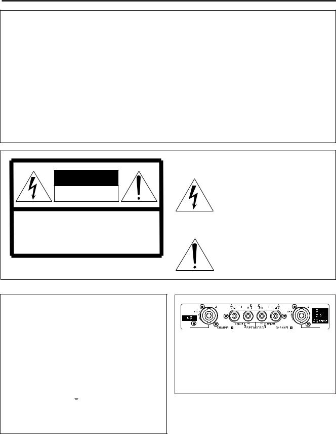
CAUTION
RISK OF ELECTRIC SHOCK
DO NOT OPEN
CAUTION: TO REDUCE THE RISK OF ELECTRIC SHOCK, DO NOT REMOVE COVER (OR BACK). NO USER-SERVICEABLE PARTS INSIDE. REFER SERVICING TO QUALIFIED SERVICE PERSONNEL.
The above warning is located on the top of the unit.
• Explanation of Graphical Symbols
The lightning flash with arrowhead symbol within an equilateral triangle is intended to alert the user to the presence of uninsulated “dangerous voltage” within the product’s enclosure that may be of sufficient magnitude to constitute a risk of electric shock to persons.
The exclamation point within an equilateral triangle is intended to alert the user to the presence of important operating and maintenance (servicing) instructions in the literature accompanying the product.
WARNING: THIS APPARATUS MUST BE EARTHED
IMPORTANT
THE WIRES IN THIS MAINS LEAD ARE COLOURED IN ACCORDANCE WITH THE FOLLOWING CODE:
GREEN-AND-YELLOW : EARTH
BLUE : NEUTRAL
BROWN : LIVE
As the colours of the wires in the mains lead of this apparatus may not correspond with the coloured markings identifying the terminals in your plug, proceed as follows:
The wire which is coloured GREEN and YELLOW must be connected to the terminal in the plug which is marked by the letter E or by the safety earth symbol  or coloured GREEN and YELLOW.
The wire which is coloured BLUE must be connected to the terminal which is marked with the letter N or coloured BLACK.
The wire which is coloured BROWN must be connected to the terminal which is marked with the letter L or coloured RED.
*This applies only to products distributed by YAMAHA KEMBLE MUSIC (U.K.) LTD.
European Specifications Only
This  mark indicates a dangerous electrically live terminal.
When connecting an external wire to this terminal, it is necessary either to have “a person who have received appropriate guidance on handling” make the connection or to use leads or a cord that have been manufactured in such a way that the connection can be made simply and without problem.
2

Precautions
WARNING
Installation |
Operation |
•Connect this unit’s power cord only to an AC outlet of the type stated in this Owner’s Manual or as marked on the unit. Failure to do so is a fire and electrical shock hazard.
•Do not allow water to enter this unit or allow the unit to become wet. Fire or electrical shock may result.
•Do not place a container with liquid or small metal objects on top of this unit. Liquid or metal objects inside this unit are a fire and electrical shock hazard.
•Do not place heavy objects, including this unit, on top of the power cord. A damaged power cord is a fire and electrical shock hazard. In particular, be careful not to place heavy objects on a power cord covered by a carpet.
•Use only the included power cord for this unit. Using other types may be a fire and electrical shock hazard.
•Do not scratch, bend, twist, pull, or heat the power cord. A damaged power cord is a fire and electrical shock hazard.
•Do not remove the unit’s cover. You could receive an electrical shock. If you think internal inspection, maintenance, or repair is necessary, contact your dealer.
•Do not modify the unit. Doing so is a fire and electrical shock hazard.
•If lightning begins to occur, turn off the power switch of the unit as soon as possible, and unplug the power cable plug from the electrical outlet.
•If there is a possibility of lightning, do not touch the power cable plug if it is still connected. Doing so may be an electrical shock hazard.
In case an abnormality occurs during operation
•If the power cord is damaged (i.e., cut or a bare wire is exposed), ask your dealer for a replacement. Using the unit with a damaged power cord is a fire and electrical shock hazard.
•Should this unit be dropped or the cabinet be damaged, turn the power switch off, remove the power plug from the AC outlet, and contact your dealer. If you continue using the unit without heeding this instruction, fire or electrical shock may result.
•If you notice any abnormality, such as smoke, odor, or noise, or if a foreign object or liquid gets inside the unit, turn it off immediately. Remove the power cord from the AC outlet.
Consult your dealer for repair. Using the unit in this condition is a fire and electrical shock hazard.
3

CAUTION
Installation
•Keep this unit away from the following locations:
-Locations exposed to oil splashes or steam, such as near cooking stoves, humidifiers, etc.
-Unstable surfaces, such as a wobbly table or slope.
-Locations exposed to excessive heat, such as inside a car with all the windows closed, or places that receive direct sunlight.
-Locations subject to excessive humidity or dust accumulation.
•Hold the power cord plug when disconnecting it from an AC outlet. Never pull the cord. A damaged power cord is a potential fire and electrical shock hazard.
•Do not touch the power plug with wet hands. Doing so is a potential electrical shock hazard.
•This unit has ventilation holes at the rear to prevent the internal temperature rising too high. Do not block them. Blocked ventilation holes are a fire hazard.
•To relocate the unit, turn the power switch off, remove the power plug from the AC outlet, and remove all connecting cables. Damaged cables may cause fire or electrical shock.
•Allow enough free space around the unit for normal ventilation. This should be: 5 cm at the sides, 10 cm behind, and 10 cm above.
For normal ventilation during use, remove the rear of the rack or open a ventilation hole.
If the airflow is not adequate, the unit will heat up inside and may cause a fire.
•To mount several of these units in an EIA-compliant rack, refer to the rack mounting instructions on page 10.
Operation
•Use only speaker cables when connecting speakers to amplifier outputs. Using other types of cables is a fire hazard.
•Do not use this amplifier for any purpose other than driving loudspeakers.
PRECAUTIONS FOR OPERATION |
– FOR CORRECT OPERATION – |
Connector pin assignments
•XLR-type connectors are wired as follows: pin 1: ground, pin 2: hot (+), and pin 3: cold (–).
Influence on cell phone usage
•Using a cell phone (mobile telephone) near this unit may induce noise. If noise occurs, use the telephone away from the unit.
4

Introduction
Thank you for purchasing a Yamaha PC9500N, or PC4800N Series Power Amplifier.
The PC Series of power amplifiers was developed from Yamaha’s wealth of experience in building PA equipment and its tradition of careful attention to every detail of circuit design. These power amplifiers feature high power and superb quality together with superior reliability and stability, guaranteeing the highest possible audio performance.
Main features include
•Three modes are provided to support a broad range of applications: STEREO mode which can be driven by two independent sources, PARALLEL mode in which a monaural source drives both channels, and BRIDGE mode in which the two internal amps function as a single mono amp.
•Balanced XLR connector and Euroblock connector inputs, and Speakon connector and fiveway binding post outputs are provided.
•A high pass filter switch that cuts frequencies below 40 Hz, and detented attenuators and level meters for channels A and B are provided.
•Metering and indicators include easily visible two-channel level meters, a PROTECTION indicator that shows the state of various protection systems (power on/off detection, output protection, DC detection), a TEMP indicator that indicates heat sink overheating, and a REMOTE indicator that indicates the external remote status.
•Variable-speed, low-noise cooling fan system ensures high reliability even under the most demanding conditions.
This Owner’s Manual applies to the PC9500N and PC4800N power amplifier. In order to take full advantage of your power amplifier and enjoy long and trouble-free operation, please read this Owner’s Manual carefully before using your Power Amplifier.
Contents |
|
Introduction ............................................................... |
5 |
Controls and Functions ............................................. |
6 |
Front Panel .......................................................... |
6 |
Rear Panel ........................................................... |
7 |
Speaker connections ........................................... |
8 |
Connection ................................................................ |
9 |
Using a Euroblock connector ............................... |
9 |
Speaker Connection ............................................ |
9 |
Air Flow ................................................................... |
10 |
Rack Mounting ........................................................ |
10 |
Specifications .......................................................... |
11 |
General Specifications ....................................... |
11 |
Block Diagram ................................................... |
12 |
Dimensions ........................................................ |
13 |
Troubleshooting ...................................................... |
14 |
Performance graph ................................................. |
14 |
5
 Loading...