


POWER AMPLIFIER
Owner’s Manual
Mode d’emploi
Bedienungsanleitung
Manual de instrucciónes
|
|
A |
CLIP |
|
B |
TEMP |
|
SIGNAL |
|
|
|
|
15 |
|
|
15 |
|
PROTECTION |
20 |
|
20 |
||
|
|
|
|||
POWER |
25 |
10 |
25 |
|
10 |
|
|
||||
|
30 |
6 |
30 |
|
6 |
|
|
|
|
||
|
40 |
3 |
40 |
|
3 |
ON OFF |
∞ |
0 |
–dB |
∞ |
0 |
|
|
|
|
|
|
EEEngine
M

Introduction
Thank you for purchasing a Yamaha P4500/3200/1600 series power amplifier.
This series of audio amps was developed from Yamaha's wealth of experience in building PA equipment and its tradition of careful attention to every detail of circuit design. These amps feature high power and superb quality together with superior reliability and stability, guaranteeing the highest possible audio performance.
Main features of the P4500/P3200/P1600 series
•Three types of input jack (balanced XLR type connectors, balanced phone jacks, and barrier strip), and five-way binding post output jacks are provided, allowing use in a wide variety of situations including installed applications.
•Three operating modes are provided: STEREO mode in which CHANNEL A and B operate independently, PARALLEL mode in which a mono source is output by two amp systems, and BRIDGE mode in which the unit operates as a single high-power amplifier.
•A SIGNAL indicator and CLIP indicator is provided for each channel.
•The PROTECTION indicator shows the status of protective circuitry such as power-on/off protection, output muting, and the DC detection circuit. The TEMP indicator warns of heat sink overheating.
•Variable-speed low-noise fan(s) ensures high reliability even under demanding conditions.
This owner's manual covers the three models P4500, P3200 and P1600. In order to take full advantage of your power amp and enjoy long and trouble-free operation, please read this owner's manual carefully before use.
IMPORTANT NOTICE FOR
THE UNITED KINGDOM
Connecting the Plug and Cord
WARNING: THIS APPARATUS MUST BE EARTHED
IMPORTANT: The wires in this mains lead are coloured in accordance with the following code:
GREEN-AND-YELLOW : EARTH
BLUE |
: NEUTRAL |
BROWN |
: LIVE |
As the colours of the wires in the mains lead of this apparatus may not correspond with the coloured markings identifying the terminals in your plug, proceed as follows:
The wire which is coloured GREEN and YELLOW must be connected to the terminal in the plug which is marked by the letter E or by the safety earth symbol or coloured GREEN and YELLOW.
The wire which is coloured BLUE must be connected to the terminal which is marked with the letter N or coloured BLACK.
The wire which is coloured BROWN must be connected to the terminal which is marked with the letter L or coloured RED.
*This applies only to products distributed by YAMAHA KEMBLE MUSIC (U.K.) LTD.

Precautions
1.Avoid excessive heat, humidity, dust and vibration.
Keep the unit away from locations where it is likely to be exposed to high temperatures or humidity — such as near radiators, stoves, etc. Also avoid locations which are subject to excessive dust accumulation or vibration which could cause mechanical damage.
2.Ventilation
Allow a distance of 10 cm between the unit and the wall so that heat generated from the unit will be released effectively. Also, allow enough space between the unit and other devices. If you mount the unit in an audio rack, keep a space of 10 cm on the top panel, and a space of 1 cm to the side panel. Remove the rear panel of the rack or open a vent hole. If heat release is inadequate, the unit will retain heat inside the unit, which may cause a fire.
3.Avoid physical shocks.
Strong physical shocks to the unit can cause damage. Handle it with care.
4.Do not open the case or attempt repairs or modifications yourself.
This product contains no user-serviceable parts. Refer all maintenance to qualified Yamaha service personnel. Opening the case and/or tampering with the internal circuitry will void the warranty.
5.Make sure power is off before making or removing connections.
Always turn the power OFF prior to connecting or disconnecting cables. This is important to prevent damage to the unit itself as well as other connected equipment.
6.Handle cables carefully.
Always plug and unplug cables — including the AC cord
— by gripping the connector, not the cord.
7.Clean with a soft dry cloth.
Never use solvents such as benzine or thinner to clean the unit. Wipe clean with a soft, dry cloth.
8.Always use the correct power supply.
Make sure that the power supply voltage specified on the rear panel matches your local AC mains supply. Also make sure that the AC mains supply can deliver more than enough current to handle all equipment used in your system.
Contents |
|
Controls and Functions ............................................................. |
2 |
Front Panel ........................................................................... |
2 |
Rear Panel ........................................................................... |
3 |
Modes: STEREO/PARALLEL/BRIDGE ................................ |
4 |
SPEAKER IMPEDANCE...................................................... |
4 |
Caution for Speaker Connection ............................................... |
5 |
Rack Mounting .......................................................................... |
6 |
Mounting in an EIA standard rack ....................................... |
6 |
Mounting four or fewer amps in an open-backed rack ......... |
6 |
Mounting five or more amps, or when (even with four or |
|
fewer units) the back of the rack cannot be left open .......... |
6 |
Portable Rack Mounting ...................................................... |
7 |
Positioning the Housed Amplifier ......................................... |
7 |
Specifications ............................................................................ |
8 |
General Specifications ......................................................... |
8 |
Block Diagram ...................................................................... |
9 |
Dimensions .......................................................................... |
9 |
Performance Graphs .......................................................... |
10 |
Troubleshooting ...................................................................... |
10 |
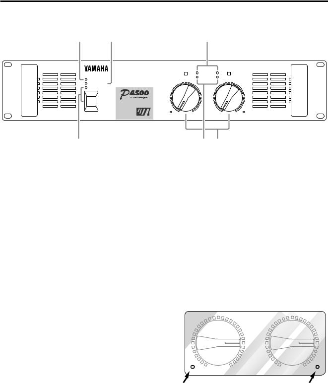
Controls and Functions
■ Front Panel
2 3
TEMP
PROTECTION
POWER
 ON
ON OFF
OFF
EEEngine
1
1POWER switch and indicator
This is the main POWER switch. Press to power ON the amplifier. Press again to power OFF. The POWER indicator lights up when the amplifier is powered ON.
2TEMP indicator
When the temperature of the heat sink exceeds 85 degrees Celsius, this indicator will light red.
3PROTECTION indicator
This red LED indicator lights up for approximately 3 seconds when the amplifier is powered ON, indicating that the soft-start protection system is working. No sound is output during soft-start up. If one of the protection systems is activated during normal use, this indicator lights up and no sound is output. The speaker system is actually disconnected from the amplifier outputs when this indicator lights up. The protection systems are activated when overheating occurs or a DC voltage is present at the amplifier outputs. If the problem is corrected, the protection systems deactivate automatically, this indicator goes out, and normal amplifier operation is resumed.
4
|
A |
CLIP |
|
B |
|
SIGNAL |
|
|
|
20 |
15 |
|
20 |
15 |
|
|
|
||
25 |
10 |
25 |
|
10 |
30 |
6 |
30 |
|
6 |
|
|
|
||
40 |
3 |
40 |
|
3 |
∞ |
0 |
–dB |
∞ |
0 |
5 6
4CLIP indicators
These red LED indicators light up when the respective channel’s output signal distortion exceeds 1% (i.e. clipping). Output signal clipping is usually due to excessive input signal levels.
5SIGNAL indicators
These green LED indicators light up when the respective
channel’s output signal exceeds 2 Vrms. This is equivalent to 1/2 watt into 8Ω, 1 W into 4Ω.
6Volume controls
These volume controls allow you to adjust the volume level in 31 steps in the range between –∞ dB and 0 dB.
To fix the volume setting by protecting the controls, install the included security cover over the controls and tighten the screws in the holes as shown below.
20 |
15 |
|
20 |
15 |
|
|
|
||
25 |
10 |
|
25 |
10 |
30 |
6 |
|
30 |
6 |
|
|
|
||
40 |
3 |
|
40 |
3 |
∞ |
0 |
–dB |
∞ |
0 |
2
 Loading...