


 Loading...
GEBRL
AV Amplifier
OWNER’S MANUAL
English
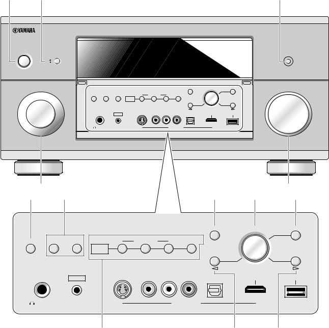
Front panel
A |
B |
|
|
|
|
|
|
|
|
|
|
|
|
C |
|
MAIN ZONE |
|
|
|
|
|
|
|
|
|
|
|
|
|
|
|
MASTER |
|
|
|
|
|
|
|
|
|
|
|
PURE DIRECT |
|
ON/OFF |
ON |
|
|
|
|
|
|
|
|
|
|
|
|
|
OFF |
|
|
|
|
|
|
|
|
|
|
|
|
|
|
INPUT |
|
|
|
|
|
|
|
|
|
STRAIGHT |
PROGRAM |
MENU |
VOLUME |
|
|
|
|
|
SPEAKERS |
|
|
|
|
ZONE |
|
|
|
|
|
|
|
AUDIO SELECT |
A |
B |
|
ZONE ON/OFF |
|
CONTROLS |
EFFECT |
|
|
|
|
|
|
|
|
|
MULTI |
|
|
|
|
|
|
|
|
|
|
|
|
|
|
ZONE |
|
|
|
|
|
REC OUT/ |
|
TONE CONTROL |
|
|
|
|
|
|
|
ZONE 2 |
ZONE 3 |
|
|
|
ZONE 2 |
|
|
|
|
|
|
|
|
|
|
|
|
|
|
|
|
||
|
|
|
|
|
|
|
|
ZONE 4 |
|
|
PUSH ENTER |
|
|
|
|
|
|
SILENT CINEMA |
YPAO |
S VIDEO |
VIDEO |
L |
AUDIO |
R |
OPTICAL |
HDMI IN |
USB |
|
|
|
|
|
|
|
OPTIMIZER |
|
|
|
|
|
|
|
|
|
|
|
|
PHONES |
MIC |
|
|
|
VIDEO AUX |
|
|
|
|
||
|
D |
|
|
|
|
|
|
|
|
|
|
|
|
E |
|
F |
G |
|
|
|
|
|
|
|
|
|
H |
I |
J |
|
|
|
|
|
|
|
|
|
|
|
|
STRAIGHT |
PROGRAM |
MENU |
|
|
SPEAKERS |
|
|
|
|
|
|
|
|
ZONE |
|
|
|
|
AUDIO SELECT |
A |
B |
|
|
ZONE ON/OFF |
|
|
|
CONTROLS |
EFFECT |
|
|
|
|
|
|
MULTI |
|
|
|
|
|
|
|
|
|
||
|
|
|
|
|
|
|
|
|
|
|
|
|
||
|
|
|
ZONE |
|
|
|
|
|
|
|
REC OUT/ |
|
TONE CONTROL |
|
|
|
|
|
|
ZONE 2 |
ZONE 3 |
ZONE 4 |
|
|
ZONE 2 |
|
|||
|
|
|
|
|
|
|
|
|
|
|||||
|
|
|
|
|
|
PUSH ENTER |
|
SILENT CINEMA |
YPAO |
S VIDEO |
VIDEO |
L AUDIO R |
OPTICAL |
HDMI IN |
USB |
|
OPTIMIZER |
|
|
|
|
|
|
PHONES |
MIC |
|
|
VIDEO AUX |
|
|
|
K L M
2 En
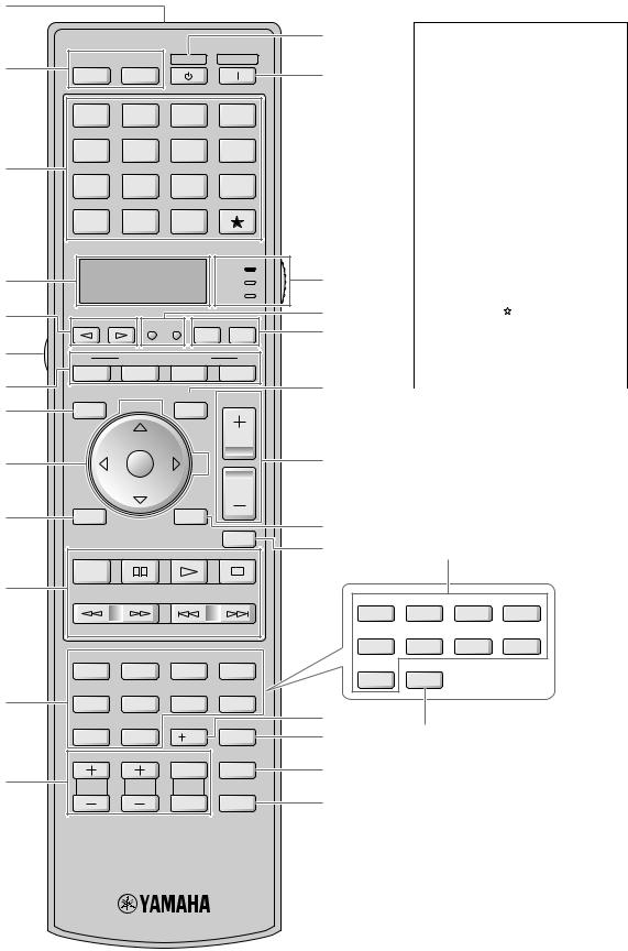
Remote control
1
2
3
4
5
6
7
8
9
0
A
B
C
POWER POWER STANDBY POWER
TV AV
MULTI |
V-AUX |
PHONO |
MD |
|
TAPE |
||||
|
|
|
||
BD |
DVD |
CD |
CD-R |
|
HD DVD |
||||
|
|
|
||
CBL |
DTV |
DVR |
VCR |
|
SAT |
||||
|
|
|
||
TUNER |
DOCK |
NET |
|
|
USB |
|
|||
|
|
|
||
|
|
|
AMP |
|
|
|
|
TV |
|
|
|
|
SOURCE |
|
SELECT |
SETUP |
ID MACRO |
||
|
|
MODE |
ZONE |
|
|
SYSTEM MEMORY |
|
||
1 |
2 |
3 |
4 |
|
LEVEL |
PRESET/CH |
SRCH MODE |
VOLUME |
|
TITLE |
MENU |
|
||
|
|
|||
BAND |
|
|
|
|
|
ENTER |
A-E |
|
|
RETURN |
|
DISPLAY |
|
|
MEMORY
MUTE
PC/MCX
REC
D |
Backlight mode |
|
|
The remote control is equipped with |
|
E |
the motion sensor and the remote |
|
control lights up the backlight |
||
|
||
|
corresponding to the motions or |
|
|
operation. If you do not want to |
|
|
lights up the backlight when this unit |
|
|
detects motions, change the backlight |
|
|
mode (see page 104). |
|
Simplified remote control |
|
|
This products is supplied with the |
|
|
simplified remote control. Refer to |
|
|
“Simplified remote control” on |
|
|
page 110. |
|
F |
Optional component control |
|
|
||
G |
area button ( ) |
|
H |
You can control the desired |
|
component without changing the |
||
|
||
|
input source of this unit (see |
|
I |
page 102). |
|
|
||
|
||
J |
|
|
K |
|
|
L |
Q |
NET RADIO |
USB |
|
|
CLASSICAL 1 |
CLASSICAL 2 |
LIVE/CLUB |
ENTERTAIN |
1 |
2 |
3 |
4 |
MOVIE |
STEREO |
ENHANCER |
SUR. DECODE |
5 |
6 |
7 |
8 |
THX |
STRAIGHT |
PURE DIRECT |
EXTD SUR. |
9 |
0 |
10 |
ENT |
PARTY |
SLEEP |
HDMI OUT |
AUDIO SEL |
|
|
MUTE |
AUDIO |
TV VOL |
TV CH |
TV |
3D DSP |
|
|
INPUT |
|
M N
O
P
CLASSICAL 1 |
CLASSICAL 2 |
LIVE/CLUB |
ENTERTAIN |
1 |
2 |
3 |
4 |
MOVIE |
STEREO |
ENHANCER |
SUR. DECODE |
5 |
6 |
7 |
8 |
THX |
STRAIGHT |
|
|
9 |
0 |
|
|
R
3 En
Limited Guarantee for European Economic Area (EEA) and Switzerland
Thank you for having chosen a Yamaha product. In the unlikely event that your Yamaha product needs guarantee service, please contact the dealer from whom it was purchased. If you experience any difficulty, please contact Yamaha representative office in your country. You can find full details on our website (http://www.yamaha-hifi.com/ or http://www.yamaha-uk.com/ for U.K. resident).
The product is guaranteed to be free from defects in workmanship or materials for a period of two years from the date of the original purchase. Yamaha undertakes, subject to the conditions listed below, to have the faulty product or any part(s) repaired, or replaced at Yamaha’s discretion, without any charge for parts or labour. Yamaha reserves the right to replace a product with that of a similar kind and/or value and condition, where a model has been discontinued or is considered uneconomic to repair.
Conditions
1.The original invoice or sales receipt (showing date of purchase, product code and dealer’s name) MUST accompany the defective product, along with a statement detailing the fault. In the absence of this clear proof of purchase, Yamaha reserves the right to refuse to provide free of charge service and the product may be returned at the customer’s expense.
2.The product MUST have been purchased from an AUTHORISED Yamaha dealer within the European Economic Area (EEA) or Switzerland.
3.The product must not have been the subject of any modifications or alterations, unless authorised in writing by Yamaha.
4.The following are excluded from this guarantee:
a.Periodic maintenance and repair or replacement of parts due to normal wear and tear.
b.Damage resulting from:
(1)Repairs performed by the customer himself or by an unauthorised third party.
(2)Inadequate packaging or mishandling, when the product is in transit from the customer. Please note that it is the customer’s responsibility to ensure the product is adequately packaged when returning the product for repair.
(3)Misuse, including but not limited to (a) failure to use the product for its normal purpose or in accordance with Yamaha’s instructions on the proper use, maintenance and storage, and (b) installation or use of the product in a manner inconsistent with the technical or safety standards in force in the country where it is used.
(4)Accidents, lightning, water, fire, improper ventilation, battery leakage or any cause beyond Yamaha’s control.
(5)Defects of the system into which this product is incorporated and/or incompatibility with third party products.
(6)Use of a product imported into the EEA and/or Switzerland, not by Yamaha, where that product does not conform to the technical or safety standards of the country of use and/or to the standard specification of a product sold by Yamaha in the EEA and/or Switzerland.
(7)Non AV (Audio Visual) related products.
(Products subject to “Yamaha AV Guarantee Statement” are defined in our website at http://www.yamaha-hifi.com/ or http://www.yamaha-uk.com/ for U.K. resident.)
5.Where the guarantee differs between the country of purchase and the country of use of the product, the guarantee of the country of use shall apply.
6.Yamaha may not be held responsible for any losses or damages, whether direct, consequential or otherwise, save for the repair or replacement of the product.
7.Please backup any custom settings or data, as Yamaha may not be held responsible for any alteration or loss to such settings or data.
8.This guarantee does not affect the consumer’s statutory rights under applicable national laws in force or the consumer’s rights against the dealer arising from their sales/purchase contract.
4 En
Caution: Read this before operating your unit.
1To assure the finest performance, please read this manual carefully. Keep it in a safe place for future reference.
2Install this sound system in a well ventilated, cool, dry, clean place – away from direct sunlight, heat sources, vibration, dust, moisture, and/or cold. Allow ventilation space of at least 30 cm on the top, 20 cm on the left and right, and 20 cm on the back of this unit.
3Locate this unit away from other electrical appliances, motors, or transformers to avoid humming sounds.
4Do not expose this unit to sudden temperature changes from cold to hot, and do not locate this unit in an environment with high humidity (i.e. a room with a humidifier) to prevent condensation inside this unit, which may cause an electrical shock, fire, damage to this unit, and/or personal injury.
5Avoid installing this unit where foreign objects may fall onto this unit and/or this unit may be exposed to liquid dripping or splashing. On the top of this unit, do not place:
–Other components, as they may cause damage and/or discoloration on the surface of this unit.
–Burning objects (i.e. candles), as they may cause fire, damage to this unit, and/or personal injury.
–Containers with liquid in them, as they may fall and liquid may cause electrical shock to the user and/or damage to this unit.
6Do not cover this unit with a newspaper, tablecloth, curtain, etc. in order not to obstruct heat radiation. If the temperature inside this unit rises, it may cause fire, damage to this unit, and/or personal injury.
7Do not plug in this unit to a wall outlet until all connections are complete.
8Do not operate this unit upside-down. It may overheat, possibly causing damage.
9Do not use force on switches, knobs and/or cords.
10When disconnecting the power cable from the wall outlet, grasp the plug; do not pull the cable.
11Do not clean this unit with chemical solvents; this might damage the finish. Use a clean, dry cloth.
12Only voltage specified on this unit must be used. Using this unit with a higher voltage than specified is dangerous and may cause fire, damage to this unit, and/or personal injury. Yamaha will not be held responsible for any damage resulting from use of this unit with a voltage other than specified.
13To prevent damage by lightning, keep the power cord and outdoor antennas disconnected from a wall outlet or the unit during a lightning storm.
14Do not attempt to modify or fix this unit. Contact qualified Yamaha service personnel when any service is needed. The cabinet should never be opened for any reasons.
15When not planning to use this unit for long periods of time (i.e. vacation), disconnect the AC power plug from the wall outlet.
16Install this unit near the AC outlet and where the AC power plug can be reached easily.
17Be sure to read the “Troubleshooting” section on common operating errors before concluding that this unit is faulty.
18Before moving this unit, press BMASTER ON/OFF to release it outward to the OFF position to turn off this unit, the main room, Zone 2, Zone 3, and Zone 4 and then disconnect the AC power plug from the AC wall outlet.
19VOLTAGE SELECTOR (Asia and General models only)
The VOLTAGE SELECTOR on the rear panel of this unit must be set for your local main voltage BEFORE plugging into the AC wall outlet. Voltages are as follows:
.................................................. 110/120/220/230–240 V AC, 50/60 Hz
20The batteries shall not be exposed to excessive heat such as sunshine, fire or like.
21Excessive sound pressure from earphones and headphones can cause hearing loss.
WARNING
TO REDUCE THE RISK OF FIRE OR ELECTRIC SHOCK, DO NOT EXPOSE THIS UNIT TO RAIN OR MOISTURE.
As long as this unit is connected to the AC wall outlet, it is not disconnected from the AC power source even if you turn off this unit by BMASTER ON/OFF. In this state, this unit is designed to consume a very small quantity of power.
■ For U.K. customers
If the socket outlets in the home are not suitable for the plug supplied with this appliance, it should be cut off and an appropriate 3 pin plug fitted. For details, refer to the instructions described below.
Note
The plug severed from the mains lead must be destroyed, as a plug with bared flexible cord is hazardous if engaged in a live socket outlet.
■ Special Instructions for U.K. Model
IMPORTANT
THE WIRES IN MAINS LEAD ARE COLOURED IN ACCORDANCE WITH THE FOLLOWING CODE:
Blue: NEUTRAL
Brown: LIVE
As the colours of the wires in the mains lead of this apparatus may not correspond with the coloured markings identifying the terminals in your plug, proceed as follows:
The wire which is coloured BLUE must be connected to the terminal which is marked with the letter N or coloured BLACK. The wire which is coloured BROWN must be connected to the terminal which is marked with the letter L or coloured RED.
Making sure that neither core is connected to the earth terminal of the three pin plug.
This symbol mark is according to the EU directive 2002/96/EC.
This symbol mark means that electrical and electronic equipment, at their end-of-life, should be disposed of separately from your household waste.
Please act according to your local rules and do not dispose of your old products with your normal household waste.
5En

Contents
Introduction |
|
Notices .......................................................................................... |
8 |
Features...................................................................................... |
10 |
Getting started........................................................................... |
11 |
Quick start guide....................................................................... |
13 |
Preparation |
|
Connections ............................................................................... |
20 |
Optimizing the speaker setting for your listening room |
|
(YPAO) .................................................................................. |
42 |
Before starting the automatic setup ............................................... |
42 |
Using the quick automatic setup.................................................... |
43 |
Using the basic automatic setup .................................................... |
44 |
Reviewing the result of the automatic setup ............................. |
45 |
Using advanced automatic setup ................................................... |
46 |
Basic Operation |
|
Playback..................................................................................... |
50 |
Basic procedure ............................................................................. |
50 |
Selecting the MULTI CH INPUT component............................... |
50 |
Selecting the HDMI OUT jack...................................................... |
51 |
Selecting the front speaker set ....................................................... |
51 |
Using the Zone B feature........................................................... |
51 |
Using your headphones ................................................................. |
51 |
Playing video sources in the background of an audio source........ |
51 |
Selecting audio input jacks |
|
(AUDIO SELECT).................................................................... |
52 |
Muting the audio output ................................................................ |
52 |
Using the sleep timer ..................................................................... |
52 |
Canceling the sleep timer .......................................................... |
52 |
Operating this unit |
|
by using the graphical user interface (GUI) menu .................... |
53 |
Items in GUI menu .................................................................... |
53 |
Basic controls in the GUI menu ................................................ |
53 |
Basic operation of the GUI menu |
|
by using the front panel controls........................................... |
53 |
Sound field programs ............................................................... |
54 |
Selecting sound field programs ..................................................... |
54 |
Sound field program descriptions.................................................. |
54 |
For audio music sources ............................................................ |
55 |
For various sources.................................................................... |
57 |
For visual sources of music....................................................... |
57 |
For parties.................................................................................. |
58 |
For game programs.................................................................... |
58 |
For movie sources ..................................................................... |
58 |
Stereo playback ......................................................................... |
59 |
For compression artifacts |
|
(Compressed Music Enhancer mode) ................................... |
59 |
Surround decoder mode............................................................. |
59 |
THX Surround mode ................................................................. |
59 |
Using sound field programs without surround speakers |
|
(Virtual CINEMA DSP)........................................................ |
60 |
Enjoying multi-channel sources and sound field programs with |
|
headphones (SILENT CINEMA).......................................... |
60 |
Using CINEMA DSP HD³ mode................................................... |
60 |
Enjoying unprocessed input sources.............................................. |
60 |
Deactivating the “STRAIGHT” mode ...................................... |
60 |
Using audio features ................................................................. |
61 |
Enjoying pure hi-fi sound .............................................................. |
61 |
Adjusting the tonal quality ............................................................ |
61 |
Adjusting the speaker level............................................................ |
61 |
Recording................................................................................... |
62 |
Internal Source Operation |
|
Using iPod™.............................................................................. |
64 |
Controlling iPod™........................................................................ |
64 |
Remote control operation ......................................................... |
64 |
Controlling iPod in the simple remote mode............................ |
64 |
Controlling iPod in the menu browse mode ............................. |
64 |
The functions of the play information display.......................... |
65 |
Using Network/USB features ................................................... |
66 |
Navigating the network and USB menus...................................... |
66 |
Remote control operation ......................................................... |
67 |
Using a PC server or Yamaha MCX-2000 ................................... |
68 |
Installing Windows Media Player 11 on your PC .................... |
68 |
Registering this unit on the Yamaha MCX-2000 ..................... |
68 |
Using the Internet Radio ............................................................... |
69 |
Storing your favorite Internet Radio stations |
|
with bookmarks .................................................................... |
69 |
Using a USB storage device or a USB portable audio player ...... |
69 |
Using shortcut buttons .................................................................. |
70 |
Assigning the items to the numeric button (1-8) ...................... |
70 |
Select an item by using numeric buttons (1-8) ......................... |
70 |
Advanced Operation |
|
Advanced sound configurations .............................................. |
72 |
Selecting decoders ........................................................................ |
72 |
Selecting decoders for 2-channel sources |
|
(surround decode mode)....................................................... |
72 |
Decoder descriptions ................................................................ |
72 |
Selecting decoders used with sound field programs................. |
72 |
Selecting decoders for multi-channel sources .......................... |
72 |
Playing back sources with the THX Surround modes .................. |
73 |
For 2-channel sources............................................................... |
73 |
For multi-channel sources ........................................................ |
73 |
Graphical user interface (GUI) menu..................................... |
74 |
GUI menu overview...................................................................... |
76 |
Stereo/Surround (Stereo/Surround menu) .................................... |
77 |
Input Select ................................................................................... |
81 |
Manual Setup (Basic).................................................................... |
83 |
Manual Setup (Volume)................................................................ |
86 |
Manual Setup (Sound) .................................................................. |
86 |
Manual Setup (Video)................................................................... |
89 |
Manual Setup (Multi Zone) .......................................................... |
91 |
Manual Setup (Network) .............................................................. |
92 |
Manual Setup (Option) ................................................................. |
93 |
Signal Info. (Input signal information) ......................................... |
95 |
Language....................................................................................... |
95 |
Saving and recalling the system settings |
|
(System Memory).................................................................. |
96 |
Saving the current system settings................................................ |
96 |
Saving by the SYSTEM MEMORY buttons............................ |
96 |
Saving by the GUI menu operation .......................................... |
96 |
Renaming the stored settings.................................................... |
97 |
Saved parameters for the main zone......................................... |
98 |
Saved parameters for Zone 2, Zone 3, or Zone 4 ..................... |
98 |
Loading the stored system settings ............................................... |
98 |
Loading by the SYSTEM MEMORY buttons ......................... |
98 |
Loading by the GUI menu operation........................................ |
98 |
Using examples............................................................................. |
99 |
Example 1: Switching the settings |
|
of this unit according to the using situations........................ |
99 |
Example 2: Switching the setting of this unit according |
|
to the environment of the listening room ........................... |
100 |
Controlling this unit by using the Web browser |
|
(Web Control Center)......................................................... |
101 |
6 En

Remote control features ......................................................... |
102 |
Controlling this unit, a TV, or other components........................ |
102 |
Controlling this unit ................................................................ |
102 |
Controlling a TV ..................................................................... |
102 |
Controlling other components................................................. |
103 |
Selecting a component to be controlled .................................. |
103 |
Controlling optional components (Option mode) ................... |
103 |
Customizing the remote control .................................................. |
104 |
Setting the backlight mode of the remote control (LIGHT)........ |
104 |
Setting remote control codes (P-SET)......................................... |
104 |
Programming codes from other remote controls (LEARN)........ |
105 |
Changing source names in the display window (RNAME) ........ |
106 |
Macro programming features ...................................................... |
107 |
Recalling programmed macro-operations ............................... |
107 |
Default macro functions.......................................................... |
108 |
Programming macro operations (MACRO)............................ |
108 |
Clearing configurations ............................................................... |
109 |
Clearing function sets (CLEAR)............................................. |
109 |
Clearing a learned function (ERASE)..................................... |
109 |
Simplified remote control............................................................ |
110 |
Setting the controlling zone of the simplified remote control .......... |
110 |
Replacing the battery in the simplified remote control........... |
110 |
Using multi-zone configuration ............................................. |
111 |
Step1: Planning the multi-zone system ....................................... |
111 |
Step2: Connecting the speakers, external amplifiers, |
|
and/or other components ......................................................... |
112 |
Using the internal amplifier of this unit .................................. |
112 |
Using external amplifiers ........................................................ |
113 |
Using the ZONE DIGITAL OUT (COAXIAL) jack.............. |
113 |
Connecting Zone video monitor.............................................. |
114 |
Video signal up-conversion |
|
to the zone component video signals .................................. |
114 |
Using REMOTE IN/OUT and TRIGGER OUT jacks |
|
for Zone 2, Zone 3, and Zone 4 .......................................... |
115 |
Step3: Setting the zone parameter ............................................... |
116 |
Assigning the zone speakers ................................................... |
116 |
Controlling Zone 2, Zone 3, or Zone 4........................................ |
116 |
Basic operation........................................................................ |
116 |
Selecting the input source Zone 2, Zone 3, or Zone 4 ............ |
117 |
Adjusting the volume level of Zone 2, Zone 3, or Zone 4........... |
117 |
Setting the sleep timer for Zone 2, Zone 3, or Zone 4 ............ |
117 |
Adjusting the tonal quality of Zone 2, Zone 3, or Zone 4 ........... |
118 |
Using the Zone OSD ............................................................... |
118 |
Using the party mode .................................................................. |
118 |
Advanced setup....................................................................... |
119 |
Using the advanced setup menu .................................................. |
119 |
Additional Information |
|
Troubleshooting...................................................................... |
122 |
Glossary ................................................................................... |
128 |
Parametric equalizer information......................................... |
135 |
Block diagrams ....................................................................... |
136 |
Specifications........................................................................... |
138 |
Index ........................................................................................ |
140 |
List of remote control codes................................................... |
144 |
Contents
“BMASTER ON/OFF” or “3DVD” (example) indicates the name of the parts on the front panel or the remote control. Refer to the cover pages at the top of this manual for the information about each position of the parts.
Introduction |
|
|
|
|
|
Preparation |
|
|
|
|
|
Operation Basic |
|
|
|
|
|
Operation |
Source Internal |
|
|
|
|
Operation |
Advanced |
|
|
|
|
Information |
Additional |
|
|
7 En

Notices
About this manual
•y indicates a tip for your operation.
•Some operations can be performed by using either the buttons on the front panel or the ones on the remote control. In case the button names differ between the front panel and the remote control, the button name on the remote control is given in parentheses.
•This manual is printed prior to production. Design and specifications are subject to change in part as a result of improvements, etc. In case of differences between the manual and product, the product has priority.
•This unit is equipped with GUI language switching capability. In this manual, the illustrations of the GUI are examples when you set the GUI language to English.
•“AMAIN ZONE ON/OFF” or “3DVD” (example) indicates the name of the parts on the front panel or the remote control. Refer to the cover pages at the top of this manual for the information about each position of the parts.
•The symbol “ ” with page number(s) indicates the corresponding reference page(s).
Manufactured under license from Dolby Laboratories.
“Dolby”, “Pro Logic”, and the double-D symbol are trademarks of Dolby Laboratories.
Manufactured under license under U.S. Patent No’s: 5,451,942;5,956,674;5,974,380;5,978,762;6,226,616;6,487,535 & other U.S. and worldwide patents issued & pending. DTS is a registered trademark and the DTS logos, Symbol, DTS-HD and DTS-HD Master Audio are trademark of DTS, Inc. © 1996-2007 DTS, Inc. All Rights Reserved.
THX, the THX logo and Ultra2 Plus are trademarks of THX Ltd. which may be registered in some jurisdictions. All rights reserved. All other trademarks are the property of their respective owners.
iPodTM
“iPod” is a trademark of Apple Inc., registered in the U.S. and other countries.
MPEG Layer-3 audio coding technology licensed from Fraunhofer IIS and Thomson.
This amplifier supports network connections.
“HDMI”, the “HDMI” logo, and “High-Definition Multimedia Interface” are trademarks or registered trademarks of HDMI Licensing LLC.
“SILENT CINEMA” is a trademark of Yamaha Corporation.
Windows XP, Windows Vista, Windows Internet Explorer, Windows Media Audio, Windows Media Connect, and Windows Media Player are either registered trademarks or trademarks of Microsoft corporation in the United States and/or other countries.
The PlaysForSure logo, Windows Media and the Windows logo are trademarks or registered trademarks of Microsoft Corporation in the United States and/or other countries.
Content providers are using the digital rights management technology for Windows Media contained in this device (WM-DRM) to protect the integrity of their content (Secure Content) so that their intellectual property, including copyright, in such content is not misappropriated.
This device uses WM-DRM software to play Secure Content (WM-DRM Software).
If the security of the WM-DRM Software in this device has been compromised, owners of Secure Content (Secure Content Owners) may request that Microsoft revoke the WM-DRM Software’s right to acquire new licenses to copy, display and/or play Secure Content. Revocation does not alter the WM-DRM Software’s ability to play unprotected content. A list of revoked WM-DRM Software is sent to your device whenever you download a license for Secure Content from the Internet or from a PC. Microsoft may, in conjunction with such license, also download revocation list onto your device on behalf of Secure Content Owners.
8 En

Introduction
Introduction |
|
Features ................................................................................................ |
10 |
Getting started ..................................................................................... |
11 |
Supplied accessories ................................................................................................................ |
11 |
Using the remote control ......................................................................................................... |
12 |
Opening and closing the front panel door ............................................................................... |
12 |
VOLTAGE SELECTOR (Asia and General models only) ...................................................... |
12 |
Quick start guide .................................................................................. |
13 |
Preparation: Check the items ................................................................................................... |
13 |
Step 1: Set up your speakers .................................................................................................... |
14 |
Step 2: Connect your Blu-ray Disc/HD DVD player and other components .......................... |
16 |
Step 3: Turn on the power and start playback ......................................................................... |
17 |
What do you want to do with this unit? ................................................................................... |
18 |

Features
Built-in 11-channel power amplifier
Minimum RMS output power
(20 Hz to 20 kHz, 0.04% THD, 8 Ω) Front: 140 W + 140 W
Center: 140 W
Surround: 140 W + 140 W Surround back: 140 W + 140 W Front presence: 50 W + 50 W Rear presence: 50 W + 50 W
Sound field programs P. 54
Proprietary Yamaha technology for the creation of sound fieldsTHX Ultra2 Plus surround modes P. 73
CINEMA DSP HD³ mode for creating intensive and accurate stereoscopic sound field P. 60
Compressed Music Enhancer mode to improve the sound quality of compression artifacts (such as the MP3 format) to that of a high-quality
multi-channel source playback P. 59Virtual CINEMA DSP P. 60
SILENT CINEMA P. 60
Digital audio decoders
Dolby TrueHD, Dolby Digital Plus decoder
DTS-HD Master Audio, DTS-HD High Resolution Audio decoder
Dolby Digital/Dolby Digital EX decoder
DTS/DTS-ES Matrix 6.1, Discrete 6.1, DTS 96/24 decoder
Dolby Pro Logic/Dolby Pro Logic II/Dolby Pro Logic IIx decoder
DTS NEO:6 decoder
HDMI™ (High-Definition Multimedia Interface) P. 28
HDMI interface for standard, enhanced or high-definition video as well as multi-channel digital audio based on HDMI version 1.3a
Automatic audio and video synchronization (lip sync) information capability
Deep Color (30/36 bit) and xvYCC color video signal transmission capability
High refresh rate and high resolution video signals capability
High definition digital audio format signals capability
Analog video to HDMI digital video up-conversion (composite video ↔ S-video ↔ component video → HDMI digital video) capability for
monitor out
Analog and HDMI video signal up-scaling P. 89 iPod controlling capability P. 64
DOCK terminal to connect a Yamaha iPod universal dock (such as the YDS-10, sold separately), which supports iPod (Click and Wheel), iPod nano, and iPod mini
Network features P. 66
NETWORK port to connect a PC and Yamaha MCX-2000 or access the Internet Radio via LAN
DHCP automatic or manual network configuration
USB features P. 69
USB ports to connect a USB storage device, USB Hard disc drive, or a USB portable audio player
Web control feature
Web control capability of this unit by using a Web browserP. 101
Automatic speaker setup features
Advanced YPAO (Yamaha Parametric Room Acoustic Optimizer) for automatic speaker setup P. 42
Specialized parametric equalizer for the standing wave reduction
P. 44
Multiple point measurement feature for multiple listening positions
P. 46
Speaker angle measurement feature for the optimized CINEMA DSP
effect P. 60
Other features
192-kHz/24-bit D/A converter
GUI (graphical user interface) menus that allow you to optimize this unit
to suit your individual audio/video system P. 74
GUI display menu language switching capability (English, Japanese, French, German, Spanish and Russian) P. 95
6 or 8-channel additional input jacks for discrete multi-channel inputP. 35
Multiple subwoofers connection capability P. 25
Analog video interlace/progressive conversion from 480i (NTSC)/576i (PAL) to 480p/576p
S-video signal input/output capability P. 29
Component video input/output capability includes (4 COMPONENT VIDEO INs and 2 MONITOR OUTs) P. 28
Optical and coaxial digital audio signal jacks P. |
28 |
|
Pure Direct mode for pure hi-fi sound for all sources |
P. 61 |
|
Adaptive dynamic range controlling capability |
P. 86 |
|
Adaptive DSP effect level controlling capability |
P. 86 |
|
Remote control with preset remote control codes, learning, macro and buttons and display backlight capability P. 102
Simplified remote control P. 110
Advanced amplifier assign capability P. 119Flexible assignable trigger out jack P. 94
Zone switching capability between the main zone and Zone 2/Zone 3/ Zone 4 using ZONE CONTROLS P. 91
Zone 2 video output (composite and component) and displaying OSD (on-screen display) capability P. 114
System Memory capability for saving and recalling multiple system parameter settings P. 96
Sleep timer P. 52
10 En
Getting started
Supplied accessories
Check that you received all of the following parts.
Remote control |
Simplified remote control |
||||||
POWER |
POWER |
STANDBY |
POWER |
STANDBY |
|
|
POWER |
TV |
AV |
|
|
|
|
|
|
|
|
|
|
|
|
||
MULTI |
V-AUX |
PHONO |
MD |
|
|
|
|
TAPE |
|
|
|
|
|||
|
|
|
|
|
|
|
|
BD |
DVD |
CD |
CD-R |
|
SYSTEM MEMORY |
||
HD DVD |
|
||||||
|
|
|
|
||||
CBL |
DTV |
DVR |
VCR |
1 |
2 |
3 |
4 |
SAT |
|
|
|
|
|||
TUNER |
DOCK |
NET |
|
|
|
|
|
USB |
|
|
|
|
|
||
|
|
|
|
|
|
|
|
|
|
|
|
|
|
INPUT |
|
|
|
|
AMP |
|
|
|
|
|
|
|
TV |
INT SOURCE |
|
VOLUME |
|
|
|
|
SOURCE |
|
|||
|
|
|
|
PRESET |
|
|
|
SELECT |
SETUP |
ID MACRO |
|
|
|
|
|
|
|
MODE |
ZONE |
|
|
|
|
|
SYSTEM MEMORY |
|
|
|
|
|
|
1 |
2 |
3 |
4 |
|
|
|
|
LEVEL |
PRESET/CH |
SRCH MODE |
VOLUME |
|
|
|
|
TITLE |
MENU |
|
|
|
|
|
|
BAND |
|
|
|
|
|
|
MUTE |
|
|
|
|
|
|
|
|
|
ENTER |
A-E |
|
|
|
|
|
RETURN |
|
DISPLAY |
|
|
|
|
|
MEMORY |
|
|
MUTE |
|
|
|
|
|
|
|
|
|
|
|
|
PC/MCX |
|
|
|
|
|
|
|
REC |
|
|
|
|
|
|
|
NET RADIO |
USB |
|
|
|
|
|
|
CLASSICAL 1 |
CLASSICAL 2 |
LIVE/CLUB |
ENTERTAIN |
Optimizer microphone |
|||
MOVIE |
STEREO |
ENHANCER SUR. DECODE |
|||||
1 |
2 |
3 |
4 |
|
|
|
|
5 |
6 |
7 |
8 |
|
|
|
|
THX |
STRAIGHT |
PURE DIRECT |
EXTD SUR. |
|
|
|
|
9 |
0 |
10 |
ENT |
|
|
|
|
PARTY |
SLEEP |
HDMI OUT |
AUDIO SEL |
|
|
|
|
|
|
MUTE |
AUDIO |
|
|
|
|
TV VOL |
TV CH |
TV |
3D DSP |
|
|
|
|
|
|
INPUT |
|
|
|
|
|
Batteries (4) |
Microphone base |
(AAA, LR03) |
|
|
FRONT |
|
DIRECTION |
Power cable (Two for Asia model)
Introduction
Note
The form of the supplied accessories varies depending on the models.
■ Installing batteries in the remote control
3 1
1
2
1Take off the battery compartment cover.
2Insert the four supplied batteries (AAA, LR03) according to the polarity markings
(+ and –) on the inside of the battery compartment.
3Snap the battery compartment cover back into place.
Notes
•Change all of the batteries if you notice the operation range of the remote control decreases.
•Do not use old batteries together with new ones.
•Do not use different types of batteries (such as alkaline and manganese batteries) together. Read the packaging carefully as these different types of batteries may have the same shape and color.
•We strongly recommend that you use alkaline batteries.
•If the batteries have leaked, dispose of them immediately. Avoid touching the leaked material or letting it come into contact with clothing, etc. Clean the battery compartment thoroughly before installing new batteries.
•Do not throw away batteries with general house waste; dispose of them correctly in accordance with your local regulations.
•If the remote control is without batteries for more than 2 minutes, or if exhausted batteries remain in the remote control, the contents of the memory may be cleared. When the memory is cleared, insert new batteries, set up the remote control code and program any acquired functions that may have been cleared.
11 En
Getting started
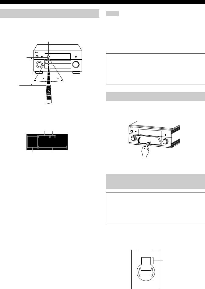
Using the remote control
The remote control transmits a directional infrared ray.
Be sure to aim the remote control directly at the remote control sensor on this unit during operation.
Remote control sensor
Notes
•Do not spill water or other liquids on the remote control.
•Do not drop the remote control.
•Do not leave or store the remote control in the following types of conditions:
–places of high humidity, such as near a bath
–places of high temperatures, such as near a heater or stove
–places of extremely low temperatures
–dusty places
Approximately |
30 |
30 |
6 m (20 ft) |
6LIGHT
Lights up the remote control buttons and the display window (4).
Display window (4)
[1] [2]
MAIN ID 1 ID 2
ZONE 2
ZONE 3
ZONE 4
[3][4]
[1]ID1/ID2 indicator
Indicates the currently selected remote control ID (see page 119).
[2] Transmit indicator
Appears while the remote control is sending infrared signals.
[3] Zone indicators
Indicates the currently controlling zone (see page 116).
[4] Information display
Shows the name of the selected input source that you can control.
Infrared window (1)
Outputs infrared control signals. Aim this window at the component you want to operate.
Operation mode selector (F)
The function of some buttons depends on the operation mode selector position.
AMP
Operates the amplifier function of this unit.
SOURCE
Operates the component selected with an input selector button (see page 103).
TV
Operates the TV (see page 102).
Backlight mode
The remote control is equipped with the motion sensor and the remote control lights up the backlight corresponding to the motions or operation. If you do not want to lights up the backlight when this unit detects motions, change the backlight mode (see page 104).
Opening and closing the front panel door
When you want to use the controls behind the front panel door, open the door by gently pressing on the lower part of the panel. Keep the door closed when not using these controls.
To open, press gently on the lower part of the panel.
VOLTAGE SELECTOR
(Asia and General models only)
Caution
The VOLTAGE SELECTOR on the rear panel of this unit must be set for your local voltage BEFORE plugging the power cable into the AC wall outlet. Improper setting of the VOLTAGE SELECTOR may cause damage to this unit and create a potential fire hazard.
Rotate the VOLTAGE SELECTOR clockwise or counterclockwise to the correct position using a straight slot screwdriver.
Voltages are as follows:
...................... AC 110/120/220/230–240 V, 50/60 Hz
VOLTAGE |
|
SELECTOR |
|
230- |
Voltage indication |
240V |
|
12 En
Quick start guide
The following steps describe the easiest way to enjoy Blu-ray Disc/HD DVD movie playback in your home theater. See pages 21 to 24 for details of the speaker placement.
Right front |
Front right |
presence |
|
Right
subwoofer
Left front
presence
Surround
right
Center
Right rear presence
Front left
Left
subwoofer Surround back right
|
Surround left |
Surround |
|
Blu-ray Disc/HD DVD player |
back left |
||
|
Left rear presence
Step 1: Set up your speakers
P. 14
Step 2: Connect your Blu-ray Disc/ HD DVD player and other components
P. 16
Step 3: Turn on the power and start playback
P. 17
Enjoy Blu-ray Disc/HD DVD
playback!
Preparation: Check the items
In these steps, you need the following supplied accessory.
Power cable
The following items are not included in the package of this unit.
Speakers |
|
Front speaker ................................................... |
x 2 |
Center speaker ................................................ |
x 1 |
Surround speaker ............................................ |
x 4 |
Front presence speaker .................................. |
x 2 |
Rear presence speaker ................................... |
x 2 |
Select magnetically shielded speakers. The minimum required speakers are two front speakers. The priority of the requirement of other speakers is as follows:
1.Two surround speakers
2.One center speaker
3.One (or two) surround back speaker(s)
4.Two front presence speakers
5.Two rear presence speakers
Active subwoofers ............................................... |
x 2 |
Select active subwoofers equipped with an RCA input jack.
Speaker cable ..................................................... |
x 11 |
Subwoofer cables ................................................ |
x 2 |
Select monaural RCA cables. |
|
HDMI cables ......................................................... |
x 2 |
Select HDMI cables shorter than 5 meters (16 feet) with the |
|
HDMI logo printed on it. |
|
Blu-ray Disc/HD DVD player ................................ |
x 1 |
Select Blu-ray Disc/HD DVD player equipped with an |
|
HDMI output jack. |
|
Video monitor........................................................ |
x 1 |
Select a TV monitor, video monitor or projector equipped with an HDMI input jack.
Introduction
13 En

Quick start guide
Step 1: Set up your speakers
Place your speakers in the room and connect them to this unit.
1 |
2 |
3 |
4 |
1 |
Make sure that this unit and the subwoofers are unplugged from the AC wall |
||
|
|
|
|
|
outlets. |
|
|
|
|
|
|
2 |
Twist the exposed wires of the speaker cables together to prevent short circuits. |
||
|
|
|
|
3 |
Do not let the bare speaker wires touch each other. |
|
|
|
|
|
|
4 |
Do not let the bare speaker wires touch any metal part of this unit. |
||
|
Right front |
|
Right rear |
|
|
|
|
presence speaker |
|
presence speaker |
|
Loosen |
Insert |
Tighten |
|
Surround right |
Surround back |
Front right |
Center speaker |
speaker |
right speaker |
speaker |
|
For other speaker configurations
If you want to connect less than 11 speakers and 2 subwoofers, connect the speakers as follows.
Front left |
Front |
Center |
Surround Surround |
Surround Surround |
Front |
Front |
Rear |
Rear |
||
presence |
presence |
presence |
presence |
|||||||
right |
left |
right |
back left back right |
|||||||
|
|
|
|
|
|
left |
right |
left |
right |
|
Subwoofer Subwoofer
left right
11.2/11.1
9.2/9.1
7.2/7.1
6.2/6.1
5.2/5.1
3.2/3.1
2.2/2.1
14 En

0 |
0 |
Left subwoofer |
Right subwoofer |
Subwoofer |
|
cable |
|
Subwoofer cable |
|
Quick start guide
|
|
|
|
Left rear |
|
|
|
|
Left front |
||||||||||||||||||||||||
presence speaker |
presence speaker |
||||||||||||||||||||||||||||||||
|
|
|
|
|
|
|
|
|
|
|
|
|
|
|
|
|
|
|
|
|
|
|
|
|
|
|
|
|
|
|
|
|
|
|
|
|
|
|
|
|
|
|
|
|
|
|
|
|
|
|
|
|
|
|
|
|
|
|
|
|
|
|
|
|
|
|
|
|
|
|
|
|
|
|
|
|
|
|
|
|
|
|
|
|
|
|
|
|
|
|
|
|
|
|
|
|
|
|
|
|
|
Introduction
Surround left |
speaker |
|
|
|
|
|
|
|
|
|
|
|
|
|
|
|
|
|
|
|
|
|
|
|
|
|
|
|
|
|
|
|
|
|
|
|
|
|
|
|
|
|
|
|
|
|
|
|
|
|
|
|
|
|
|
|
|
|
|
|
|
|
|
|
|
|
|
|
|
|
|
|
|
|
|
|
|
|
|
|
|
|
|
|
|
|
|
|
|
|
|
|
|
Surround back |
Front left speaker |
|||||||||||||||||||||
|
|
left speaker |
|
|
|
|
|
|
|
|
|
|
|
|
||||||||
Be sure to connect the left channel (L), right channel (R), “+” (red line) and “–” (white line) properly.
Note
Check the impedance of the speaker you are connecting. If the impedance of your speaker is 6-ohm, change the setting of “SPEAKER IMP.” in “Advanced setup” (see page 119).
15 En
Quick start guide
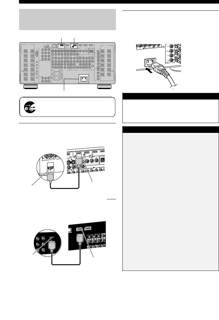
Step 2: Connect your Blu-ray Disc/HD DVD player and other components
HDMI OUT 1 BD/HD DVD HDMI IN 1
|
HDMI |
OUT 1 |
IN1 |
BD/HD DVD |
3Connect the supplied power cable to AC IN on this unit and then plug the power cable and other components into the AC wall outlet.
y
This unit is equipped with AC OUTLET(S) that provide(s) power to other components. See page 38 for details.
AC IN
AC IN
Make sure that this unit and the Blu-ray Disc/HD DVD player are unplugged from the AC wall outlets.
1Connect an HDMI cable to the HDMI output jack on your Blu-ray Disc/HD DVD player and the BD/HD DVD HDMI IN 1 jack of this unit.
AV amplifier
Blu-ray Disc/HD DVD player
BD/HD DVD
HDMI IN 1 jack
HDMI output jack
HDMI cable
2Connect an HDMI cable to the HDMI OUT 1 jack on this unit and the HDMI input jack on your video monitor.
AV amplifier
Video monitor
HDMI input |
|
jack |
HDMI OUT 1 jack |
|
|
|
HDMI cable |
To the AC wall outlet
General connection information
• General information on jacks and cable plugs |
P. 28 |
|
• |
General information on HDMI |
P. 28 |
• |
Speaker impedance setting |
P. 39 |
|
|
|
For further connections
• Using other kinds of speaker combinations |
P. 21 |
•Connecting a video monitor via various ways of connection
P. 30
•Connecting a Blu-ray Disc/HD DVD player via various ways
of connection |
P. 31 |
•Connecting a DVD player via various ways of connection
P. 32
•Connecting a DVD recorder or a digital video recorder
P. 33
• Connecting a set-top box |
P. 32 |
•Connecting a CD player, an MD recorder, or a turntable
P. 34
• Connecting an external amplifier |
P. 35 |
• Connecting a DVD player via multi-channel analog audio |
|
connection |
P. 35 |
• Connecting a Yamaha iPod universal dock |
P. 36 |
• Using the REMOTE IN/OUT jacks |
P. 36 |
• Using the TRIGGER OUT jacks |
P. 36 |
• Using the VIDEO AUX jacks on the front panel |
P. 38 |
• Connecting this unit to your network |
P. 37 |
• Connecting a USB device |
P. 37 |
16 En
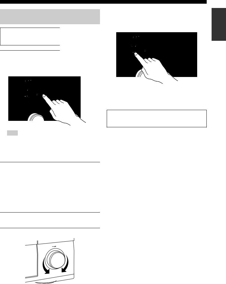
Step 3: Turn on the power and start playback
Check the type of the connected speakers.
If the speakers are 6-ohm speakers, set “SPEAKER IMP.” to “6Ω MIN” before using this unit (see page 119).
1Turn on the video monitor connected to this unit.
2Press BMASTER ON/OFF inward to the ON position on the front panel.
Note
After this unit is turned on, it takes approximately 20 seconds until this unit produces sounds, and while “Please wait” appears in the front panel display, this unit does not accepts the front panel operations and stores the remote control operations. This unit performs the stored remote control operations after “Please wait” disappears.
3Rotate the DINPUT selector to set the input source to “BD/HD DVD”.
y
The recommended sound field program is set for each input source (BD/HD DVD, etc.). You can also use various sound field programs and other sound modes for playback. Refer to the following pages for details:
–see pages 60 and 72 to use various sound field programs
–see page 60 to turn on or off the sound effect
–see page 61 to use the pure direct mode for high fidelity sound
4Start playback of the desired Blu-ray Disc/HD DVD source on your player.
5Rotate EVOLUME to adjust the volume.
Quick start guide
■ After using this unit...
Press AMAIN ZONE ON/OFF to set this unit to the standby mode.
This unit is set to the standby mode and consumes a small amount of power in order to receive infrared signals from the remote control. To turn on this unit from the standby mode, press AMAIN ZONE ON/OFF on the front panel (or EPOWER on the remote control). See page 39 for details.
Automatic setup feature
To optimize the speaker settings for your listening room, use the automatic setup feature. See pages 43 to 48 for details.
■ Are you enjoying playback?
If there are some troubles with playback, check the settings as follows.
No sound is output.
Are the speakers connected correctly? Â Check the speaker connection.
Are Your Blu-ray Disc/HD DVD player connected correctly?
ÂCheck the connection of the Blu-ray Disc/HD DVD player. Are the front speakers selected correctly?
ÂPress GSPEAKERS A or GSPEAKERS B.
Is volume setting correct? Â Adjust the volume level.
Does the Blu-ray Disc/HD DVD player play back correctly? Â Check the setting of the Blu-ray Disc/HD DVD player.
No picture.
Is the video monitor connected correctly?
 Check the connection of the video monitor.
If the video monitor is connected to the HDMI OUT 1 jack of this unit, is the “HDMI OUT SEL” setting correct?
ÂSet the operation mode selector to FAMP and then press CHDMI OUT repeatedly to set “HDMI OUT SEL” to
“OUT 1”.
Is Blu-ray Disc/HD DVD player connected correctly? Â Check the connection of the video monitor.
Is the input source setting of the video monitor correct?
 Check the setting of the input source of the video monitor.
Any other troubles?
Refer to “Troubleshooting” on pages 122 to 127 for other troubles.
Introduction
17 En

Quick start guide
What do you want to do with this unit?
Using various input sources
• Basic operations of this unit |
P. 50 |
|
• Using your iPod with this unit |
P. 64 |
|
• Enjoying the contents stored on your PC |
P. 66 |
|
• |
Enjoying Internet radio programs and Podcasts |
P. 69 |
• |
Using USB devices with this unit |
P. 69 |
|
|
|
Using various sound features
• Using various sound field programs |
P. 54 |
|
• Using the Pure Direct mode for high fidelity sound |
P. 61 |
|
• |
Adjusting the tonal quality of the speakers |
P. 61 |
• |
Customizing the sound field programs |
P. 72 |
|
|
|
Additional features
• Setting the remote control |
P. 102 |
• Displaying the current input source signal information in the
GUI |
P. 95 |
• Saving and recalling the system settings of this unit |
|
(System Memory) |
P. 96 |
• Controlling this unit using a Web browser |
P. 101 |
• Using headphones |
P. 51 |
• Using this unit in multiple rooms simultaneously |
|
(multi-zone configuration) |
P. 111 |
• Automatically turning off this unit |
P. 52 |
Manually adjusting various parameters of this unit
• Setting the language of the GUI menu |
P. 95 |
• Assigning the input/output jacks on this unit
P. 81
• Setting the parameters for each input source
P. 81
• Setting the parameters related to the volume level
P. 86
• Adjusting the tonal quality of each channel manually by using
the parametric equalizer |
P. 87 |
• Adjusting the audio and video synchronization |
P. 88 |
• Muting the selected speaker channel |
P. 89 |
• Setting the parameters related to the video signals |
|
|
P. 89 |
• Setting the basic speaker configuration |
P. 83 |
• Setting the network parameters |
P. 92 |
• Setting the parameters of the multi-zone feature |
P. 92 |
• Protecting the various settings |
P. 94 |
Adjusting the advanced parameters
•Setting the speaker impedance of the connected speakers
P. 119
• Setting the language of the GUI menu |
P. 120 |
•Setting the video format of the connected video monitor
P. 120
•Setting the parameters of this unit to default values
P. 127
18 En

Preparation
Preparation
Connections ......................................................................................... |
20 |
Rear panel .......................................................................................................................... |
20 |
Placing speakers ................................................................................................................. |
21 |
Connecting speakers .......................................................................................................... |
23 |
Using subwoofers .............................................................................................................. |
25 |
Using presence speakers .................................................................................................... |
26 |
Connecting the speaker cable ............................................................................................ |
27 |
Information on jacks and cable plugs ................................................................................ |
28 |
Information on HDMI™ .................................................................................................... |
28 |
Audio and video signal flow .............................................................................................. |
29 |
Connecting a TV monitor or projector .............................................................................. |
30 |
Connecting other components ........................................................................................... |
31 |
Connecting the network ..................................................................................................... |
37 |
Connecting the USB storage devices to the USB ports ..................................................... |
37 |
Connecting the power cable ............................................................................................... |
38 |
Using the VIDEO AUX jacks on the front panel .............................................................. |
38 |
Setting the speaker impedance and language .................................................................... |
39 |
Turning this unit on and off ............................................................................................... |
39 |
Front panel display ............................................................................................................ |
40 |
Optimizing the speaker setting for your listening room (YPAO)........ |
42 |
Before starting the automatic setup ................................................................................... |
42 |
Using the quick automatic setup ........................................................................................ |
43 |
Using the basic automatic setup ........................................................................................ |
44 |
Using advanced automatic setup ....................................................................................... |
46 |
Connections
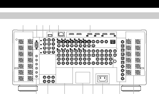
Rear panel
1 |
2 |
3 |
4 |
5 |
6 |
SPEAKERS |
USB |
NETWORK |
|
HDMI |
|
|
|
|
|
|
|
|
|
|
SPEAKERS |
|
|
OUT 1 |
OUT 2 |
IN1 |
IN2 |
IN3 |
IN4 |
|
|
BD/HD DVD |
DVD |
CBL/SAT |
DVR |
|
RS-232C COMPONENT VIDEO |
|
S VIDEO |
VIDEO IN |
|
|
|
VIDEO OUT |
|
|
ZONE OUT |
|
DOCK |
DIGITAL OUT |
|
|
|||||
+ |
BD/ |
Y |
PB |
PR |
|
|
|
|
|
MONITOR |
VIDEO |
COMPONENT VIDEO |
|
+ |
|||||||
R |
HD DVD |
|
|
|
1 DVD |
2 DTV |
3 CBL/SAT |
4 DVR |
5 VCR |
4 DVR |
5 VCR |
OUT |
|
Y |
PB |
PR |
|
|
|
|
L |
REAR |
A |
|
|
|
|
|
|
|
|
|
|
|
|
|
|
|
|
|
|
|
REAR |
PRESENCE |
|
|
|
|
|
|
|
|
|
|
|
|
|
|
|
|
|
|
ZONE |
|
PRESENCE |
/ZONE |
|
|
|
|
|
|
|
|
|
|
|
|
|
|
|
|
|
|
COAXIAL |
|
/ZONE |
|
DVD |
|
|
|
|
|
|
|
|
|
|
|
|
|
|
|
|
|
|
|
|
|
B |
|
|
|
|
|
|
|
|
|
|
|
|
|
|
|
|
|
CD-R |
|
|
FRONT |
CBL/SAT |
|
|
VIDEO |
|
|
|
|
|
|
|
|
|
|
|
|
|
|
FRONT |
||
PRESENCE |
|
|
AUDIO IN |
|
|
|
AUDIO OUT |
|
|
AUDIO IN |
|
|
|
|
PRESENCE |
||||||
/ZONE |
C |
|
|
|
1 DVD |
2 DTV |
3 CBL/SAT |
4 DVR |
5 VCR |
4 DVR |
5 VCR |
CD-R |
MD/TAPE |
CD-R |
MD/TAPE |
CD |
TUNER |
PHONO |
MD/TAPE |
|
/ZONE |
|
TRIGGER |
|
|
|
L |
1 |
|
||||||||||||||
|
|
|
|
L |
|
|
|
|
|
|
|
|
|
|
|
|
|
|
|
||
|
OUT |
|
|
|
|
|
|
|
|
|
|
|
|
|
|
|
|
|
|
|
|
|
DVR |
|
|
|
|
|
|
|
|
|
|
|
|
|
|
|
|
|
|
|
|
|
D |
|
|
|
|
|
|
|
|
|
|
|
|
|
|
|
|
|
DVD |
|
|
SURROUND |
|
|
|
|
|
|
|
|
|
|
|
|
|
|
|
|
|
|
R |
2 |
SURROUND |
|
|
|
|
R |
|
|
|
|
|
|
|
|
|
|
|
|
|
|
|||
|
|
|
|
|
|
|
|
|
|
|
|
|
|
|
|
|
|
|
|
|
|
|
1 |
|
|
|
|
|
|
|
|
|
|
|
|
|
|
|
|
|
CBL/SAT |
|
|
|
|
|
|
|
FRONT (6CH) |
|
CENTER |
|
|
|
|
|
|
(FRONT) |
(SINGLE) |
|
|
|
|
|
|
|
|
|
|
|
L |
|
|
|
|
|
|
|
|
|
|
|
|
L |
|
3 |
(SINGLE) |
SUR. BACK/ |
|
|
|
|
|
|
|
|
|
|
|
|
|
|
|
|
|
|
|
||
2 |
|
|
|
|
|
|
|
|
|
|
|
|
|
|
|
|
|
|
|
SUR. BACK/ |
|
BI-AMP |
|
|
|
|
|
|
|
|
|
|
|
|
|
|
|
|
|
|
DVR |
|
BI-AMP |
|
REMOTE |
|
|
|
R |
|
|
|
|
|
|
|
|
|
|
|
|
R |
|
4 |
|
|
|
|
|
|
|
|
|
|
|
|
|
|
|
|
|
|
OPTICAL |
|
|
||
|
IN |
|
|
|
|
|
|
|
|
|
|
|
|
|
|
|
|
|
|
|
|
FRONT B |
|
|
|
|
SB (8CH) |
SURROUND SUBWOOFER |
ZONE 2 |
ZONE 3 |
ZONE 4 |
FRONT |
SURROUND |
CENTER |
(REAR) |
SUR. BACK |
FRONT |
|
|
CD |
|
FRONT B |
|
1 |
|
|
|
SUBWOOFER |
PRESENCE |
|
GND |
|
5 |
||||||||||||
/ZONE |
|
|
|
|
MULTI CH INPUT |
|
ZONE OUT |
|
|
|
|
PRE OUT |
|
|
|
|
|
/ZONE |
|||
EXTRA SP |
OUT |
|
|
|
|
AC OUTLET |
|
|
|
|
|
|
|
|
|
|
|
|
|
EXTRA SP |
|
|
|
|
|
|
|
|
|
|
|
|
|
|
|
|
|
|
|
|
BD/ |
6 |
|
|
|
|
|
|
|
|
|
|
|
|
|
|
|
|
|
|
|
|
HD DVD |
|
|
FRONT A |
IN |
|
|
|
|
|
|
|
|
|
|
|
|
|
|
|
|
|
|
|
FRONT A |
|
2 |
|
COMPONENT VIDEO |
|
|
|
|
|
|
|
|
|
|
AC IN |
|
|
|
DVD |
7 |
|
|
|
OUT |
Y |
PB |
PR |
|
|
|
|
|
|
|
|
|
|
|
|
|
|
|
|
|
|
|
|
|
|
|
|
|
|
|
|
|
|
|
|
|
|
|
|
|
|
|
|
1 |
|
|
|
|
|
|
|
|
|
|
|
|
|
|
|
|
|
|
|
|
CENTER |
MONITOR |
|
|
|
|
|
|
|
|
|
|
|
|
|
|
|
|
|
DTV |
8 |
|
|
|
|
|
|
|
|
|
|
|
|
|
|
|
|
|
|
|
|
|
||
|
OUT |
|
|
|
|
|
|
|
|
|
|
|
|
|
|
|
|
|
COAXIAL |
|
|
|
2 |
|
|
|
|
|
|
|
|
|
|
|
|
|
|
|
|
|
DIGITAL IN |
|
|
7 |
8 |
9 |
0 A B |
C |
1 |
|
Name |
Page |
|
|
|
1 |
Speaker terminals |
23 |
|
|
|
3 |
COMPONENT VIDEO jacks |
28 – 33 |
|
|
|
|
Video component jacks |
28 – 33 |
|
|
|
|
Zone video out jacks |
114 |
|
|
|
|
DOCK terminal |
36 |
|
|
|
4 |
USB port |
37 |
|
|
|
5 |
NETWORK port |
37 |
|
|
|
6 |
HDMI jacks |
28 |
|
|
|
7 |
TRIGGER OUT jack |
36 |
|
|
|
|
REMOTE IN/OUT jacks |
36 |
|
|
|
8 |
COMPONENT VIDEO MONITOR OUT jacks |
30 |
|
|
|
9 |
AC OUTLET(S) |
38 |
|
|
|
0 |
VOLTAGE SELECTOR |
12 |
|
(Asia and General models only) |
|
|
|
|
|
|
|
A MULTI CH INPUT jacks |
35 |
|
|
|
|
|
ZONE OUT jacks |
112 |
|
|
|
|
PRE OUT jacks |
35 |
|
|
|
B AC IN |
38 |
|
|
|
|
C Audio component jacks |
34 |
|
|
|
|
|
Digital audio jacks |
31 |
|
|
|
|
ZONE DIGITAL OUT jack |
113 |
|
|
|
2 RS-232C terminal
This is a control expansion terminal for custom installation. Consult your dealer for details.
20 En
Connections
Placing speakers
The speaker layout below shows the speaker setting we recommend. You can use it to enjoy the CINEMA DSP and multi-channel audio sources.
■ 11.2/11.1 -channel speaker layout
11.2/11.1-channel speaker layout is highly recommended for playback the sound of high definition audio formats (Dolby TrueHD, DTS-HD Master Audio, etc.) as well as the conventional audio sources with sound field programs. See page 23 for connection information.
FPR |
FL |
FR |
|
FPL |
FPR |
|
|
C |
FPL |
|
|
|
|
30˚ |
FR |
|
|
|
|
|
|
|
|
|
|
|
|
|
|
SL |
|
SR |
|
RSW |
|
|
80˚ |
60˚ |
FL |
|
SL |
SR |
||
SR |
|
RPL |
SBL |
RPR |
|
|
|
|
|
SBR |
|
|
C |
RPR |
30 cm (12 in) or more |
||
|
|
|
|
||
|
|
|
Speaker indications |
||
|
SBR |
FL/FR: Front left/right |
|
LSW |
C: Center |
||
RPL |
SL/SR: Surround left/right |
||
SL |
|||
|
SBL |
SBL/SBR: Surround back left/right |
|
|
FPL/FPR: Front presence left/right |
||
|
|
||
|
|
RPL/RPR: Rear presence left/right |
|
|
|
LSW/RSW: Left/right subwoofer |
Front left and right speakers
The front speakers are used for the main source sound plus effect sounds. Place these speakers at an equal distance from the ideal listening position. The distance of each speaker from each side of the video monitor should be the same.
Center speaker
The center speaker is for the center channel sounds (dialog, vocals, etc.). If for some reason it is not practical to use a center speaker, you can do without it. Best results, however, are obtained with the full system.
Surround left and right speakers
The surround speakers are used for effect and surround sounds.
Surround back left and right speakers
The surround back speakers supplement the surround speakers and provide more realistic front-to-back transitions.
Front and rear presence left and right speakers
See page 26 for details.
Left and right subwoofers
See page 25 for details.
Using di-pole speakers |
|
|
|
|
|
|
|
|
|
|
FL |
C |
|
FR |
|||||
|
|
|
|||||||
It is recommended that you use di-pole speakers for surround left |
|
|
|
|
|
|
|
|
|
|
|
|
|
|
|
|
|
|
|
and right channels for the accurate playback with the THX |
|
|
|
|
|
|
|
|
|
surround modes. When you use di-pole speakers, place the |
|
|
|
|
|
|
|
|
|
|
|
|
|
|
|
|
|
|
|
surround and surround back speakers as below. Set the distance |
|
SL |
|
|
|
|
SR |
|
|
|
|
|
|
|
|
||||
|
|
|
|
||||||
between surround back speakers rather narrow compared with the |
|
|
|
|
|
|
|
|
|
conventional speaker layout. |
|
|
|
|
|
|
|
|
|
|
|
|
SBL |
|
|
SBR |
|||
|
|
|
|
|
|
|
|
|
|
 : Di-pole speaker
: Direction of the di-pole speaker phase
Preparation
21 En
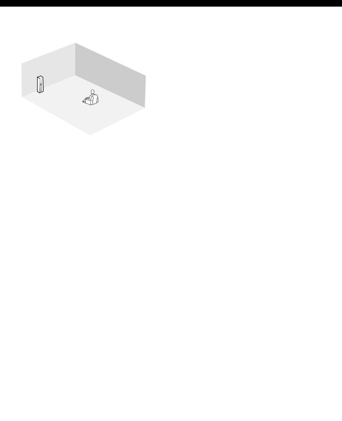
Connections
■ 7.2/7.1 (or 6.2/6.1) -channel speaker layout |
■ 5.2/5.1 -channel speaker layout |
See page 23 for connection information. |
See page 23 for connection information. |
|
FR |
FR |
|
FL |
RSW |
RSW |
|
SR |
FL |
||
|
C |
C |
|
|
SL |
SR |
|
LSW |
LSW |
||
|
|||
|
|
SBR |
|
|
SBL |
SL |
|
|
|
|
C |
|
Speaker indications |
|
C |
|
Speaker indications |
FL |
FR |
|
FL |
FR |
|
||
|
FL/FR: Front left/right |
|
FL/FR: Front left/right |
||||
|
|
|
|
|
|
||
|
30˚ |
|
C: Center |
|
30˚ |
|
C: Center |
|
|
SL/SR: Surround left/right |
|
|
SL/SR: Surround left/right |
||
|
|
|
|
|
|
||
SL |
|
SR |
SBL/SBR: Surround back |
SL |
|
SR |
LSW/RSW: Left/right subwoofer |
|
left/right |
|
|
||||
SL |
60˚ |
SR |
SL |
60˚ |
SR |
|
|
80˚ |
LSW/RSW: Left/right subwoofer |
80˚ |
|
||||
|
|
|
|
|
|||
|
SBL |
SBR |
|
|
|
|
|
|
|
|
|
|
|
||
30 cm (12 in) or more |
|
|
|
|
|
||
Front left and right speakers Center speaker
Surround left and right speakers
The functions and settings of each speaker are the same as those for the 11.2/11.1-channel speaker layout (see page 21).
Surround back left and right speakers
The surround back speakers supplement the surround speakers and provide more realistic front-to-back transitions.
If you use a single surround back speaker, connect the single surround back speaker to the SUR.BACK/BI-AMP (SINGLE) speaker terminal and place the speaker behind the listening position. The surround back left and right channel signals are mixed down and output at the single surround back speaker when you set “Surround Back” to “Small x1” or “Large x1” (see page 84).
Subwoofer
See page 25 for details.
y
You can also use the front presence speakers (see page 26) instead of the surround back speakers.
Front left and right speakers Center speaker
Subwoofer
The functions and settings of each speaker are the same as those for the 11.2/11.1-channel speaker layout (see page 21).
Surround left and right speakers
Connect the surround speakers to the SURROUND speaker terminals even if you place the surround speakers behind the listening position. For the smooth and unbroken sound field behind the listening position, place the surround left and right speakers farther back compared with the placement in the 11.2/11.1-channel speaker layout. The surround back channel signals are directed to the surround left and right speakers when “Surround Back” is set to “None” (see page 84).
Subwoofer
See page 25 for details.
For other speaker combinations
You can enjoy multi-channel sources with sound field programs by using a speaker combination other than the speaker combinations shown above.
Use the automatic setup feature (see page 42) or set the “Speaker Set” parameters in “Manual Setup” (see page 84) to output the surround sounds at the connected speakers.
22 En
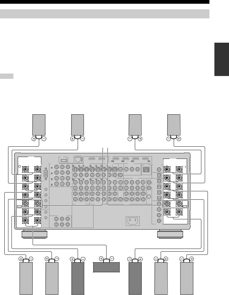
Connections
Connecting speakers
Be sure to connect the left channel (L), right channel (R), “+” (red line) and “–” (white line) properly. If the connections are faulty, this unit cannot reproduce the input sources accurately.
Caution |
|
|
• Before connecting the speakers, make sure that this unit is turned off (see page 39). |
|
|
• Do not let the bare speaker wires touch each other or do not let them touch any metal part of this unit. This could damage this unit and/ |
|
|
|
||
or speakers. |
|
Preparation |
• Use magnetically shielded speakers. If this type of speaker still creates interference with the monitor, place the speakers away from the |
|
|
|
|
|
monitor. |
|
|
• If you are to use 6-ohm speakers, be sure to set “SPEAKER IMP.” to “6ΩMIN” before using this unit (see page 39). |
|
|
|
|
|
Notes
•A speaker cord is actually a pair of insulated cables running side by side. Cables are colored or shaped differently, perhaps with a stripe, groove or ridge. Connect the striped (grooved, etc.) cable to the “+” (red line) terminals on this unit and your speaker. Connect the plain cable to the “–” (white line) terminals.
•You can use the REAR ZONE/PRESENCE, FRONT ZONE/PRESENCE, and/or EXTRA SP speaker terminals for the Zone 2, Zone 3, and/or Zone 4 speakers (see page 116). You can also use all speaker terminals on this unit for the Zone 2, Zone 3, and/or Zone 4 speakers (see page 120).
■ For the 11.2/11.1 (or 9.2/9.1) -channel speaker setting
Right front |
Right rear |
Left rear |
Left front |
presence |
presence |
presence |
presence |
speaker |
speaker |
speaker |
speaker |
|
|
|
|
|
|
|
|
|
FRONT B speakers |
|
|
|
|
|
|
|
|
|
||||||
SPEAKERS |
|
|
|
USB |
|
NETWORK |
|
|
|
|
|
|
HDMI |
|
|
|
|
|
|
|
|
|
|
|
|
|
|
|
|
|
|
|
|
|
|
|
|
|
|
|
|
|
|
|
|
|
|
|
SPEAKERS |
|
|
|
|
|
|
|
|
OUT 1 |
|
OUT 2 |
IN1 |
IN2 |
|
IN3 |
|
|
IN4 |
|
|
|
||||
|
RS-232C |
COMPONENT VIDEO |
|
|
|
|
BD/HD DVD |
DVD |
CBL/SAT |
|
|
DVR |
|
|
|
|||||||||
|
|
S VIDEO |
VIDEO IN |
|
|
|
VIDEO OUT |
|
|
ZONE OUT |
|
DOCK |
DIGITAL OUT |
|
|
|||||||||
+ |
|
BD/ |
Y |
PB |
PR |
|
|
|
|
|
|
MONITOR |
VIDEO |
|
COMPONENT VIDEO |
|
+ |
|||||||
R |
|
HD DVD |
|
|
|
1 DVD |
2 DTV |
3 CBL/SAT |
4 DVR |
5 VCR |
4 DVR |
5 VCR |
OUT |
|
Y |
|
PB |
PR |
|
|
|
|
L |
|
REAR |
|
A |
|
|
|
|
|
|
|
|
|
|
|
|
|
|
|
|
|
|
|
|
|
REAR |
PRESENCE |
|
|
|
|
|
|
|
|
|
|
|
|
|
|
|
|
|
|
|
|
|
ZONE |
|
PRESENCE |
/ZONE |
|
|
|
|
|
|
|
|
|
|
|
|
|
|
|
|
|
|
|
|
|
COAXIAL |
|
/ZONE |
|
|
DVD |
|
|
|
|
|
|
|
|
|
|
|
|
|
|
|
|
|
|
|
|
|
|
|
|
|
|
|
|
|
|
|
|
|
|
|
|
|
|
|
|
|
|
|
CD-R |
|
|
|
|
|
B |
|
|
|
|
|
|
|
|
|
|
|
|
|
|
|
|
|
|
|
|
|
|
FRONT |
|
CBL/SAT |
|
|
VIDEO |
|
|
|
|
|
|
|
|
|
|
|
|
|
|
OPTICAL |
|
FRONT |
||
PRESENCE |
|
|
|
AUDIO IN |
|
|
|
|
AUDIO OUT |
|
|
|
AUDIO IN |
|
|
|
PRESENCE |
|||||||
|
C |
|
|
|
|
|
|
|
|
|
|
|
|
|
|
MD/TAPE |
|
|||||||
/ZONE |
|
|
|
|
1 DVD |
2 DTV |
3 CBL/SAT |
4 DVR |
5 VCR |
4 DVR |
5 VCR |
CD-R |
MD/TAPE |
CD-R |
|
MD/TAPE |
CD |
TUNER |
PHONO |
|
/ZONE |
|||
|
TRIGGER |
|
|
|
|
|
L |
1 |
|
|||||||||||||||
|
|
|
|
|
L |
|
|
|
|
|
|
|
|
|
|
|
|
|
|
|
|
|
||
|
OUT |
DVR |
|
|
|
|
|
|
|
|
|
|
|
|
|
|
|
|
|
|
|
|
|
|
|
|
|
|
|
|
|
|
|
|
|
|
|
|
|
|
|
|
|
|
|
|
|
|
|
|
|
D |
|
|
|
|
|
|
|
|
|
|
|
|
|
|
|
|
|
|
|
DVD |
|
|
SURROUND |
|
|
|
|
|
|
|
|
|
|
|
|
|
|
|
|
|
|
|
|
|
R |
2 |
SURROUND |
|
|
|
|
|
R |
|
|
|
|
|
|
|
|
|
|
|
|
|
|
|
|
|||
|
|
|
|
|
|
|
|
|
|
|
|
|
|
|
|
|
|
|
|
|
|
|
|
|
|
1 |
|
|
|
|
|
|
|
|
|
|
|
|
|
|
|
|
|
|
|
|
CBL/SAT |
|
|
|
+12v |
|
|
|
|
FRONT (6CH) |
|
CENTER |
|
|
|
|
|
|
|
(FRONT) |
|
(SINGLE) |
|
|
|
|
|
|
|
|
|
|
|
|
|
|
|
|
|
|
|
|
|
|
|
|
|
|
|||||
|
15mA MAX. |
|
|
|
|
L |
|
|
|
|
|
|
|
|
|
|
|
|
|
|
L |
|
3 |
(SINGLE) |
SUR. BACK/ |
|
|
|
|
|
|
|
|
|
|
|
|
|
|
|
|
|
|
|
|
|
SUR. BACK/ |
||
2 |
|
|
|
|
|
|
|
|
|
|
|
|
|
|
|
|
|
|
|
|
|
|
||
BI-AMP |
|
|
|
|
|
|
|
|
|
|
|
|
|
|
|
|
|
|
|
|
|
DVR |
|
BI-AMP |
|
REMOTE |
|
|
|
|
R |
|
|
|
|
|
|
|
|
|
|
|
|
|
|
R |
|
4 |
|
|
|
|
|
|
|
|
|
|
|
|
|
|
|
|
|
|
|
|
|
OPTICAL |
|
|
||
|
IN |
|
|
|
|
|
|
|
|
|
|
|
|
|
|
|
|
|
|
|
|
|
|
|
FRONT B |
|
|
|
|
|
SB (8CH) |
SURROUND SUBWOOFER |
ZONE 2 |
ZONE 3 |
ZONE 4 |
|
FRONT |
SURROUND |
CENTER |
(REAR) |
|
SUR. BACK |
FRONT |
REAR |
|
CD |
|
FRONT B |
|
1 |
|
|
|
|
|
SUBWOOFER |
PRESENCE |
PRESENCE |
GND |
|
5 |
|||||||||||||
/ZONE |
|
|
|
|
|
MULTI CH INPUT |
|
ZONE OUT |
|
|
|
|
|
PRE OUT |
|
|
|
|
|
/ZONE |
||||
EXTRA SP |
OUT |
|
|
|
|
|
AC OUTLET |
|
|
|
|
|
|
|
|
|
|
|
|
|
|
|
EXTRA SP |
|
|
|
|
|
|
|
|
|
|
|
|
|
|
|
|
|
|
|
|
|
|
|
|||
|
|
|
|
|
|
|
|
|
|
|
|
|
|
|
|
|
|
|
|
|
|
BD/ |
6 |
|
|
|
|
|
|
|
|
|
|
|
|
|
|
|
|
|
|
|
|
|
|
|
HD DVD |
|
|
FRONT A |
IN |
|
|
|
|
|
|
|
|
|
|
|
|
|
|
|
|
|
|
|
|
|
|
FRONT A |
|
2 |
|
|
COMPONENT VIDEO |
|
|
|
|
|
|
|
|
|
|
|
|
AC IN |
|
|
|
DVD |
7 |
|
|
|
|
|
|
|
|
|
|
|
|
|
|
|
|
|
|
|
|
|
|
|
||||
|
OUT |
|
Y |
PB |
PR |
|
|
|
|
|
|
|
|
|
|
|
|
|
|
|
|
|
|
|
|
1 |
|
|
|
|
|
|
|
|
|
|
|
|
|
|
|
|
|
|
|
|
|
|
|
|
|
|
|
|
|
|
|
|
|
|
|
|
|
|
|
|
|
|
|
|
|
|
|
|
CENTER |
|
MONITOR |
|
|
|
|
|
|
|
|
|
|
|
|
|
|
|
|
|
|
|
DTV |
8 |
|
|
|
|
|
|
|
|
|
|
|
|
|
|
|
|
|
|
|
|
|
|
|
|
||
|
|
OUT |
|
|
|
|
|
|
|
|
|
|
|
|
|
|
|
|
|
|
|
COAXIAL |
|
|
|
|
2 |
|
|
|
|
|
|
|
|
|
|
|
|
|
|
|
|
|
|
|
DIGITAL IN |
|
|
Center speaker
Surround right |
Surround back |
Front right |
Front left |
Surround back |
Surround left |
speaker |
right speaker |
speaker |
speaker |
left speaker |
speaker |
23 En
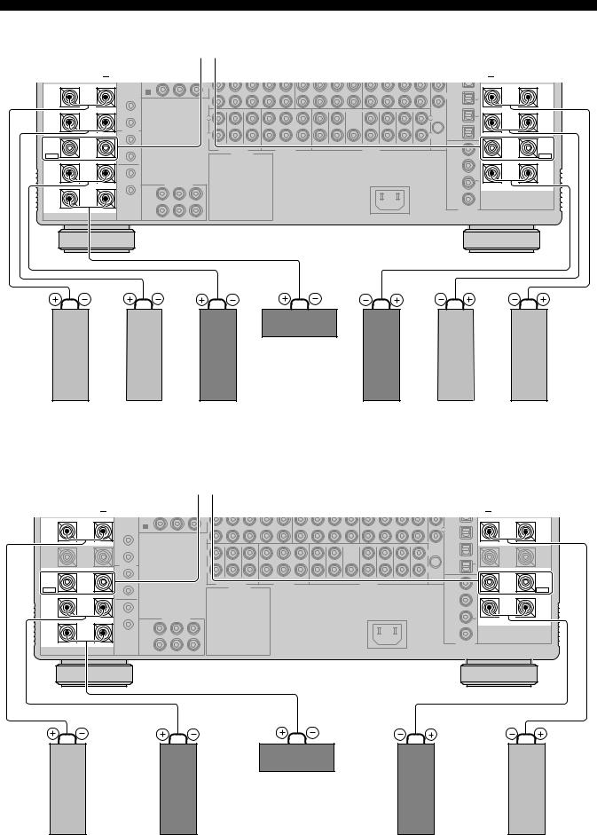
Connections
■ For the 7.2/7.1 (or 6.2/6.1) -channel speaker setting
|
|
|
FRONT B speakers |
|
|
|
|
|
|
|
|
|
|
|
|
|
||
|
+ |
|
|
|
|
|
|
|
|
|
|
|
|
|
|
|
|
+ |
|
OUT |
DVR |
|
L |
|
|
|
|
|
|
|
|
|
|
|
|
|
|
|
|
|
|
|
|
|
|
|
|
|
|
|
|
|
|
|
|
|
|
|
D |
|
|
|
|
|
|
|
|
|
|
|
|
|
DVD |
|
|
SURROUND |
|
|
|
|
|
|
|
|
|
|
|
|
|
|
|
R |
2 |
SURROUND |
|
|
|
R |
|
|
|
|
|
|
|
|
|
|
|
|
|||
|
|
|
|
|
|
|
|
|
|
|
|
|
|
|
|
|
|
|
|
1 |
|
|
|
|
|
|
|
|
|
|
|
|
|
|
CBL/SAT |
|
|
|
+12v |
|
|
FRONT (6CH) |
CENTER |
|
|
|
|
|
|
(FRONT) |
(SINGLE) |
|
|
|
|
|
|
|
|
|
|
|
|
|
|
|
|
|
3 |
|
|||||
|
15mA MAX. |
|
|
L |
|
|
|
|
|
|
|
|
|
|
|
L |
(SINGLE) |
|
SUR. BACK/ |
|
|
|
|
|
|
|
|
|
|
|
|
|
|
|
SUR. BACK/ |
||
2 |
|
|
|
|
|
|
|
|
|
|
|
|
|
|
|
|
||
BI-AMP |
|
|
|
|
|
|
|
|
|
|
|
|
|
|
|
DVR |
|
BI-AMP |
|
REMOTE |
|
|
R |
|
|
|
|
|
|
|
|
|
|
|
R |
4 |
|
|
|
|
|
|
|
|
|
|
|
|
|
|
|
|
|
|
||
|
IN |
|
|
|
|
|
|
|
|
|
|
|
|
|
|
OPTICAL |
|
|
FRONT B |
|
|
|
SB (8CH) |
SURROUND SUBWOOFER |
ZONE 2 |
ZONE 3 |
ZONE 4 |
FRONT |
SURROUND |
CENTER |
(REAR) |
SUR. BACK |
FRONT |
REAR |
CD |
|
FRONT B |
1 |
|
|
SUBWOOFER |
PRESENCE |
PRESENCE |
GND |
5 |
|||||||||||
/ZONE |
|
|
|
MULTI CH INPUT |
|
ZONE OUT |
|
|
|
|
PRE OUT |
|
|
|
|
/ZONE |
||
EXTRA SP |
OUT |
|
|
|
AC OUTLET |
|
|
|
|
|
|
|
|
|
|
|
|
EXTRA SP |
|
|
|
|
|
|
|
|
|
|
|
|
|
|
|
|
|||
|
|
|
|
|
|
|
|
|
|
|
|
|
|
|
|
BD/ |
6 |
|
|
|
|
|
|
|
|
|
|
|
|
|
|
|
|
|
HD DVD |
|
|
FRONT A |
IN |
|
|
|
|
|
|
|
|
|
|
|
|
|
|
|
|
FRONT A |
|
2 |
|
COMPONENT VIDEO |
|
|
|
|
|
|
|
|
AC IN |
|
|
DVD |
7 |
|
|
|
OUT |
Y |
PB |
PR |
|
|
|
|
|
|
|
|
|
|
|
|
|
|
|
1 |
|
|
|
|
|
|
|
|
|
|
|
|
|
|
|
|
|
|
|
|
|
|
|
|
|
|
|
|
|
|
|
|
|
|
|
|
CENTER |
|
MONITOR |
|
|
|
|
|
|
|
|
|
|
|
|
|
DTV |
8 |
|
|
|
|
|
|
|
|
|
|
|
|
|
|
|
|
|
|
||
|
|
OUT |
|
|
|
|
|
|
|
|
|
|
|
|
|
COAXIAL |
|
|
|
|
2 |
|
|
|
|
|
|
|
|
|
|
|
|
|
DIGITAL IN |
|
|
Center speaker
Surround right |
Surround back |
Front right |
Front left |
Surround back |
Surround left |
speaker |
right speaker |
speaker |
speaker |
left speaker * |
speaker |
* If you use a single surround back speaker, connect the speaker to the SUR.BACK/BI-AMP (SINGLE) speaker terminal.
■ For the 5.2/5.1 -channel speaker setting |
|
|
|
|
|
|
|
|
|
|
|
|
|||||
|
|
|
FRONT B speakers |
|
|
|
|
|
|
|
|
|
|
|
|
||
|
+ |
|
|
|
|
|
|
|
|
|
|
|
|
|
|
|
+ |
|
OUT |
DVR |
|
L |
|
|
|
|
|
|
|
|
|
|
|
|
|
|
|
|
|
|
|
|
|
|
|
|
|
|
|
|
|
|
|
|
|
D |
|
|
|
|
|
|
|
|
|
|
|
|
DVD |
|
|
SURROUND |
|
|
|
|
|
|
|
|
|
|
|
|
|
|
R |
2 |
SURROUND |
|
|
|
R |
|
|
|
|
|
|
|
|
|
|
|
|||
|
|
|
|
|
|
|
|
|
|
|
|
|
|
|
|
|
|
|
1 |
|
|
|
|
|
|
|
|
|
|
|
|
|
CBL/SAT |
|
|
|
+12v |
|
|
FRONT (6CH) |
CENTER |
|
|
|
|
|
(FRONT) |
(SINGLE) |
|
|
|
|
|
|
15mA MAX. |
|
|
L |
|
|
|
|
|
|
|
|
|
|
L |
3 |
(SINGLE) |
SUR. BACK/ |
|
|
|
|
|
|
|
|
|
|
|
|
|
|
SUR. BACK/ |
||
2 |
|
|
|
|
|
|
|
|
|
|
|
|
|
|
|
||
BI-AMP |
|
|
|
|
|
|
|
|
|
|
|
|
|
|
DVR |
|
BI-AMP |
|
REMOTE |
|
|
R |
|
|
|
|
|
|
|
|
|
|
R |
4 |
|
|
|
|
|
|
|
|
|
|
|
|
|
|
|
|
|
||
|
IN |
|
|
|
|
|
|
|
|
|
|
|
|
|
OPTICAL |
|
|
FRONT B |
|
|
|
SB (8CH) |
SURROUND SUBWOOFER ZONE 2 |
ZONE 3 |
ZONE 4 |
FRONT |
SURROUND |
CENTER |
(REAR) |
SUR. BACK |
FRONT |
REAR |
CD |
|
FRONT B |
1 |
|
|
SUBWOOFER |
PRESENCE |
PRESENCE |
GND |
5 |
||||||||||
/ZONE |
|
|
|
MULTI CH INPUT |
ZONE OUT |
|
|
|
|
PRE OUT |
|
|
|
|
/ZONE |
||
EXTRA SP |
OUT |
|
|
|
AC OUTLET |
|
|
|
|
|
|
|
|
|
|
|
EXTRA SP |
|
|
|
|
|
|
|
|
|
|
|
|
|
|
|
|||
|
|
|
|
|
|
|
|
|
|
|
|
|
|
|
BD/ |
6 |
|
|
|
|
|
|
|
|
|
|
|
|
|
|
|
|
HD DVD |
|
|
FRONT A |
IN |
|
|
|
|
|
|
|
|
|
|
|
|
|
|
|
FRONT A |
|
2 |
|
COMPONENT VIDEO |
|
|
|
|
|
|
|
AC IN |
|
|
DVD |
7 |
|
|
|
OUT |
Y |
PB |
PR |
|
|
|
|
|
|
|
|
|
|
|
|
|
|
1 |
|
|
|
|
|
|
|
|
|
|
|
|
|
|
|
|
|
|
|
|
|
|
|
|
|
|
|
|
|
|
|
|
|
|
CENTER |
|
MONITOR |
|
|
|
|
|
|
|
|
|
|
|
|
DTV |
8 |
|
|
|
OUT |
|
|
|
|
|
|
|
|
|
|
|
|
COAXIAL |
|
|
|
|
2 |
|
|
|
|
|
|
|
|
|
|
|
|
DIGITAL IN |
|
|
Center speaker
Surround right |
Front right |
Front left |
Surround left |
speaker |
speaker |
speaker |
speaker |
24 En
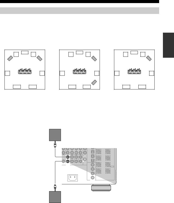
Connections
Using subwoofers
The use of subwoofers with built-in amplifiers, such as the Yamaha Active Servo Processing Subwoofer System, is effective not only for reinforcing bass frequencies from any or all channels, but also for reproducing the high fidelity sound of the LFE (low-frequency effect) channel included in digital audio signals. Turn it slightly toward the center of the room to reduce wall reflections.
You can use one or two subwoofers and select various positions of the subwoofers.
■ Configuration 1:
Front left and right
Set “Configuration” in “Subwoofer” to “Stereo” (see page 85).
|
C |
FL |
FR |
LSW |
RSW |
SL |
SR |
SBL |
SBR |
■Configuration 2: Front and rear
Set “Configuration” in “Subwoofer” to |
|
“Front & Rear” (see page 85). |
|
|
C |
FL |
FR |
|
FSW |
SL |
SR |
|
RSW |
SBL |
SBR |
■ Configuration 3:
A single subwoofer
Set “Configuration” in “Subwoofer” to “Monaural” (see page 85).
|
C |
FL |
FR |
|
SW |
SL |
SR |
SBL |
SBR |
Speaker indications |
Speaker indications |
Speaker indications |
FL/FR: Front left/right |
FL/FR: Front left/right |
FL/FR: Front left/right |
C: Center |
C: Center |
C: Center |
SL/SR: Surround left/right |
SL/SR: Surround left/right |
SL/SR: Surround left/right |
SBL/SBR: Surround back left/right |
SBL/SBR: Surround back left/right |
SBL/SBR: Surround back left/right |
LSW/RSW: Left/right subwoofer |
FSW/RSW: Front/rear subwoofer |
SW: Subwoofer |
■ Connecting subwoofers
Left (or front) subwoofer y
If you connect a single subwoofer, connect the subwoofer to the left SUBWOOFER PRE OUT jacks.
|
|
|
|
|
DVD |
|
|
|
|
|
|
|
R |
2 |
SURROUND |
|
|
|
|
|
|
||
|
(FRONT) |
(SINGLE) |
|
|
CBL/SAT |
|
|
|
|
|
|
|
L |
3 |
(SINGLE) |
|
|
|
|
|
|
SUR. BACK/ |
|
|
|
|
|
|
|
|
|
|
|
|
|
|
DVR |
|
BI-AMP |
|
|
|
|
|
R |
4 |
|
|
|
|
|
|
|
|
|
|
|
|
|
|
OPTICAL |
|
|
CENTER |
(REAR) |
SUR. BACK |
FRONT |
REAR |
CD |
|
FRONT B |
GND |
|
||||||
SUBWOOFER |
PRESENCE |
PRESENCE |
5 |
||||
|
PRE OUT |
|
|
|
|
/ZONE |
|
|
|
|
|
|
|
|
EXTRA SP |
|
|
|
|
|
BD/ |
6 |
|
|
|
|
|
|
HD DVD |
|
|
|
|
|
|
|
|
|
FRONT A |
|
|
AC IN |
|
|
DVD |
7 |
|
DTV 8
COAXIAL
DIGITAL IN
Right (or rear) subwoofer
Preparation
25 En
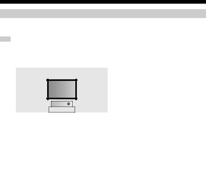
Connections
Using presence speakers
The presence speakers supplement the sound from the front and surround back speakers with extra ambient effects produced by the sound field programs (see page 54). Presence speakers function more effectively when the CINEMA DSP HD³ mode is active (see page 60). You can adjust the vertical position of dialogues with using the front presence speakers (see page 77).
Note
If “Front Presence” is set to “None”, the rear presence speakers also do not function and you cannot activate the CINEMA DSP HD³ mode.
Front presence speakers
0.5 to 1 m (1 to 3 ft) |
0.5 to 1 m (1 to 3 ft) |
|
|
|
|
Speaker indications |
|
FPL |
FPR |
|
FL: Front left |
|
|
FR: Front right |
||
|
|
|
|
|
|
|
|
|
C: Center |
|
|
|
|
FPL: Front presence left |
1.8 m |
FL |
FR |
1.8 m |
FPR: Front presence right |
(6 ft) or |
(6 ft) or |
|
||
higher |
|
|
higher |
|
|
|
C |
|
|
|
|
* |
|
|
Rear presence speakers |
|
|
|
|
|
RPR |
RPL |
|
Speaker indications |
|
|
SL: Surround left |
||
|
|
|
|
|
|
1.8 m |
1.8 m |
|
SR: Surround right |
|
|
SBL: Surround back left |
||
|
(6 ft) or |
(6 ft) or |
|
|
|
|
SBR: Surround back right |
||
|
higher |
higher |
|
|
SR |
|
|
SL |
RPL: Rear presence left |
SBR |
SBL |
RPR: Rear presence right |
||
|
|
|
||
|
|
* |
|
|
*Place the rear presence left and right speakers so that the distance between the rear presence left and right speakers is same as the distance between front presence left and right speakers.
26 En
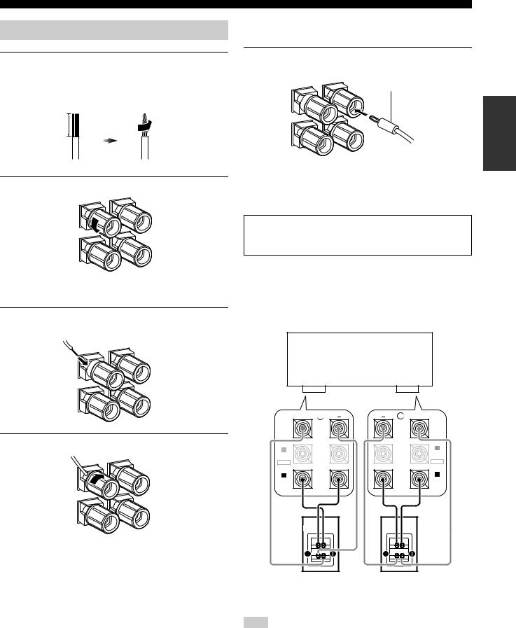
Connecting the speaker cable
1Remove approximately 10 mm (0.4 in) of insulation from the end of each speaker cable and then twist the exposed wires of the cable together to prevent short circuits.
10 mm (0.4 in)
2 Loosen the knob.
Red line: positive (+)
White line: negative (–)
3Insert one bare wire into the hole on the side of each terminal.
Connections
■Connecting the banana plug (China and General models only)
Tighten the knob and then insert the banana plug connector into the end of the corresponding terminal.
banana plug
Preparation
Red line: positive (+)
White line: negative (–)
■ Using bi-amplification connections
Caution
Remove the shorting bars or bridges of your speakers to separate the LPF (low pass filter) and HPF (high pass filter) crossovers.
This unit allows you to make bi-amplification connections to one speaker system. Check if your speakers support bi-amplification. To make the bi-amplification connections, use the FRONT A and SUR.BACK/BI-AMP terminals as shown below. To activate the biamplification connections, set “BI-AMP” to “ON” in “Advanced setup” (see page 120).
This unit
4 Tighten the knob to secure the wire.
+ |
R |
L |
+ |
|
|
|
(SINGLE) |
SUR. BACK/ |
|
|
SUR. BACK/ |
BI-AMP |
|
|
BI-AMP |
B |
|
|
B |
|
|
FRONT B/ |
|
FRONT B/ |
|
|
|
|
|
ZONE |
|
ZONE |
|
|
|
EXTRA SP |
|
|
EXTRA SP |
|
|
|
FRONT B/ |
A |
|
|
A |
FRONT A |
|
|
FRONT A |
Right |
Left |
Front speakers
Note
When you make the conventional connection, make sure that the shorting bars are put into the terminals of the speakers appropriately. Refer to the instruction manuals of the speakers for details.
27 En
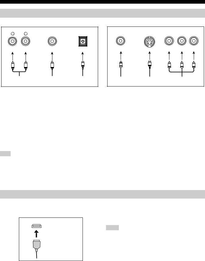
Connections
Information on jacks and cable plugs
Audio jacks and cable plugs
AUDIO |
DIGITAL |
DIGITAL |
|
L |
R |
COAXIAL |
OPTICAL |
(White) |
(Red) |
(Orange) |
|
L |
R |
C |
O |
|
|||
Left and right analog |
Coaxial digital |
Optical digital |
|
audio cable plugs |
audio cable plug |
audio cable plug |
|
■ Audio jacks
This unit has three types of audio jacks. Connection depends on the availability of audio jacks on your other components.
AUDIO jacks
For conventional analog audio signals transmitted via left and right analog audio cables. Connect red plugs to the right jacks and white plugs to the left jacks.
DIGITAL COAXIAL jacks
For digital audio signals transmitted via coaxial digital audio cables.
DIGITAL OPTICAL jacks
For digital audio signals transmitted via optical digital audio cables.
Note
You can use the digital jacks to input PCM, Dolby Digital and DTS bitstreams. When you connect components to both the COAXIAL and OPTICAL jacks, priority is given to the signals input at the COAXIAL jack. All digital input jacks are compatible with 96-kHz sampling digital signals.
Information on HDMI™
■ HDMI jack and cable plug
This unit has five HDMI input jacks and two HDMI output jacks for digital audio and video signal input/output.
HDMI
HDMI cable plug
y
•We recommend that you use a commercially available HDMI cable shorter than 5 meters (16 feet) with the HDMI logo printed on it.
•Use a conversion cable (HDMI jack ↔DVI-D jack) to connect this unit to other DVI components.
•You can check the potential problem about the HDMI connection (see page 95).
Video jacks and cable plugs
|
|
COMPONENT VIDEO |
||
VIDEO |
S VIDEO |
Y |
PB |
PR |
(Yellow) |
|
(Green) |
(Blue) |
(Red) |
V |
S |
Y |
PB |
PR |
|
||||
Composite video |
S-video cable |
Component video |
||
cable plug |
plug |
cable plugs |
|
|
■ Video jacks
This unit has three types of video jacks. Connect the video input jacks on this unit to the video output jacks of the input source components to switch the audio and video sources simultaneously. Connection depends on the availability of input jacks on your video monitor.
VIDEO jacks
For conventional composite video signals transmitted via composite video cables.
S VIDEO jacks
For S-video signals, separated into the luminance (Y) and chrominance (C) video signals transmitted on separate wires of S- video cables.
COMPONENT VIDEO jacks
For component video signals, separated into the luminance (Y) and chrominance (PB, PR) video signals transmitted on separate wires of component video cables.
y
This unit is equipped with the video conversion function. See pages 29 and 89 for details.
•See page 139 for the information on the input signal capability of this unit for the HDMI connection.
•When you set “Standby Through” in “Manual Setup” to “On”, this unit allows the HDMI signals input at an HDMI IN jack to pass through this unit and output at an HDMI OUT jack (see page 94).
Notes
•Do not disconnect or connect the cable or turn off the power of the HDMI components connected to the HDMI OUT jacks on this unit while data is being transferred. Doing so may disrupt playback or cause noise.
•The HDMI OUT jacks output the audio signals input at the HDMI input jacks only when “Support Audio” is set to “Other” (see page 94).
•If you turn off the power of the video monitor connected to the HDMI OUT jacks via a DVI connection, this unit may fail to establish the connection to the component.
•The analog video signals input at the composite video, S-video and component video jacks can be digitally up-converted to be output at the HDMI OUT jacks. Set “Conversion” to “On” in “Manual Setup” (see page 89) to activate this feature.
•This unit is equipped with two HDMI OUT jacks, however cannot output the video signals to the both HDMI OUT jacks simultaneously. You can select the active HDMI OUT jack. See page 50 for details.
28 En
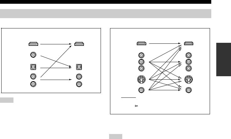
Audio and video signal flow
■ Audio signal flow
Input |
Output |
HDMI
DIGITAL AUDIO (COAXIAL)
DIGITAL AUDIO (OPTICAL)
AUDIO
Notes
•2-channel as well as multi-channel PCM, Dolby Digital and DTS signals input at the HDMI input jacks can be output at the HDMI OUT jacks only when “Support Audio” is set to “Other” (see page 94).
•The following types of audio signals can be only input at HDMI input jacks:
–DSD
–Dolby TrueHD
–Dolby Digital Plus
–DTS-HD Master Audio
–DTS-HD High Resolution Audio
Connections
■ Video signal flow
Input |
Output |
|
HDMI |
Preparation |
|
COMPONENT |
||
|
||
VIDEO |
|
SVIDEO
VIDEO
 Through
 “Conversion”: “On” (see page 89)
y
You can deinterlace and convert the resolution of the video signals by using “Video” parameters. See page 89 for details.
Notes
•When the analog video signals are input at the COMPONENT VIDEO, S VIDEO and VIDEO jacks, the priority order of the input signals is as follows:
1.COMPONENT VIDEO
2.S VIDEO
3.VIDEO
•This unit is equipped with the two COMPONENT VIDEO MONITOR OUT jacks and HDMI OUT jacks. The COMPONENT VIDEO MONITOR OUT 1 and 2 outputs the same video signals and you can use both COMPONENT VIDEO OUT jacks simultaneously.
•Digital video signals input at the HDMI input jacks cannot be output from analog video output jacks.
•The analog component video signals (with 480i (NTSC)/576i (PAL) of resolution only) are converted to the S-video or composite video signals and output at the VIDEO or S VIDEO MONITOR OUT jacks.
•The GUI signal is not output at the DVR OUT and VCR OUT jacks and is not recorded.
29 En
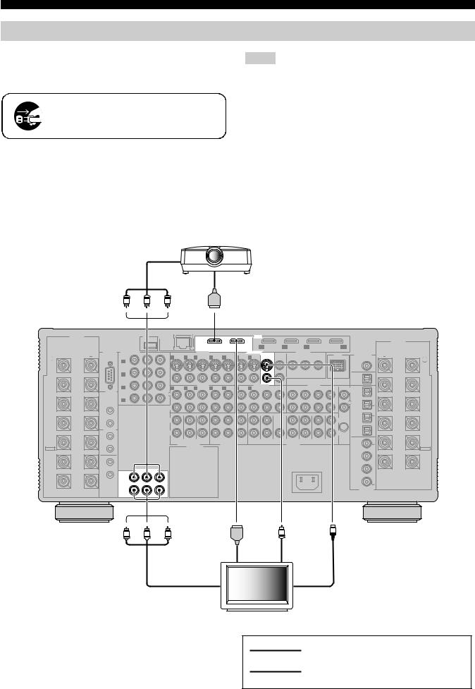
Connections
Connecting a TV monitor or projector
Connect your TV (or projector) to one of the HDMI OUT jacks, the COMPONENT VIDEO MONITOR OUT jacks, the S VIDEO MONITOR OUT jack or the VIDEO MONITOR OUT jack of this unit.
Make sure that this unit and other components are unplugged from the AC wall outlets.
y
You can select to play back HDMI audio signals on this unit or on another HDMI component connected to the HDMI OUT jacks on the rear panel of this unit. Use the “Support Audio” parameter in “Option” to select the component to play back HDMI audio signals (see page 94).
Component video in
Notes
•This unit is equipped with two HDMI OUT jacks, however cannot output the video signals to the both HDMI OUT jacks simultaneously. You can select the active HDMI OUT jack. Set the operation mode selector to FAMP and then press CHDMI OUT repeatedly.
•If you connect a video monitor or projector to one of the HDMI OUT jack, connect the component to the HDMI OUT 1 jack.
•Some video monitors connected to this unit via a DVI connection fail to recognize the HDMI audio/video signals being input if they are in the standby mode. In this case, the HDMI indicator flashes irregularly.
•The GUI menu is not overlaid on the input video image depending on the input video signal format and the setting of the parameters in “Wall Paper” (see page 91). In this case, the GUI menu appears with the wall paper or gray background.
•If the connected video monitor is compatible with the automatic audio and video synchronization feature (automatic lip sync feature), this unit adjusts the audio and video timing automatically (see page 88). Connect the video monitor to the HDMI OUT jacks on this unit to use the feature.
Projector
|
|
|
|
|
|
|
|
|
|
HDMI in |
|
|
|
|
|
|
|
|
|
|
|
|
||
|
|
Y |
|
PB |
|
PR |
|
|
|
|
|
|
|
|
|
|
|
|
|
|
|
|
|
|
|
SPEAKERS |
|
|
USB |
|
NETWORK |
|
|
|
|
|
|
HDMI |
|
|
|
|
|
|
|
|
|
|
|
|
|
|
|
|
|
|
|
|
|
|
|
|
|
|
|
|
|
|
|
|
|
|
|
SPEAKERS |
|
|
|
|
|
|
|
|
OUT 1 |
|
OUT 2 |
IN1 |
IN2 |
|
IN3 |
|
|
IN4 |
|
|
|
||||
|
RS-232C |
COMPONENT VIDEO |
|
|
|
|
|
BD/HD DVD |
DVD |
CBL/SAT |
|
|
DVR |
|
|
|
||||||||
|
|
|
S VIDEO |
VIDEO IN |
|
|
|
VIDEO OUT |
|
|
ZONE OUT |
|
DOCK |
DIGITAL OUT |
|
|
||||||||
+ |
|
BD/ |
Y |
PB |
PR |
|
|
|
|
|
|
MONITOR |
VIDEO |
|
COMPONENT VIDEO |
|
+ |
|||||||
R |
|
HD DVD |
|
|
|
1 DVD |
2 DTV |
3 CBL/SAT |
4 DVR |
5 VCR |
4 DVR |
5 VCR |
OUT |
|
Y |
|
PB |
PR |
|
|
|
|
L |
|
REAR |
|
A |
|
|
|
|
|
|
|
|
|
|
|
|
|
|
|
|
|
|
|
|
|
REAR |
PRESENCE |
|
|
|
|
|
|
|
|
|
|
|
|
|
|
|
|
|
|
|
|
|
ZONE |
|
PRESENCE |
/ZONE |
|
|
|
|
|
|
|
|
|
|
|
|
|
|
|
|
|
|
|
|
|
COAXIAL |
|
/ZONE |
|
|
DVD |
|
|
|
|
|
|
|
|
|
|
|
|
|
|
|
|
|
|
|
|
|
|
|
|
|
|
|
|
|
|
|
|
|
|
|
|
|
|
|
|
|
|
|
CD-R |
|
|
|
|
|
B |
|
|
|
|
|
|
|
|
|
|
|
|
|
|
|
|
|
|
|
|
|
|
FRONT |
|
CBL/SAT |
|
|
VIDEO |
|
|
|
|
|
|
|
|
|
|
|
|
|
|
OPTICAL |
|
FRONT |
||
PRESENCE |
|
|
|
AUDIO IN |
|
|
|
|
AUDIO OUT |
|
|
|
AUDIO IN |
|
|
|
PRESENCE |
|||||||
|
C |
|
|
|
|
|
|
|
|
|
|
|
|
|
|
MD/TAPE |
|
|||||||
/ZONE |
|
|
|
|
1 DVD |
2 DTV |
3 CBL/SAT |
4 DVR |
5 VCR |
4 DVR |
5 VCR |
CD-R |
MD/TAPE |
CD-R |
|
MD/TAPE |
CD |
TUNER |
PHONO |
|
/ZONE |
|||
|
TRIGGER |
|
|
|
|
|
L |
1 |
|
|||||||||||||||
|
|
|
|
|
L |
|
|
|
|
|
|
|
|
|
|
|
|
|
|
|
|
|
||
|
OUT |
DVR |
|
|
|
|
|
|
|
|
|
|
|
|
|
|
|
|
|
|
|
|
|
|
|
|
|
|
|
|
|
|
|
|
|
|
|
|
|
|
|
|
|
|
|
|
|
|
|
|
|
D |
|
|
|
|
|
|
|
|
|
|
|
|
|
|
|
|
|
|
|
DVD |
|
|
SURROUND |
|
|
|
|
|
|
|
|
|
|
|
|
|
|
|
|
|
|
|
|
|
R |
2 |
SURROUND |
|
|
|
|
|
R |
|
|
|
|
|
|
|
|
|
|
|
|
|
|
|
|
|||
|
|
|
|
|
|
|
|
|
|
|
|
|
|
|
|
|
|
|
|
|
|
|
|
|
|
1 |
|
|
|
|
|
|
|
|
|
|
|
|
|
|
|
|
|
|
|
|
CBL/SAT |
|
|
|
+12v |
|
|
|
|
FRONT (6CH) |
|
CENTER |
|
|
|
|
|
|
|
(FRONT) |
|
(SINGLE) |
|
|
|
|
|
|
|
|
|
|
|
|
|
|
|
|
|
|
|
|
|
|
|
|
|
|
|||||
|
15mA MAX. |
|
|
|
|
L |
|
|
|
|
|
|
|
|
|
|
|
|
|
|
L |
|
3 |
(SINGLE) |
SUR. BACK/ |
|
|
|
|
|
|
|
|
|
|
|
|
|
|
|
|
|
|
|
|
|
SUR. BACK/ |
||
2 |
|
|
|
|
|
|
|
|
|
|
|
|
|
|
|
|
|
|
|
|
|
|
||
BI-AMP |
|
|
|
|
|
|
|
|
|
|
|
|
|
|
|
|
|
|
|
|
|
DVR |
|
BI-AMP |
|
|
|
|
|
|
|
|
|
|
|
|
|
|
|
|
|
|
|
|
|
|
|
|
|
|
REMOTE |
|
|
|
|
R |
|
|
|
|
|
|
|
|
|
|
|
|
|
|
R |
|
4 |
|
|
|
|
|
|
|
|
|
|
|
|
|
|
|
|
|
|
|
|
|
OPTICAL |
|
|
||
|
IN |
|
|
|
|
|
|
|
|
|
|
|
|
|
|
|
|
|
|
|
|
|
|
|
FRONT B |
|
|
|
|
|
SB (8CH) |
SURROUND SUBWOOFER |
ZONE 2 |
ZONE 3 |
ZONE 4 |
|
FRONT |
SURROUND |
CENTER |
(REAR) |
|
SUR. BACK |
FRONT |
REAR |
|
CD |
|
FRONT B |
|
1 |
|
|
|
|
|
SUBWOOFER |
PRESENCE |
PRESENCE |
GND |
|
5 |
|||||||||||||
/ZONE |
|
|
|
|
|
MULTI CH INPUT |
|
ZONE OUT |
|
|
|
|
|
PRE OUT |
|
|
|
|
|
/ZONE |
||||
EXTRA SP |
OUT |
|
|
|
|
|
AC OUTLET |
|
|
|
|
|
|
|
|
|
|
|
|
|
|
|
EXTRA SP |
|
|
|
|
|
|
|
|
|
|
|
|
|
|
|
|
|
|
|
|
|
|
|
|||
|
|
|
|
|
|
BD/ |
6 |
|
|
|
|
|
|
HD DVD |
|
FRONT A |
IN |
|
|
|
|
|
FRONT A |
|
2 |
|
COMPONENT VIDEO |
AC IN |
DVD |
7 |
|
|
|
|
|
||||
|
OUT |
Y |
PB |
PR |
|
|
|
|
1 |
|
|
|
|
|
|
|
|
|
|
|
|
|
|
CENTER |
|
MONITOR |
|
|
|
DTV |
8 |
|
|
|
|
|
|
||
|
|
OUT |
|
|
|
COAXIAL |
|
|
|
2 |
|
|
|
|
DIGITAL IN |
Y |
PB |
PR |
V |
S |
|
||||
|
|
HDMI in |
|
Video in |
|
|
Component video in |
|
S-video in |
|
|
|
TV |
|
indicates recommended connections
indicates alternative connections
30 En
Loading...