


MT44D
Table of contents
 Loading...
YAMAHA
MULTITRACK RECORDER
ENREGISTREUR MULTIPISTES
MEHRSPUR-REKORDER
MT44D
OPERATING MANUAL
MANUEL D’OPERATIONS
BEDIE NUNGSANLEITUNG
rr-T-i
YAMAHA
MT44D MULTITRACK RECORDER
PLAY PAUSE
- RECORDING LEVEL
TRK 2 THK 3 TRK 4
----
1 PITCH PHONES
Thank you for choosing the Yamaha MT44D Multitrack Cassette
Recorder.
The MT44D is a tremendous creative too! for musicians, com
posers, arrangers, recording enthusiasts, or people involved with
audio-visual production, it offers 4-channe! multitrack recording
capacility on standard compact cassettes, rnaking it easy to produce
professional-sOunding multitrack master tapes.
Built in Dolby B and Dolby C noise reduction systems mean dean,
high-quality recordings, while a logic-controlled transport with
forward and reverse cueing and useful auto locator functions let
you concentrate on creating, not on controlling the deck.
We urge you to read this manual thoroughly in order to get the
best possible performance from your MT44D.
Explanation of Graphical Symbolt
CA UT IO N
RISK OF ELECTRIC SHOCK
A
CAUTION; TO REDUCE THE RISK OF ELECTRIC
SHOCK, DO NOT REMOVE COVER (OR
BACK), NO USER-SERVICEABLE PARTS
INSIDE REFER SERVICING TO QUALI
FIED SERVICE PERSONNEL.
DO NOT OPEN
A
A
A
The lightning flash with arrowhead
symbol, within an equilateral triangle, is
intended to alert you to the presence of
uninsulated "dangerous voltage" within
the product's enclosure that may be of
sufficient magnitude to constitute a risk of
electric shock to persons.
The exclamation point within an
equilateral triangle is intended to alert you
to the presence of important operating
and maintenance (servicing) instructions in
the literature accompanying the appliance.
CONTENTS
PRECAUTIONS,.......................................................................................... 3
THE CONTROLSAND THEIR FUNCTIONS
MULTITRACK TECHNIQUES..................................................................... 7
SENSOR SEALS/HANDLING CASSETTE TAPES
SPECIFICATIONS
•ÉMiiillii
......................................................................................
.................................................
.....................................
4
9
10

PRECAUTIONS
• The MT44D functions as a standard stereo
cassette deck when loaded with any standard stereo
cassette tape. For four-channel multitrack record
ing a special sensor foil (supplied) must be affixed
to the cassette housing window.
• The MT44D is designed exclusively for use with
high-quality chrome-formulation cassette tape (High
Bias, 70 jU=sec EQ). Avoid C120 tape lengths because
the extreme thinness of the tape can result in
degraded sound quality and damage to the transport
system.
• To ensure a high signal-to-noise ratio and mini
mum distortion, the MT44D has a high-quality
permalloy reproduction head. Oxide flakes from
old tape and dust or dirt can impair the perform
ance of this head, so it should be cleaned regularly
with cotton buds and a tape head cleaning fluid, or
a head cleaning tape. The pinch roller should also
be cleaned at the same time.
• Locate the MT44D out of the direct rays of the
sun, also avoiding locations subject to vibration,
excessive dust, heat, cold or moisture.
• Irreparable damage may result from opening
the I\/1T44D cabinet or attempting to alter the
internal circuitry.
• Avoid dropping your MT44D or subjecting it
to any kind of shock, as impaired performance
may result.
• Do not attempt to clean any part of the MT44D
with chemical solvents (such as alcohol or benzine).
Wipe clean with a soft, dry cloth.
• The 50/60, Hz line frequency selector on the rear
of the MT44D must be set according to the fre
quency in your area in order for the tape counter
to read correct time.
CAUTION (PREPARED IN ACCORDANCE WITH UL STANDARD 1270)
1 Read Instructions — All the safety and operating
instructions shouid be read before the appliance is operated.
2 Retain Instructions — The safety and operating instruc
tions should be retained for future reference.
3 Head Warnings — All warnings on the appliance and in
the operating instructions should be adhered to.
4 Follow Instructions — All operating and other instruc
tions should be followed.
5 Water and Moisture — The appliance should not be used
near water — for example, near a bathtub, washbowl,
kitchen sink, laundry tub, in a wet basement, or near a
swimming pool, etc.
6 Carts and Stands — The appliance should be used only
with a cart or stand that is recommended by the manufac
turer.
7 Wall or Ceilling Mounting — The appliance should be
mounted to a wall or ceilling only as recommended by the
manufacturer.
8 Ventilation — The appliance should be situated so that
its location or position does not interfere with its proper
ventilation. For example, the appliance should not be
situated on a bed, sofa, rug, or similar surface that may
block the ventilation openings; or placed in a built-in
installation, such as a bookcase or cabinet that may impede
the flow of air through the ventilation openings.
9 Heat — The appliance should be situated away from
head sources such as radiators, stoves, or other appliances
that produce heat.
10 Power Sources — The appliance should be connected
to a power supply only of the type described in the operat
ing instructions or as marked on the appliance.
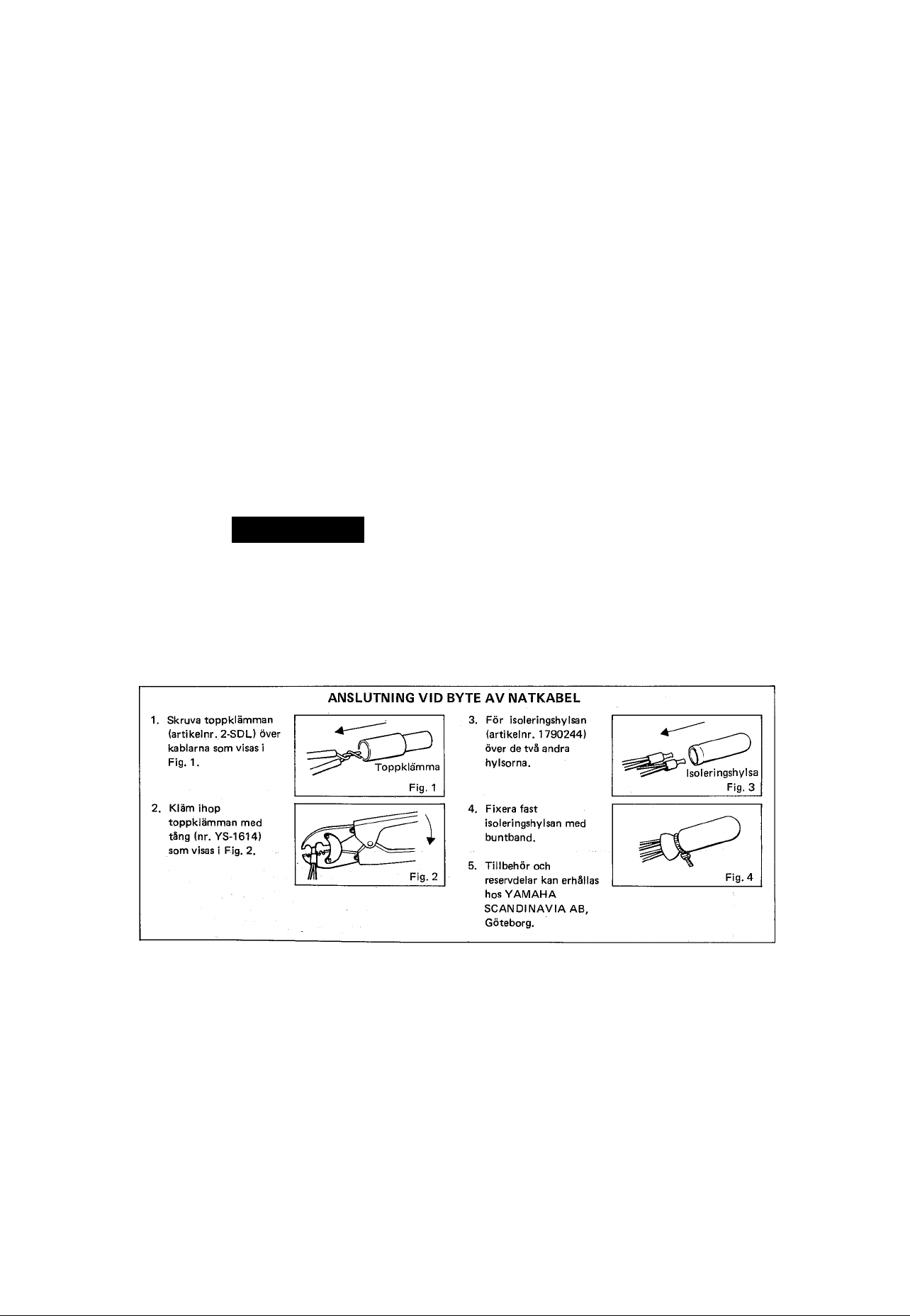
11 Power-Cord Protection — Power-supply cords should
be routed so that they are not likely to be walked on or
pinched by items placed upon or against them, paying
particular attention to cords at plugs, convenience
receptacles, and the point where they exit from the
appliance.
12 Cleaning — The appliance should be cleaned only as
recommended by the manufacturer.
13 Nonuse Periods — The power cord of the appliance
should be unplugged from the outlet when left unused for a
long period of time.
14 Object and Liquid Entry — Care should be taken so
that objects do not fall into and liquids not spilled into
the inside of the appliance.
15 Damage Requiring Service — The appliance should be
serviced by qualified service personnel when:
A. The power-supply cord or the plug has been damaged,
or
B. Objects have fallen, or liquid has been spilled into the
appliance; or
C. The appliance has been exposed to rain; or
D. The appliance does not appear to operate normally or
exhibits a marked change in performance; or
E. The appliance has been dropped, or the cabinet damag
ed.
16 Servicing — The user should not attempt to service the
appliance beyond those means described in the operating
instructions. All other servicing should be referred to
qualified service personnel.
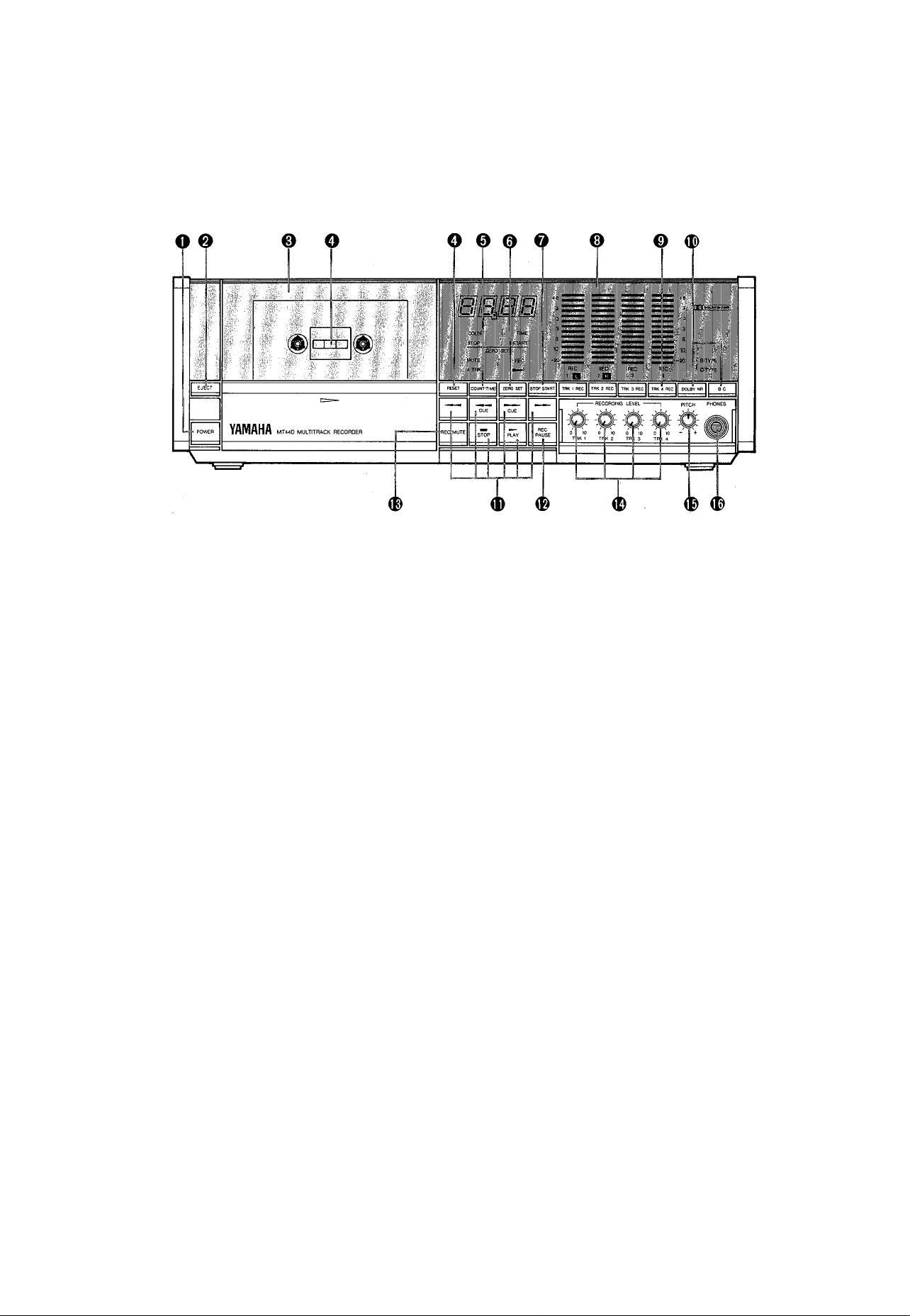
THE CONTROLS AND THEIR FUNCTIONS
FRONT PANEL
©POWER SWITCH
This switch turns AC power to the MT44D ON or
OFF. The LED tape counter will light to indicate
that the power has been turned ON.
©EJECT BUTTON
Pressing this button opens the cassette compartment
for ioading or unloading cassettes. Close the com
partment gently by hand after loading or unloading
a cassette.
* Never leave the cassette compartment open when
the IVIT44D is not in use. This prevents airborne
dust and dirt from entering the compa'^tment and
possibly affecting performance.
©DUAL MODE 4-DIGIT TAPE COUNTER
This large easy-to-read tape counter has two operat
ing modes', count and time. In the count mode it
functions like a conventional tape counter, indicat
ing tape position by a four-digit number. In the
count mode the counter "follows" tape motion in
the fast wind and cue modes as well as the play and
record modes.
In the time mode the counter indicates the amount
of time the tape has been running in the play or
record modes. The time function will not follow
tape motion in the fast wind or cue modes.
* The 50/60 FIz line frequency seiector on the rear
of the MT44D must be set according to the
frequency in your area in order for the tape
counter to read correct time.
©TAPE COUNTER RESET BUTTON
Pressing this button resets the tape counter to
"0000". The count and time functions are reset
separately: pressing reset while the counter is in
either mode resets only that mode.
©TAPE COUNTER COUNT/TIME MODE SELEC
TOR
This button selects the counter mode. The currently
engaged counter mode is indicated immediately
below the counter.
©TAPE COUNTER ZERO SET BUTTON
The Zero Set button must be turned ON to activate
the Zero-Start and Zero-Stop functions, described
below.
©TAPE COUNTER ZERO-START/ZERO-STOP
SELECTOR
When the Zero-Stop function is selected—the
STOP/START button is out—the tape will auto
matically stop when the counter "0000" point is
reached during rewind or rewind cue.
When the Zero-Start function is selected—the
STOP/START button is in—the tape will auto
matically stop and then begin playback when the
counter "0000" point is reached during rewind
or rewind cue.
The tape counter accidentally overruns beyond the
"0000" point.
* The Zero-Stop and Zero-Start functions are
based on the counter reading rather than the
time reading. The Zero-Stop and Zero-Start
functions will operate, however, whichever
counter mode is selected (counter or time),
© PEAK LEVEL INDICATORS
These fast-response LED level indicators display
the record and playback levels of each of the
IVlT44D's four channels. For the best recording
quality record levels should be set to the highest
level possible before distortion sets in—between
0 and +3 dB.
In the 2-channel mode the left most 2 meters
indicate left and right channel levels.
©RECORD MODE SELECTORS
These buttons select the playback and record
channels for recording, overdubbing, ping-pong
or punch-in/punch-out record operations when the
deck is in the 4-track mode. The "REC" indicator
associated with each channel's selector glows red
when that channel's record mode is engaged.
* These buttons function only in the 4-track
record mode (See section on SENSOR/SEALS).

® DOLBY NR SELECTORS (DOLBY B/C NR)
Dolby noise reduction is an extremely effective
method of reducing background hiss on tapes. The
MT44D incorporates both Dolby B NR and the
more recent and more effective Dolby C NR system.
Turn Dolby noise reduction ON with the DOLBY
NR button, then select either B or C type Dolby NR
with the B/C button. The indicators above the
Dolby NR selector buttons will light to show which
type has been selected.
Tapes recorded with Dolby B NR must also be
played back with Dolby B NR ON. Tapes recorded
with Dolby C NR must be played back with Dolby
CNR ON. Tapes that have been recorded with no
Dolby noise reduction should be played back with
the Dolby NR system OFF.
* Dolby and the double—D mark are trademarks of
Dolby Laboratories Licensing Corporation.
The Dolby noise reduction level may show a
diffrence between regular recording unit and
4-channel unit, as they have different mechanism
for recording head.
Dolby noise reduction system manufactured
under license from Dolby Laboratories Licensing
Corp.
®TAPE TRANSPORT CONTROLS
REWIND; Press the " " button to rewind the
tape.
FAST FORWARD: Press the " " button to fast
forward the tape.
FORWARD CUE: Press the " ^^"CUE" button to
rewind the tape while monitor
ing the recorded signal.
REVERSE CUE: Press the CUE" button to
fast forward the tape while
monitoring the recorded signal.
PLAY: Press the " ► PLAY" button to begin
playback. The indicator will light
to indicate that the playback mode is
activated.
It also necessary to use this control to
activate the record mode—to begin
recording the "► PLAY" button must
be pressed while in the REC standby
mode (see REC/PAUSE button).
STOP; Press this button to disengage any mode
and stop the tape.
* The transport will stop automatically when the
tape reaches the end of a side during playback,
record, or either fast wind mode.
Ф REC/PAUSE BUTTON
This button sets the deck to the record standby
mode. In this mode the REC indicators light.
Adjust record levels in this mode, then press " ►
PLAY" to begin actual recording. The REC/PAUSE
button can be pressed at any time during recording
to return to the record standby mode.
* The record mode selectors of the channels to be
recorded must be ON to record in the 4-track
mode.
Set the appropriate record mode selectors to
REC to set record levels.
фмиТЕ BUTTON
Press this button during recording to leave a blank
segment on the tape corresponding to the period
for which the button is pressed.
The MUTE .button is ideal for inserting spaces
between recording;
©RECORD LEVEL CONTROLS
Each control adjusts the record level of the corres
ponding channel. Best results are achieved with the
levels set so that the highest peaks appear between
0 and -t3 dB,
©PITCH CONTROL
This control permits adjustment of tape speed over
a ±10% range. The pitch control makes it possible
to match the pitch of recorded tracks with that of a
live instrument to be recorded.
* The pitch control will function for 2-channel
playback and 4-track record/playback, but not
for 2-channel recording.
©PHONES JACK
Any standard pair of stereo headphones can be
connected here for monitoring purposes. When the
deck is in the 4-track mode tracks 1 and 3 are sent
to the left channel and tracks 2 and 4 are sent to
the right channel of the stereo headphone signal.
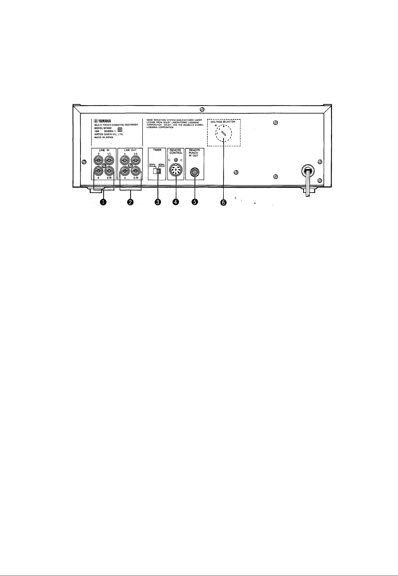
REAR PANEL
1. LINE IN
These are input terminals for rec»rding. For use
of this unit as a 2-channel deck, connect the
terminal 1 to the L-ch terminal and terminal 2 to
the R-ch terminal.
2. LINE OUT
These are output terminals for playback. For
use of this unit as a 2-channel deck, connect
the terminal 1 to the L-ch terminal and terminal
2 to the R-ch terminal.
3. Power source frequency set switch for TIMER
Set this switch to correct frequency according
to your local mains frequency. The switch is
set to 60 Flz when shipping from factory. .
4. REMOTE CONTROL terminal
The use of a RC 10B remote control unit (op
tion) enables you to control the remote tape
driving process.
5. REMOTE PUNCH IN/OUT
The use of a remote control unit FS1 (option)
enables you to control the remote punch'in and
out process.
6. Voltage selector (General Model Only)
Set this to your local AC mains voltage. Failure
to do so will result in seriously impaired
performance or even severe damage.

MULTITRACK TECHNIQUES
BASIC RECORDING
Don't worry about the balance between channels when initially recording the tracks. Instead, pay attention
to setting record level for the best sound quality—minimum distortion and maximum signal-to-noise ratio.
Optimum record level is normally when the program peaks read between 0 and +3 dB on the LED level
indicators. You can set up the ideal overall balance when mixing your 4-track master tape down to stereo
on a standard stereo deck.
INPUT
Mixer
LEVEL
o
o
o
o
MT44D
CH-1
CH-2
CH-3
CH-4
Mixer
LEVEL PAN
o O
o A
o O
o O
L K
L R
Stereo Tape
' • ■
■ • '
OVERDUBBING
With the MT44D it is possible to build up an entire
musical arrangement, part by part, playing each
instrument by yourself.
This is possible because the MT44D lets you monitor
already-recorded tracks while recording new tracks
—in perfect synchronization.
Example:
Record the drums on channel 1, guitar on channel 2,
and synthesizer on channel 3.
Synchro-Track Recording
PING-PONG RECORDING
If you want to record more than 4 parts, one at a time, you'll need to know about "ping-pong" recording.
With this technique you record on tracks 1,2 and 3, and then record these three tracks onto track 4 so
tracks 1, 2 and 3 are opened up for further recording. With some resourceful ping-ponging, you should
be able to record up to 10 independent tracks as shown in the accompanying example.
A RM602 6iN/20UT mixer and RB 35B RACK and PATCHBAY can make ping-pong recording and other
advanced multitrack techniques easy.
Example:
Recording tracks "A" through "J" using the ping-pong process.
©Record parts A, B and C.
CHI A
CH2
CH3
CH4 ——.
................
) Record H.
©Ping-Pong A, B and C to
track 4 while adding part D.
I::;;; a'b'c'+d:::;::
) Move H to track
2 while adding I.
We.f
• A!è'‘ó'+ii);:;:::
xa?b!c‘Td^
) Record parts E and F.
A,B,c -t-.P;;;:::
@ Record J, the last part.
•:-:e.f -i-g:v
:i a,b',c+'d::
©Ping-Pong E and F to track
3 while adding G.
;:;E,F -i-g;:
A,B,c -hd:;
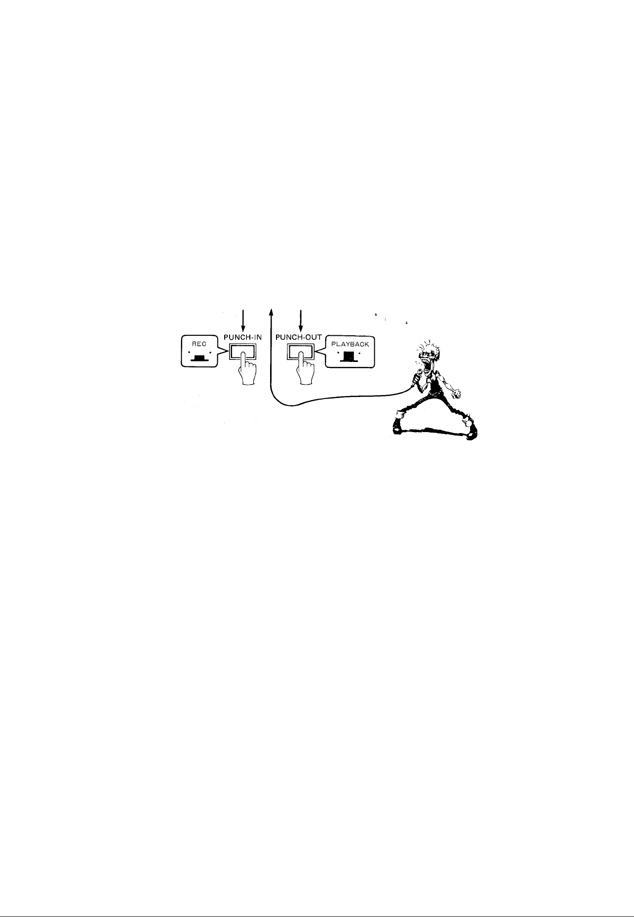
PUNCH-IN/PUNCH-OUT RECORDING
This handy technique makes it possible to redo a section of a track without having to re-record the entire
track. Start playback from a point on the track somewhat before the section to be redone, then, at an
appropriate "break" in the sound, engage the REC mode for that track and start playing. This is the
PUNCH-IN operation. Disengage REC at the end of the required section—PUNCH-OUT—and the job
is done.
This technique requires precision timing on the part of the player and recording engineer—often the same
person-—but the ability to correct mistakes like this can save lots of time and effort.
Modification •
The use of a remote control foot switch FS-1 (option) enables MT44D to control the punch in and out
process by footwork without operating the REC button; the REC button must previouly be pressed in
for a track to be modified before using this function.
The techniques presented in this manual are by no means the only way to record with the MT44D, so use
your imagination and develop your own techniques. With a little resourcefulness and creativity the MT44D
will enable you to create high-quality multitrack master tapes to test out musical ideas, show off your
talents or simply hone your recording skills.
SENSOR SEALS/HANDLING CASSETTE TAPES
USING THE SUPPLIED SENSOR SEALS
The MT44D automatically switches to the 2-channel
mode (regular stereo cassette) or 4-track mode
according to whether a sensor seal is detected on the
loaded cassette. Note that only one side of the tape
can be used in the 4-track mode.
For regular 2-channel operation load a cassette with
out the sensor seal.
For 4-track operation affix one of the three types
of seals provided to the cassette window. Match
the size of the seal to the cassette window. The seal
must fit the cassette window properly or the MT44D
may "misread" the seal and switch to the wrong
mode. If one of the provided seal sizes does not fit,
use a seal that is larger than the cassette window and
trim it to size.
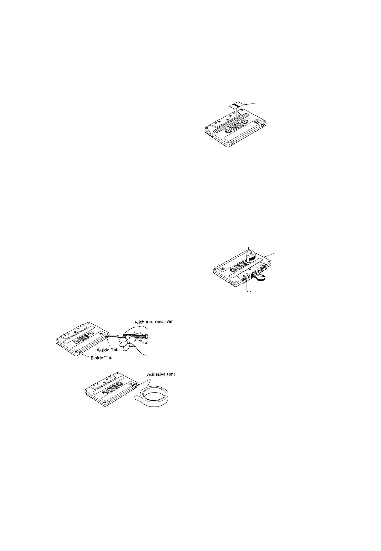
PROTECTING YOUR RECORDINGS
All cassettes have record protection tabs along the
top edge of the cassette shell. If this tape is broken
out using a screwdriver or any other appropriate
implement, recording will be inhibited on the cor
responding side of the tape, thereby protecting your
recordings from accidental erasure. To record on a
tape that has already had its tab removed, simply fix
a piece of adhesive tape over the hole left by the
tab.
Break out both the side "A" and "B"tabs to protect
4-track tapes.
Break off the tab
CORRECTING EXCESSIVE TAPE SLACK
If the cassette tape is slack or is extending from the
cassette housing, there is a risk that it may become
tangled around the capstan or pinch roller—causing
irreparable damage to the tape, and possibly damaging
the transport mechanism. In order to take up this
slack, insert a pencil or bail-point pen into the center
of the reel and rotate to wind the excess tape back
onto the reel.
CASSETTE STORAGE
To prevent slackening of tape, fit a stopper or keep
cassettes in a case (normally supplied with the
cassette). Do not store cassettes in locations with
direct sunlight, high humidity, high temperatures or
magnetic fields (e.g. near television sets, speakers, etc).
Sensor Seals
*The seal should be afl-
fixed to the "B" side of
the cassette for 4-track
recording on side "A".
Cassette Half
NOTE:
The MT44D has been specifically designed to provide
optimum sound quality with chrome (Cr02> formu
lation tape (High Bias, 70/isec. EQ). Do not use
ferrichrome type tapes.
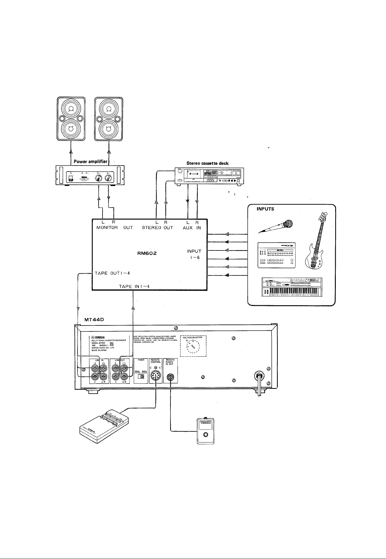
CONNECTION DIAGRAM
Monitor speakers
Remote control
(RC10)
Foot switch
(FS-1)
ш
I—
о
о
7s
а
>
Q
и
>
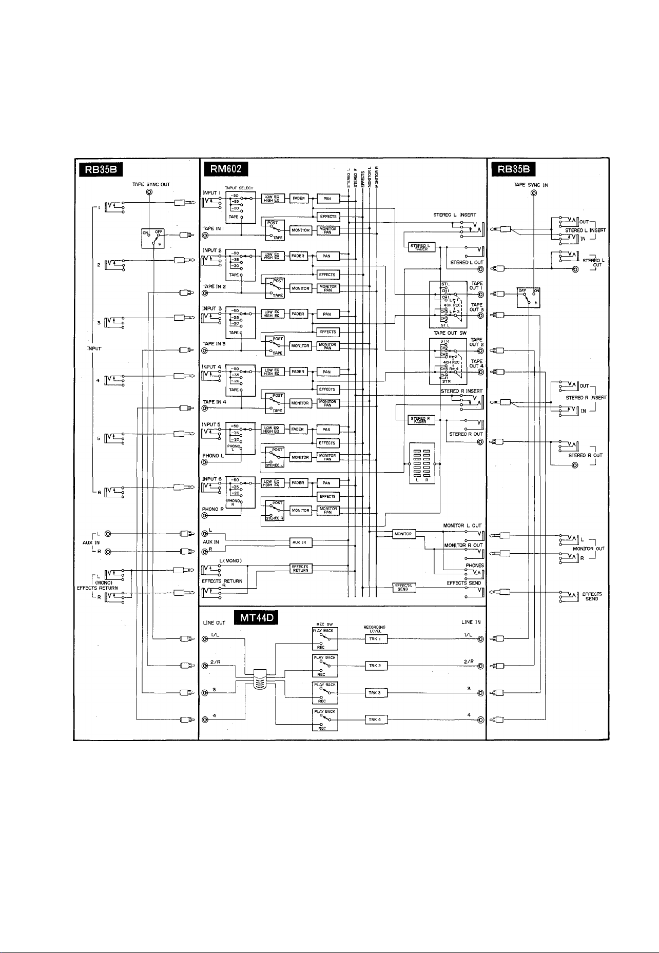
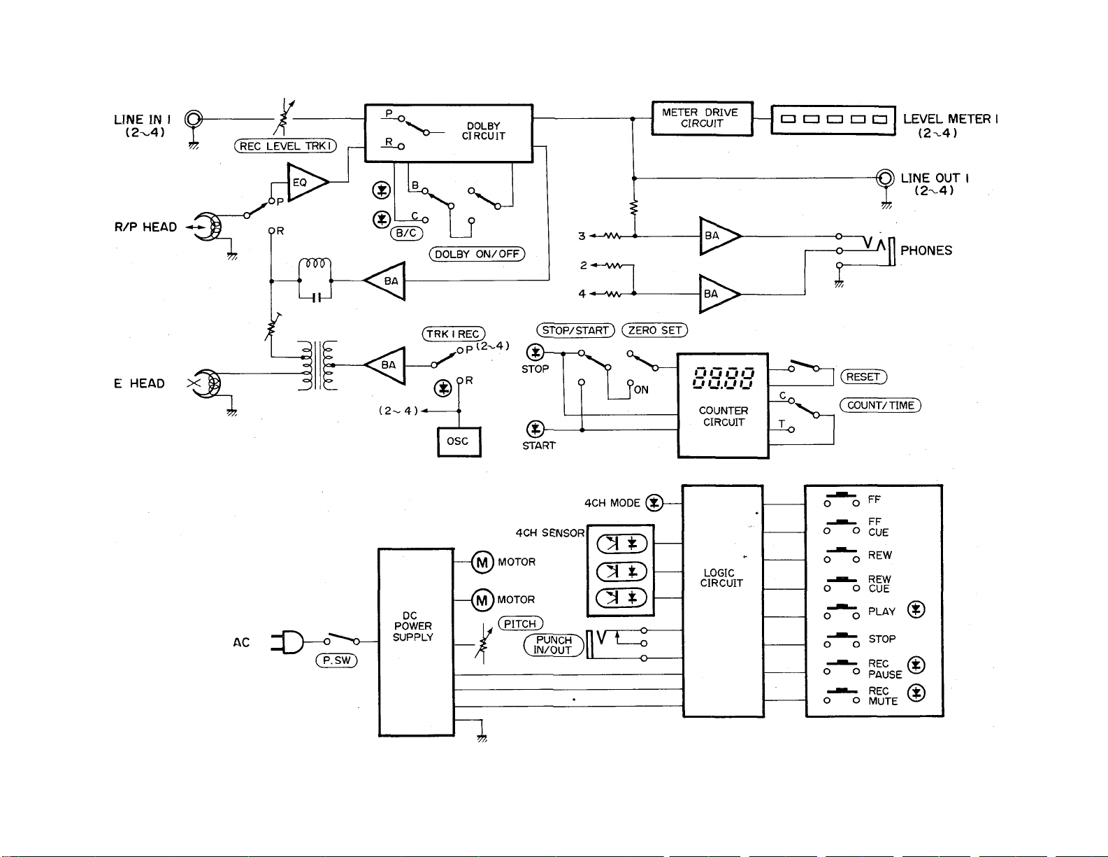
MULTITRACK RECORDING SYSTEM ■ BLOCK DIAGRAM
11

SPECIFICATIONS
Track Configuration
Motor............................................................................................DC motor x 2
Head System
4 channel rec/play ..................................................................Hard Permalloy
4 channel erase......................................................................Ferrite
F. Fwd/Rew Time
Wow and Flutter (WRMS) ...........................................................0.06%
Pitch Control . .■..........................................................................+/—10%
Tape Speed.................................................................................4.75 cm/sec.
Cassette Requirements .........................................
Ree System.................................................................................AC Bias System
Erase System
Frequency Response
Input Sensitivity/Impedance
Output Level/Impedance..............................................................— 10 dB/2.5k-ohms
Sighal-to-Noise Ratio (EIAJ)
(Dolby OFF)............................................................................55 dB
(Dolby BON)
(Dolby CON)
Total Distortion.............................................................................less than 1.0%
Channel Separation.....................................................................better than 50 dB (1kHz)
Power Supply
US & Canadian Model
General model .
Dimensions..................................................................................340 x 322 x 112 mm
Weight........................................................................................4.2 kg (9.3 lb)
Accessories
Options ........................................................................................FS-1 (Foot switch)
*Specifications subject to change without notice.
**TM Dolby laboratories Licensing Corp.
***0dB = 0.775V
.....................................................................
.................... ...............................................
....................
..............................................................................
..................................................................
........................................................
........................................................................
........................................................................
.............................
...
..................................................................110/120/220/240V 50/60Hz
................................... . . . ■
..............................
....................................
4 track, 2 channel 1/4 channel
100 sec.
C-30 to C-90; high bias 70/is EQ
(Type II tape)
(Bias Frequency 85 kHz)
AC System
40 Hz to 14 kHt (+0, —3 dB)
—10 dB/50k-ohms
63 dB
67 dB
120V 60Hz
(13.4 X 12.7 X 4.4 inch)
Connection cord x 2
RC-10 (Remote control)
12
Loading...