

Yamaha FZS600 User Manual

OWNER’S MANUAL
FZS600
FZS600SP
5DM-28199-E3
EAU00001
INTRODUCTION
Welcome to the Yamaha world of motorcycling!
As the owner of a FZS600/FZS600SP, you are benefiting from Yamaha’s vast experi-
ence in and newest technology for the design and the manufacture of high-quality
products, which have earned Yamaha a reputation for dependability.
Please take the time to read this manual thoroughly, so as to enjoy all your FZS600/
FZS600SP’s advantages. The owner’s manual does not only instruct you in how to
operate, inspect and maintain your motorcycle, but also in how to safeguard yourself
and others from trouble and injury.
In addition, the many tips given in this manual will help to keep your motorcycle in
the best possible condition. If you have any further questions, do not hesitate to contact your Yamaha dealer.
The Yamaha team wishes you many safe and pleasant rides. So, remember to put
safety first!
IMPORTANT MANUAL INFORMATION
Particularly important information is distinguished in this manual by the following notations:
The Safety Alert Symbol means ATTENTION! BECOME ALERT! YOU R SAFETY IS INVOLVED!
EAU00005
WARNING
CAUTION:
NOTE:
Failure to follow WARNING instructions could result in severe injury or death to the
motorcycle operator, a bystander or a person inspecting or repairing the motorcycle.
A CAUTION indicates special precautions that must be taken to avoid damage to the
motorcycle.
A NOTE provides key information to make procedures easier or clearer.
NOTE:
@
This manual should be considered a permanent part of this motorcycle and should remain
●
with it even if the motorcycle is subsequently sold.
Yamaha continually seeks advancements in product design and quality. Therefore, while
●
this manual contains the most current product information available at the time of printing,
there may be minor discrepancies between your motorcycle and this manual. If there is any
question concerning this manual, please consult your Yamaha dealer.
@
IMPORTANT MANUAL INFORMATION
EW000002
WARNING
@
PLEASE READ THIS MANUAL CAREFULLY AND COMPLETELY BEFORE OPERATING
THIS MOTORCYCLE.
@
IMPORTANT MANUAL INFORMATION
FZS600/FZS600SP
OWNER’S MANUAL
© 1999 by Yamaha Motor Co., Ltd.
1st Edition, September 1999
All rights reserved. Any reprinting or
unauthorized use without the written
permission of Yamaha Motor Co., Ltd.
is expressly prohibited.
Printed in Japan.
EAU00008
EAU00009
TABLE OF CONTENTS
1 GIVE SAFETY THE RIGHT OF WAY
2 DESCRIPTION
3 INSTRUMENT AND CONTROL FUNCTIONS
4 PRE-OPERATION CHECKS
5 OPERATION AND IMPORTANT RIDING POINTS
6 PERIODIC MAINTENANCE AND MINOR REPAIR
7 MOTORCYCLE CARE AND STORAGE
8 SPECIFICATIONS
9 CONSUMER INFORMATION
INDEX
1
2
3
4
5
6
7
8
9

GIVE SAFETY THE RIGHT OF WAY
GIVE SAFETY THE RIGHT OF WAY...................... .... ....................... 1-1
1
1-
GIVE SAFETY THE RIGHT OF WAY
EAU00021
Motorcycles are fascinating vehicles, which can give you an unsurpassed feeling of power and
freedom. However, they also impose certain limits, which you must accept; even the best motorcycle
does not ignore the laws of physics.
1
Regular care and maintenance are essential for preserving your motorcycle’s value and operating
condition. Moreover, what is true for the motorcycle is also true for the rider: good performance
depends on being in good shape. Riding under the influence of medication, drugs and alcohol is, of
course, out of the question. Motorcycle ri der s - m ore t han car drive rs - mu st alwa ys b e at t he ir m ent al
and physical best. Under the influence of even small amounts of alcohol, there is a tendency to take
dangerous risks.
Protective clothing is as essential for the motorcycle rider as seat belts are for car drivers and
passengers. Always wear a complete motorcycle suit (whether made of leather or tear-resistant
synthetic materials with protectors), sturdy boots, motorcycle gloves and a properly fitting helmet.
Optimum protective wear, however, should not encourage carelessness. Though full-coverage
helmets and suits, in particular, create an illusion of total safety and protection, motorcyclists will
always be vulnerable. Riders who lack critical self-control run the risk of going too fast and are apt to
take chances. This is even more dangerous in wet weather. The good motorcyclist rides safely,
predictably and defensively - avoiding all dangers, including those caused by others.
Enjoy your ride!
Give safety the right of way
1-1
DESCRIPTION
Left view............................................................................................. 2-1
Right view...........................................................................................2-2
Controls/Instruments.......................................................................... 2-3
2
2-
DESCRIPTION
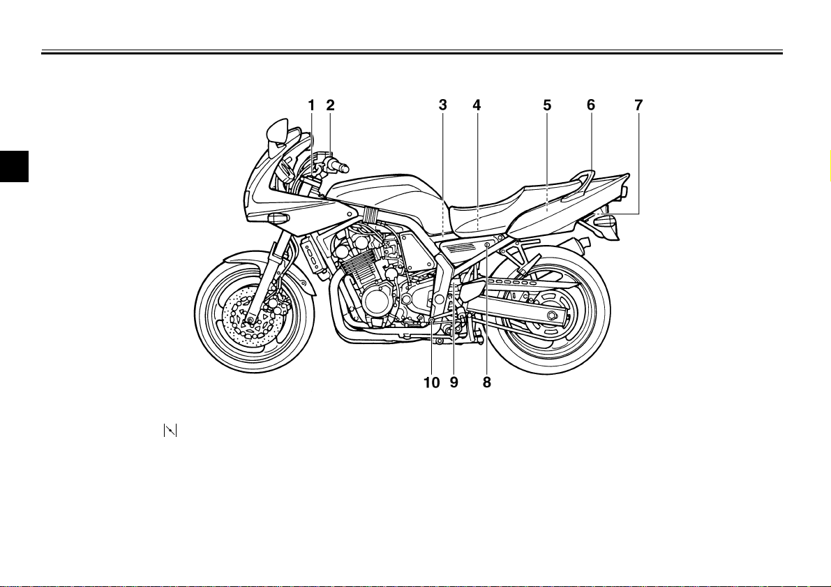
Left view
2
EAU00026
1.Front fork spring preload adjusting bolt (page 3-16)
2.Starter (choke) “ ” (page 3-14)
3.Air filter (page 6-15)
4.Fuses (page 6-33)
5.Storage compartment (page 3-15)
6.Grab bar
7.Luggage strap holder (page 3-17)
8.Seat lock (page 3-14)
9.Rear shock absorber spring preload
adjusting ring (page 3-17)
10.Shift pedal (page 3-11)
2-1
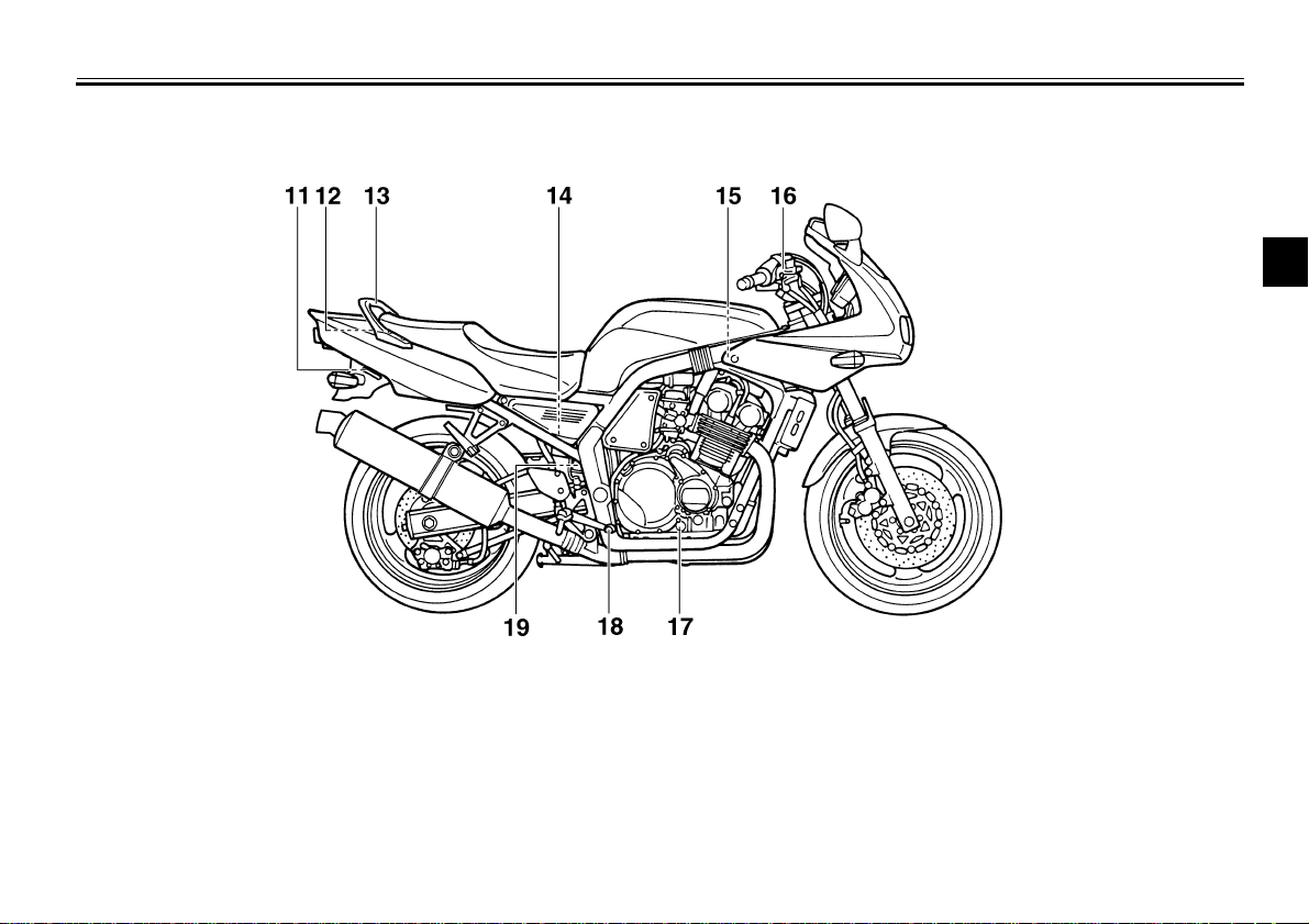
Right view
DESCRIPTION
2
11.Luggage strap holder (page 3-17)
12.Tool kit (page 6-1)
13.Grab bar
14.Rear brake fluid master cylinder (page 6-26)
15.Radiator cap (page 6-14)
16.Front brake fluid master cylinder (page 6-25)
17.Oil level check window (page 6-9)
18.Rear brake pedal (page 3-11)
19.Coolant reservoir cap (page 6-13)
2-2
DESCRIPTION
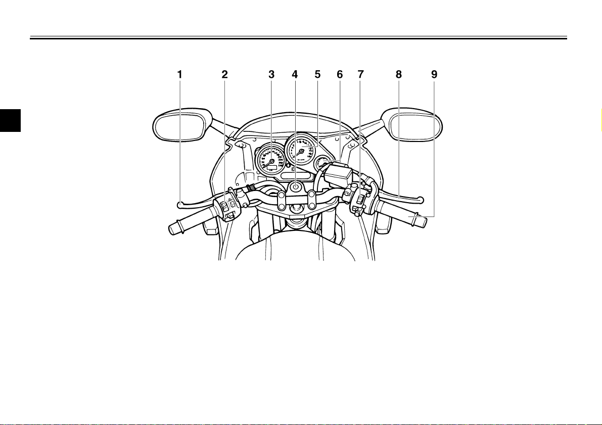
Controls/Instruments
2
1.Clutch lever (page 3-10)
2.Left handlebar switches (page 3-9)
3.Speedometer (page 3-6)
4.Main switch (page 3-1)
5.Tachometer (page 3 -7)
6.Fuel gauge (page 3-8)
7.Right handlebar switches (page 3-10)
8.Front brake lever (page 3-11)
9.Throttle grip (page 6-19)
2-3
INSTRUMENT AND CONTROL FUNCTIONS
Main switch/Steering lock .....................................3-1
Indicator lights ......................................................3-3
Oil level indicator circuit check..............................3-4
Fuel indicator circuit check ...................................3-5
Speedometer........................................................3-6
Tachometer...........................................................3-7
Diagnosis device...................................................3-7
Antitheft alarm (optional) ......................................3-8
Fuel gauge............................................................3-8
Handlebar switches .............. ... .... ... ... ... .... ............3-9
Clutch lever.........................................................3-10
Shift pedal...........................................................3-11
Front brak e lever.................................................3-11
Rear brake pedal................................................ 3-11
Fuel tank cap ..................................................... 3-12
Fuel.................................................................... 3-13
Fuel tank breather hose..................................... 3-13
Starter (choke) “ ”........................................... 3-14
Seat.................................................................... 3-14
Helmet holder..................................................... 3-15
Storage compartment ........................ ................ 3- 1 5
Front fork adjustment ......................................... 3-16
Rear shock absorber adjustment ....................... 3-17
Luggage strap holders .................... ... ................ 3-17
Sidestand.................... .... ................................... 3-18
Sidestand/clutch switch operation check............ 3-1 9
3
3-
WARNING
INSTRUMENT AND CONTROL FUNCTIONS
3
EAU00027
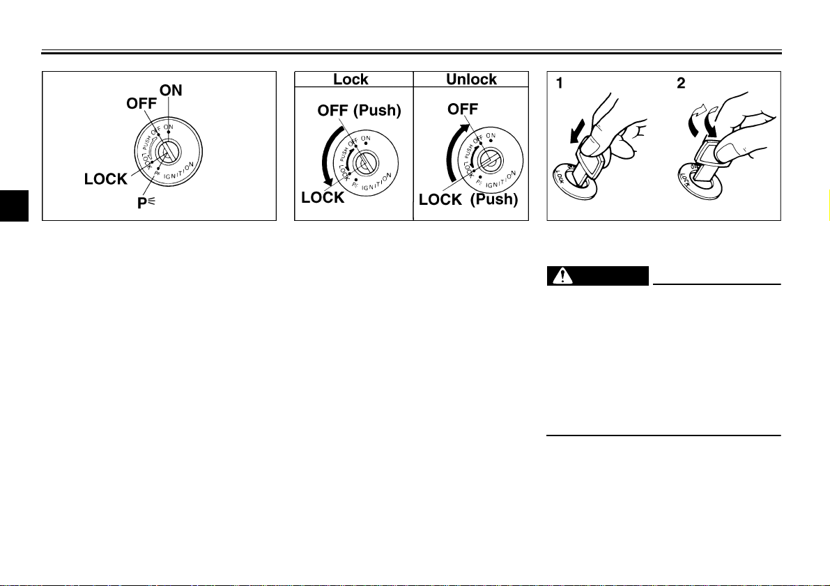
Main switch/Steering lock
The main switch controls the ignition
and lighting systems. Its operation is
described below.
ON
Electrical circuits are switched on. The
engine can be started. The key cannot
be removed in this position.
OFF
All electrical circuits are switched off.
The key can be removed in this position.
EAU00029
EAU00036
EAU00038
EAU00040
LOCK
The steering is locked in this position
and all electrical circuits are switched
off. The key can be removed in this position. To lock the steering, turn the
handlebars all the way to the left. While
pushing the key into the main switch,
turn it from “OFF” to “LOCK” and remove it. To release the lock, turn the
key to “OFF” while pushing.
3-1
1. Push
2. Turn
EW000016
@
Never turn the key to “OFF” or
“LOCK” when the motorcycle is
moving. The electrical circuits will
be switched off which may result in
loss of control or an accident. Be
sure the motorcycle is stopped before turning the key to “OFF” or
“LOCK”.
@
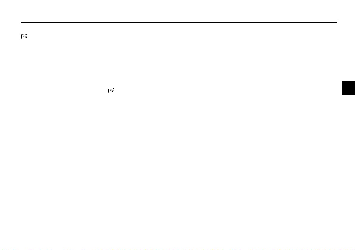
EAU03013
(Parking)
The steering is locked in this position,
and the taillights and auxiliary light
come on but all other circuits are off.
The key can be removed in this position.
To use the parking position, first lock
the steering, then turn the key to “ ”.
Do not use this position for an extended length of time as the battery may
discharge.
INSTRUMENT AND CONTROL FUNCTIONS
3
3-2
INSTRUMENT AND CONTROL FUNCTIONS
CAUTION:
3
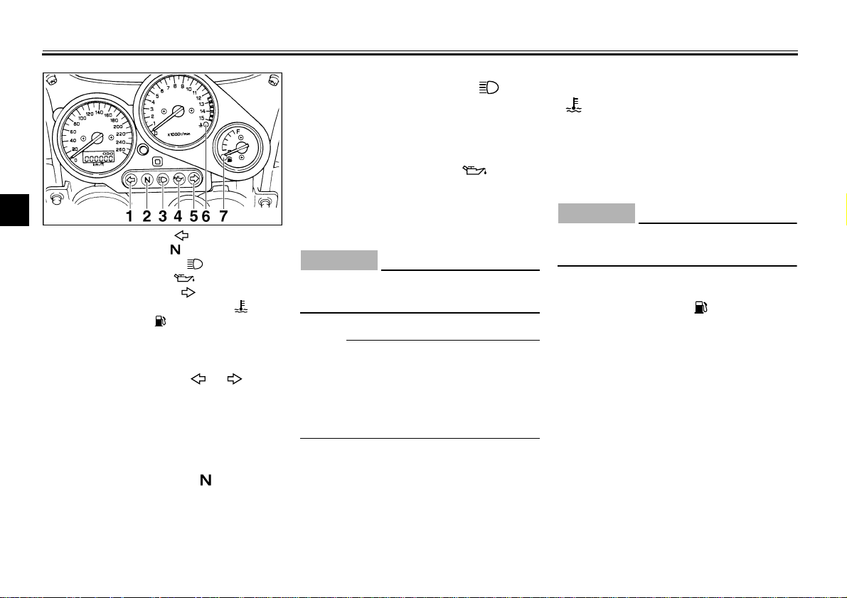
1. Left turn indicator light “ ”
2. Neutral indicator light “ ”
3. High beam indicator light “ ”
4. Oil level indicator light “ ”
5. Right turn indicator light “ ”
6. Coolant temperature indicator light “ ”
7. Fuel indicator light “ ”
Indicator lights
Turn indicator lights “ ” “ ”
The corresponding indicator flashes
when the turn switch is moved to the
left or right.
Neutral indicator light “ ”
This indicator comes on when the
transmission is in neutral.
EAU00056
EAU00058
EAU00061
EAU00063
High beam indicator light “ ”
This indicator comes on when the
headlight high beam is used.
EAU01313
Oil level indicator light “ ”
This indicator comes on when the oil
level is low. This light circuit can be
checked by the procedure on page 3-4.
EC000000
CAUTION:
@
Do not run the motorcycle until you
know it has sufficient engine oil.
@
NOTE:
@
Even if the oil is filled to the specified
level, the indicator light may flicker
when riding on a slope or during sudden acceleration or deceleration, but
this is normal.
@
EAU01716
Coolant temperature indicator light
“”
This indicator light comes on when the
engine overheats. If the light comes on,
stop the engine immediately and allow
the engine to cool.
EC000002
@
When the engine is overheated, do
not continue riding.
@
EAU01154
Fuel indicator light “ ”
When the fuel level drops below approximately 3.5 L, this light will come
on. When this light comes on, fill the
tank at the first opportunity. This light
circuit can be checked by the procedure on page 3-5.
3-3
CB-48E
INSTRUMENT AND CONTROL FUNCTIONS
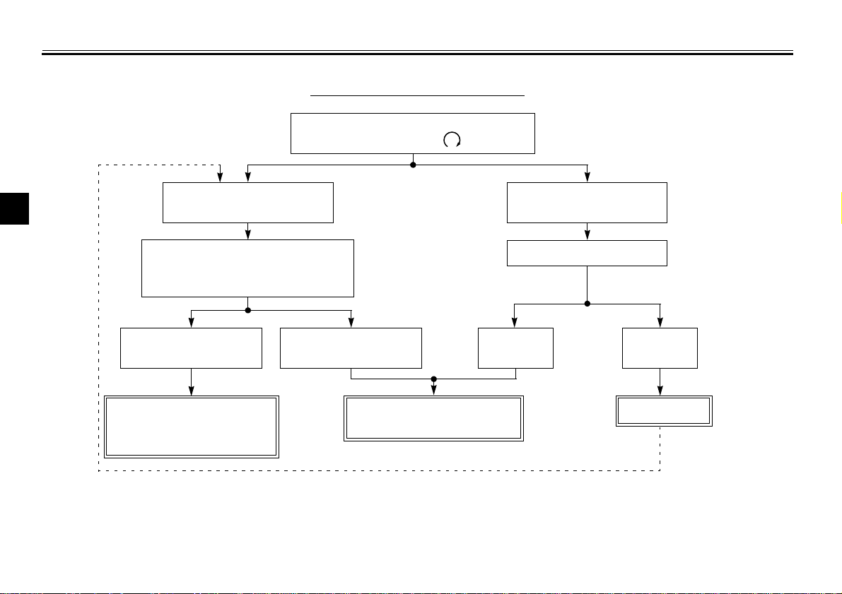
EAU00071
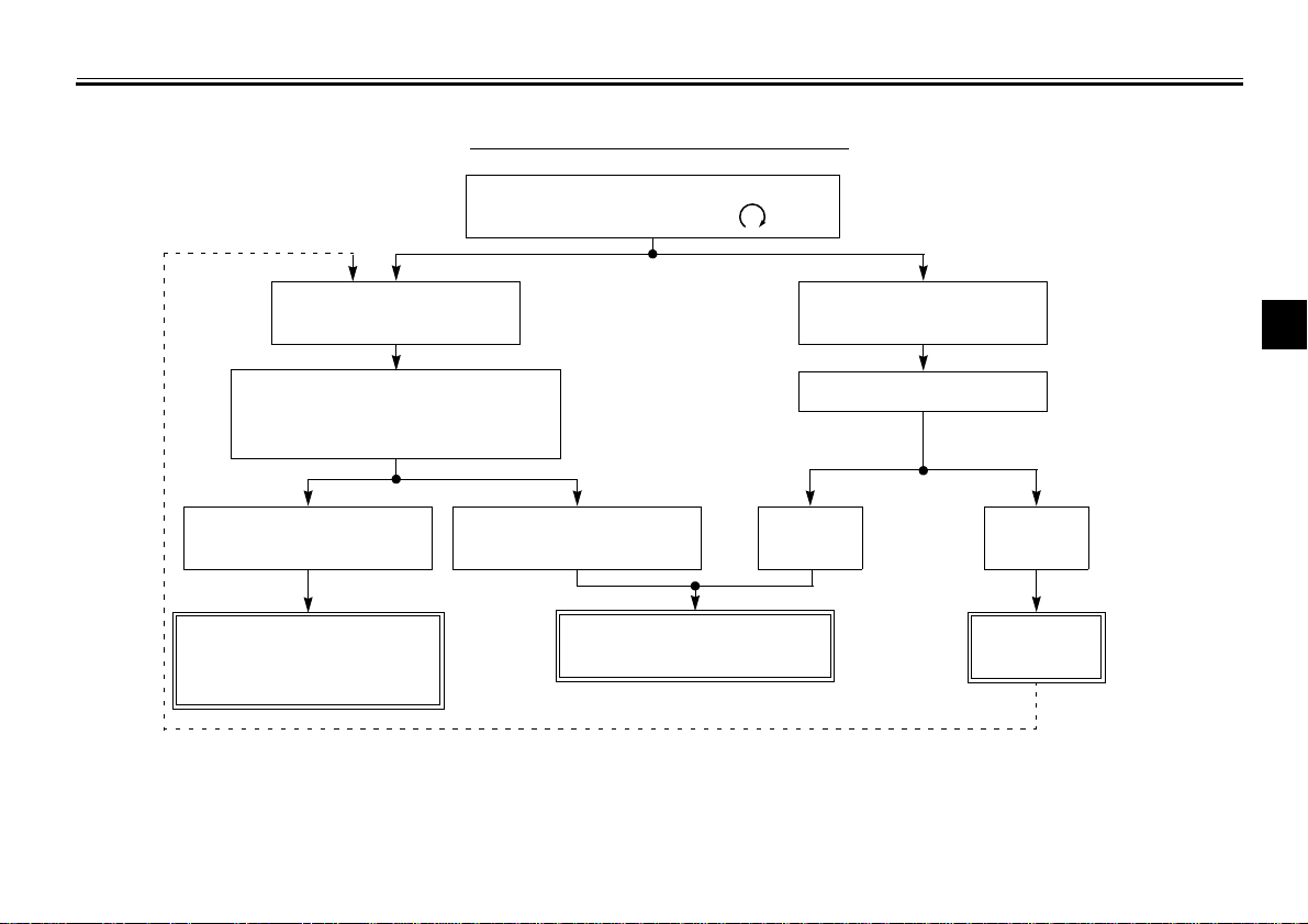
Oil level indicator circuit check
Turn the main switch to “ON” and
the engine stop switch to “ ”.
Oil level indicator light
does not come on.
Put the transmission in neutral or
apply the clutch lever, then push
the start switch.
Oil level indicator light
comes on.
Engine oil level and
electrical circuit are OK.
Go ahead with riding.
Oil level indicator light
does not come on.
Ask a Yamaha dealer to
inspect electrical circuit.
3-4
Oil level indicator light
comes on.
Check engine oil level.
Oil level
is OK.
3
Oil level
is low.
Supply
engine oil.
INSTRUMENT AND CONTROL FUNCTIONS
Fuel indicator circuit check
CB-46E
Turn the main switch to “ON” and the
engine stop switch to “ ”.
EAU00085
Fuel indicator light does
3
not come on.
Put the transmission in neutral or
Fuel indicator light
comes on.
Check the fuel level.
apply the clutch lever, then push
the start switch.
Fuel indicator light
comes on.
Fuel level and electrical
circuit are OK.
Fuel indicator light
does not come on.
Ask a Yamaha dealer to
inspect electrical circuit.
Fuel level
is OK.
Fuel level
is low.
Supply fuel.
Go ahead with riding.
3-5
INSTRUMENT AND CONTROL FUNCTIONS
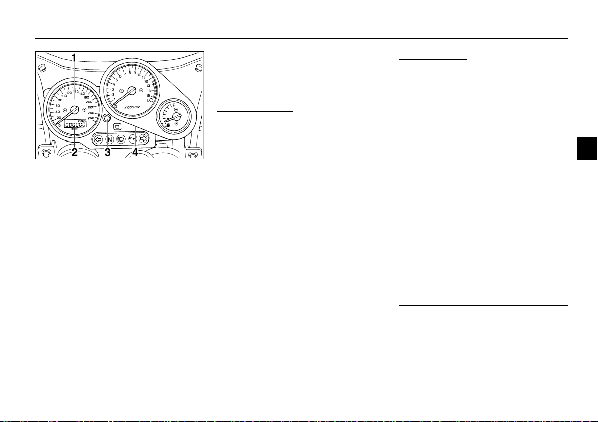
NOTE:
1. Speedometer
2. Odometer/Tripmeter/Clock
3. “SELECT” button
4. “RESET” button
EAU03028*
Speedometer
This speedometer is equipped with:
an odometer
●
two tripmeters
●
a clock
●
Odometer and tripmeter modes
When set to “ODO”, the motorcycle’s
total mileage is indicated.
When set to “TRIP 1” or “TRIP 2”, the
motorcycle’s mileage since the tripmeter was last reset is indicated. Use the
tripmeters to estimate how far you can
ride on a tank of fuel. This information
will enable you to plan fuel stops in the
future.
Selecting a mode
Push the “SELECT” button to change
between the odometer mode “ODO” ,
the tripmeter modes “TRIP 1” and
“TRIP 2”, and the clock mode in the following order:
“ODO” → “TRIP 1” → “TRIP 2”
→
Clock → “ODO”
Resetting a meter
To reset either tripmeter 1 or 2 to 0.0,
select either by pushing the “SELECT”
button and push the “RESET” button
for at least one second.
Clock mode
To change the display to the clock
mode, push the “SELECT” button.
To change the display back to the
odometer mode, push the “SELECT”
button.
To set the clock
1. Push both the “SELECT” and
“RESET” buttons for at least two
seconds.
2. When the hour digits start flashing,
push the “RESET” button to set
the hours.
3. Push the “SELECT” button to
change the minutes.
4. When the minute digits start flashing, push the “RESET” button to
set the minutes.
5. Push the “SELECT” button to start
the clock.
@
After setting the clock, be sure to push
the “SELECT” button before turning the
main switch to “OFF”, otherwise the
clock will not be set.
@
3
3-6
INSTRUMENT AND CONTROL FUNCTIONS
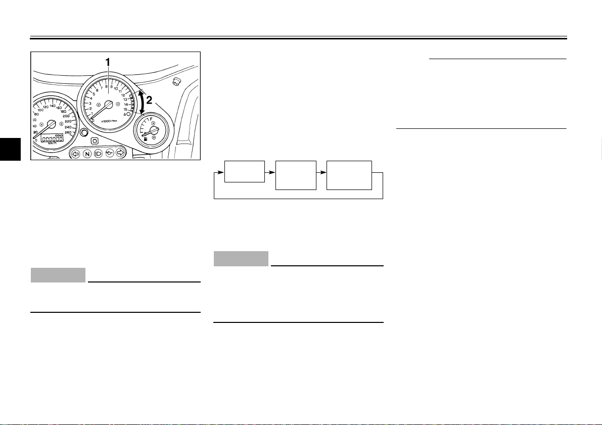
NOTE:
3
1. Tachometer
2. Red zone
Tachometer
This model is equipped with an electric
tachometer so the rider can monitor the
engine speed and keep it within the
ideal power range.
CAUTION:
@
Do not operate in the red zone.
Red zone: 12,500 r/min and above
@
EAU00101
EC000003
EAU01322*
Diagnosis device
This model is equipped with a diagnosis device for the Throttle Position Sensor (T.P.S.) circuit.
If some trouble should occur in the circuit, the tachometer will repeatedly display as follows:
CB-70E
0 r/min for
3 seconds.
3,000 r/min
for 2.5 seconds.
If the tachometer displays as described
above, take your motorcycle to a
Yamaha dealer for repair.
CAUTION:
@
To prevent engine damage, be sure
to consult a Yamaha dealer as soon
as possible if the tachometer displays a repeated change in r/min.
@
Current engine r/min for
3 seconds.
EC000004
@
If the tachometer should display 4,000
instead of 3,000 r/min, the speed sensor may be disconnected or short-circuited. In this case, ask a Yamaha
dealer to inspect the motorcycle.
@
3-7
EAU00109
Antitheft alarm (optional)
An antitheft alarm can be equipped to
this motorcycle. Consult your Yamaha
dealer to obtain and install the alarm.
INSTRUMENT AND CONTROL FUNCTIONS
3
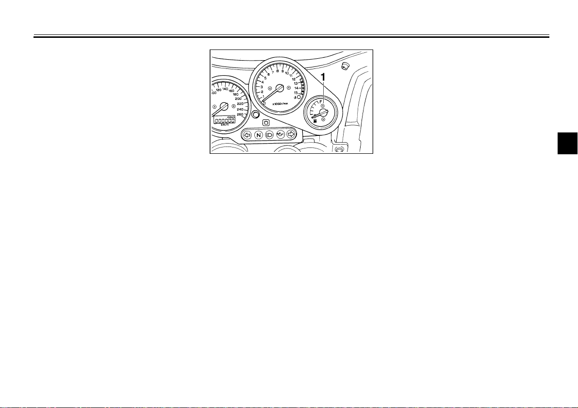
1. Fuel gauge
EAU00110
Fuel gauge
This model is equipped with an electric
fuel gauge so the rider can monitor the
fuel level in the fuel tank. When the
needle indicates “E” (Empty), about
3.5 L remain in the fuel tank.
3-8
INSTRUMENT AND CONTROL FUNCTIONS
NOTE:
3
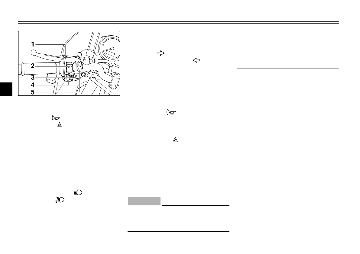
1. Pass switch “PASS”
2. Dimmer switch
3. Turn signal switch
4. Horn switch “ ”
5. Hazard switch “ ”
Handlebar switches
Pass switch “PASS”
Press the switch to operate the passing
light.
Dimmer switch
Turn the switch to “ ” for the high
beam and to “ ” for the low beam.
EAU00118
EAU00120
EAU00121
EAU00127
Turn signal switch
To signal a right-hand turn, push the
switch to “ ”. To signal a left-hand
turn, push the switch to “ ”. Once the
switch is released it will return to the
center position. To cancel the signal,
push the switch in after it has returned
to the center position.
EAU00129
Horn switch “ ”
Press the switch to sound the horn.
EAU00144
Hazard switch “ ”
The hazard switch should be turned on
under emergency or hazardous conditions. All turn signal lights will flash simultaneously when this switch is
turned on with the main switch in the
“ON” or “P” position.
EC000006
CAUTION:
@
The battery can discharge from extended use, making it difficult to operate the starter.
@
@
Turn on the hazard switch to warn other drivers if your motorcycle must be
stopped where it might be a traffic hazard.
@
3-9
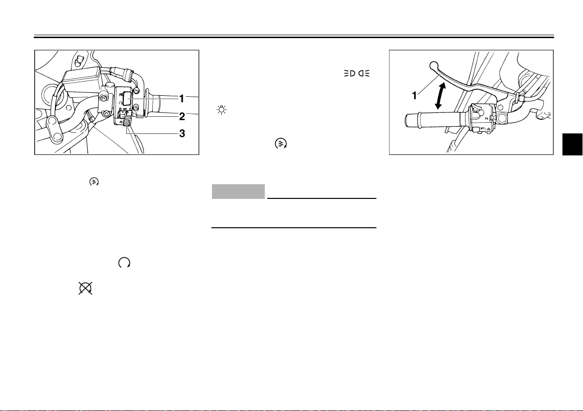
1. Engine stop switch
2. Lights switch
3. Start switch “ ”
EAU00138
Engine stop switch
The engine stop switch is a safety device for use in an emergency such as
when the motorcycle overturns or if
trouble occurs in the throttle system.
Turn the switch to “ ” to start the engine. In case of emergency, turn the
switch to “ ” to stop the engine.
INSTRUMENT AND CONTROL FUNCTIONS
EAU00134
Lights switch
Turning the light switch to “ ”,
turns on the auxiliary light, meter lights
and taillight. Turning the light switch to
“ ” turns the headlight on also.
EAU00143
Start switch “ ”
The starter motor cranks the engine
when pushing the start switch.
EC000005
CAUTION:
@
See starting instructions prior to
starting the engine.
@
1. Clutch lever
Clutch lever
The clutch lever is located on the left
handlebar, and the ignition circuit cutoff system is incorporated in the clutch
lever holder. Pull the clutch lever to the
handlebar to disengage the clutch, and
release the lever to engage the clutch.
The lever should be pulled rapidly and
released slowly for smooth clutch operation. (Refer to the engine starting procedures for a description of the ignition
circuit cut-off system.)
3
EAU00152
3-10
INSTRUMENT AND CONTROL FUNCTIONS
3
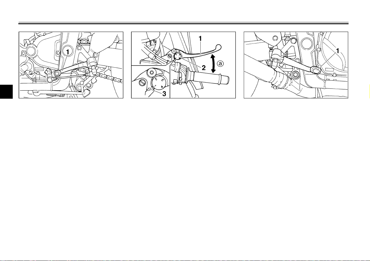
1. Shift pedal 1. Front brake lever
Shift pedal
This motorcycle is equipped with a constant-mesh 6-speed transmission.
The shift pedal is located on the left
side of the engine and is used in combination with the clutch when shifting.
EAU00157
2. Lever position adjuster
3. Arrow mark
a. Lever distance
Front brake lever
The front brake lever is located on the
right handlebar and is equipped with a
brake lever adjusting dial. To activate
the front brake, pull the lever toward
the handlebar. To adjust the front brake
lever position, turn the brake lever adjusting dial while pulling the lever forward. Make sure the setting on the
brake lever adjusting dial is aligned
with the arrow mark.
3-11
EAU00161
1. Rear brake pedal
EAU00162
Rear brake pedal
The rear brake pedal is on the right
side of the motorcycle. Press down on
the brake pedal to apply the rear brake.
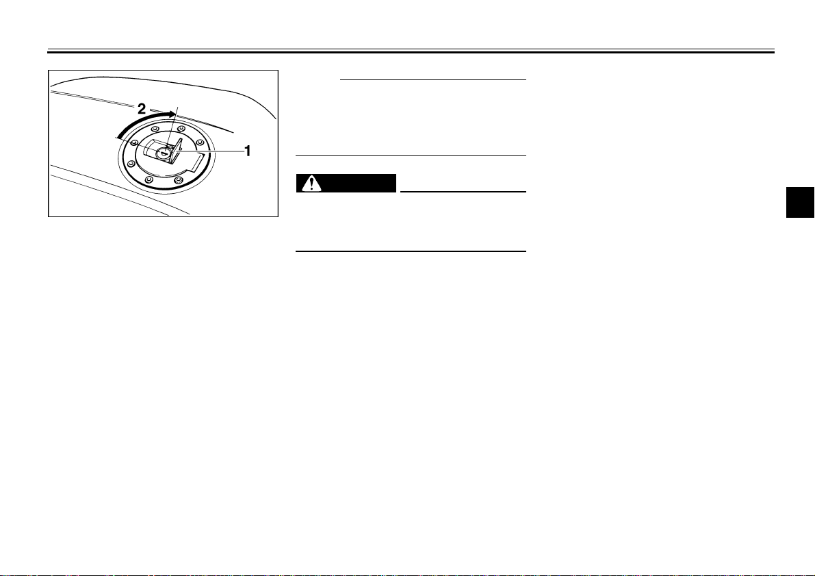
1. Lock cover
2. Open
EAU02935
Fuel tank cap
To open
Open the lock cover. Insert the key and
turn it 1/4 turn clockwise. The lock will
be released and the cap can be
opened.
To close
Push the tank cap into position with the
key inserted. To remove the key, turn it
counterclockwise to the original position. Then, close the lock cover.
INSTRUMENT AND CONTROL FUNCTIONS
NOTE:
@
This tank cap cannot be closed unless
the key is in the lock. The key cannot
be removed if the cap is not locked
properly.
@
WARNING
@
Be sure the cap is properly installed
and locked in place before riding the
motorcycle.
@
EW000023
3
3-12
INSTRUMENT AND CONTROL FUNCTIONS
CAUTION:
@
Always wipe off spilled fuel immediately with a dry and clean soft cloth.
Fuel may deteriorate painted surfaces or plastic parts.
@
3
1. Filler tube
2. Fuel level
EAU01183
Fuel
Make sure there is sufficient fuel in the
tank. Fill the fuel tank to the bottom of
the filler tube as shown in the illustration.
WARNING
@
Do not overfill the fuel tank. Avoid
spilling fuel on the hot engine. Do
not fill the fuel tank above the bottom of the filler tube or it may overflow when the fuel heats up later and
expands.
@
EW000130
Recommended fuel:
Regular unleaded gasoline with a
research octane number of 91 or
higher.
Fuel tank capacity:
Total:
20 L
Reserve:
3.5 L
NOTE:
@
If knocking or pinging occurs, use a different brand of gasoline or higher octane grade.
@
EAU00185
EAU00191
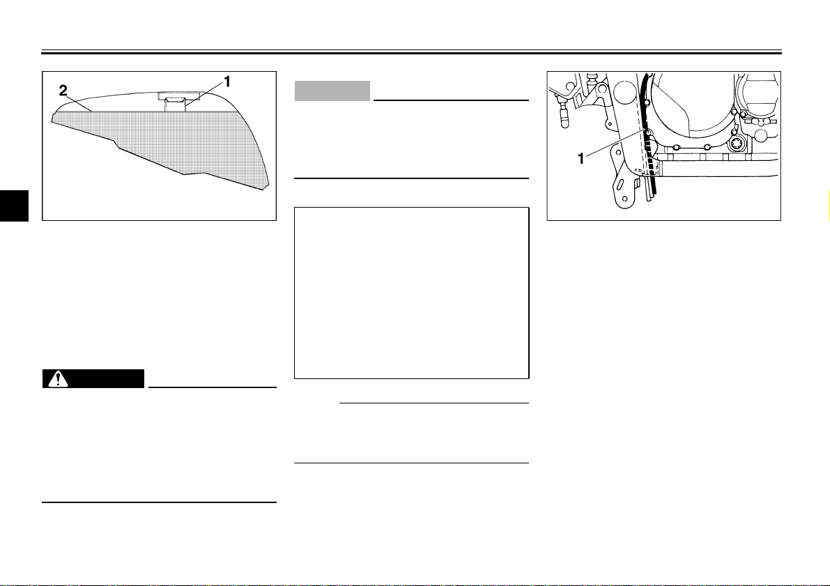
1. Fuel tank breather hose
EAU02955
Fuel tank breather hose
This model is equipped with a fuel tank
breather hose.
Before using this motorcycle:
Check the fuel tank breather hose
●
connection.
Check the fuel tank breather hose
●
for cracks or damage and replace
it if damaged.
Make sure the end of the fuel tank
●
breather hose is not blocked and
clean it if necessary.
3-13
INSTRUMENT AND CONTROL FUNCTIONS
3
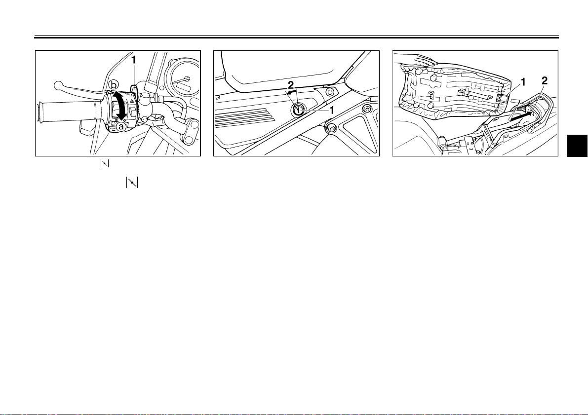
1. Starter (choke) “ ” 1. Seat lock
EAU02976
2. Open
Starter (choke) “ ”
Starting a cold engine requires a richer
air-fuel mixture. A separate starter circuit supplies this mixture.
Move in direction a to turn on the
starter (choke).
Move in direction b to turn off the
starter (choke).
Seat
To remove
Insert the key into the seat lock and
turn it counterclockwise. While holding
the key in that position, lift up the front
of the seat.
3-14
EAU01319
1. Projection
2. Seat holder
To install
Insert the projection on the rear of the
seat into the seat holder, then push
down on the front of the seat.
INSTRUMENT AND CONTROL FUNCTIONS
3
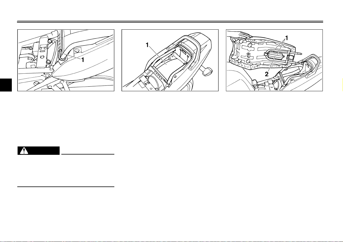
1. Helmet holder 1. Storage compartment 1. U-LOCK
Helmet holder
The helmet holder is under the seat.
Remove the seat and hook the helmet
on the helmet holder. Then, reinstall
the seat and lock it.
WARNING
@
Never ride with a helmet in the helmet holder. The helmet may hit objects, causing loss of control and
possibly an accident.
@
EAU00263
EW000030
EAU01688
Storage compartment
This compartment is designed to store
a genuine Yamaha U-LOCK. (Other
locks may not fit.)
Be sure the lock is fastened securely
with the straps when storing it in the
compartment.
To prevent losing the straps, be sure to
secure them even when a U-LOCK is
not being stored in the compartment.
When storing this Owner’s manual or
other documents in the compartment,
2. Strap
be sure to put them in a vinyl bag so
they do not get wet. When washing the
motorcycle, be careful not to flood this
compartment with water.
3-15
INSTRUMENT AND CONTROL FUNCTIONS
3
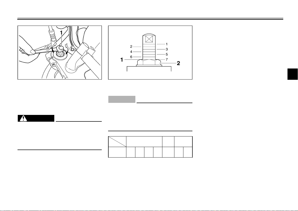
1. Spring preload adjusting bolt 1. Setting position
EAU00285
2. Front fork cap
Front fork adjustment
This front fork is equipped with spring
preload adjusting bolts.
EW000037
WARNING
@
Each fork leg must be set to the
same pressure. Uneven setting can
cause poor handling and loss of stability.
@
Adjust spring preload as follows. Turn
the adjusting bolts in direction a to increase spring preload and in
directionb to decrease spring preload.
CAUTION:
@
The grooves are provided to show
the adjustment level. Always keep
the adjustment level equal on both
fork legs.
@
CI-18E
Adjusting
position
1234 5 67
Hard
3-16
Stan-
dard
EC000013
Soft
 Loading...