


100A
Table of contents
 Loading...
YAMAHA 100A, E115A, 115B, 115C, 115F PARTS CATALOGUE
...
WORLDWIDE
100A, E115A, 115B,
115C, 115F, 130B,
L130B, 140B
USA, CANADA
C115X, 115X,
S115X, B115X,
130X, S130X, L130X
290359
SERVICE MANUAL
MANUEL D’ENTRETIEN
WARTUNGSHANDBUCH
MANUAL DE SERVICIO
6E5-28197-Z9-C1
E
F
D
ES

E
PREFACE
This manual has been prepared by the Yamaha Motor Company, Ltd. primarily for use by
Yamaha dealers and their trained mechanics when performing maintenance procedures and
repairs to Yamaha equipment. It has been written to suit the needs of persons who have a
basic understanding of the mechanical and electrical concepts and procedures inherent in the
work, for without such knowledge attempted repairs or service to the equipment could render
it unsafe or unfit for use.
Because the Yamaha Motor Company, Ltd. has a policy of continuously improving its products, models may differ in detail from the descriptions and illustrations given in this publication. Use only the latest edition of this manual. Authorized Yamaha dealers are notified
periodically of modifications and significant changes in specifications and procedures, and
these are incorporated in successive editions of this manual.
100A, E115A, 115B, 115C, 115F,
130B, L130B, 140B
SERVICE MANUAL
1999 Yamaha Motor Co., Ltd.
1st Edition, March 1999
All rights reserved.
No part of this publication may be
reproduced or transmitted in any form or by
any means including photocopying and
recording without the written permission of
the copyright holder.
Such written permission must also be
obtained before any part of this publication
is stored in a retrieval system of any nature.
Printed in Japan
P/N 6E5-28197-Z9-C1

F D
ES
PREFACE
Ce manuel a été préparé par la Yamaha
Motor Company principalement à
l’intention des concessionnaires
Yamaha et de leurs mécaniciens qualifiés afin de les assister lors de l’entretien
et la réparation des produits Yamaha. Ce
manuel est destiné à des personnes possédant les connaissances de base en
mécanique et en électricité sans lesquelles l’exécution de réparations ou d’entretiens peut rendre les machines impropres
ou dangereuses à l’emploi.
La Yamaha Motor Company, Ltd.
s’efforce en permanence d’améliorer ses
produits. Par conséquent, il se peut que
les modèles diffèrent légèrement des
descriptions et illustrations de ce manuel.
Les modifications et les changements
significatifs dans les caractéristiques ou
les procédés sont notifiés à tous les concessionnaires Yamaha et sont publiés
dans les éditions ultérieures de ce
manuel.
100A, E115A, 115B, 115C, 115F,
130B, L130B, 140B
MANUEL D’ENTRETIEN
1999 Yamaha Motor Co., Ltd.
1ère édition, mars 1999
Tous droits réservés.
Toute reproduction ou transmis-
sion de ce manuel, même partielle,
par quelque procédé que ce soit, y
compris par photocopie ou enregis-
trement, requiert l’accord écrit
préalable de la
Yamaha Motor Co., Ltd.
De même, l’introduction de toute
partie de ce manuel dans un sys-
tème d’archivage requiert cet
accord écrit préalable.
Imprimé au Japon
P/N 6E5-28197-Z9-C1
VORWORT
Dieses Handbuch wurde von der
Yamaha Motor Company, Ltd. vorrangig für Yahama-Vertragshändler und deren qualifizierte
Mechaniker geschrieben, um sie
bei der Durchführung von Wartungs- und Reparaturarbeiten an
Yamaha-Motoren zu unterstützen.
Es werden Grundkenntnisse der
mechanischen und elektrischen
Wirkungsweise und der Arbeitsverfahren vorausgesetzt, denn
ohne diese Grundkenntnisse versuchte Wartungs- und Reparaturarbeiten machen das Produkt eher
unsicher oder sogar gebrauchsunfähig.
Die Yamaha Motor Company, Ltd.
ist stets bestrebt, ihre Produkte
ständig zu verbessern. Einzelne
Modelle können im Detail von den
hier enthaltenen Beschreibungen
und Abbildungen abweichen.
Benutzen Sie immer nur die neueste Ausgabe dieses Handbuchs.
Autorisierte Yamaha-Vertragshändler werden regelmäßig vorab
über Modifikationen und wesentliche Änderungen der technischen
Daten und Verfahren unterrichtet,
die in der jeweils nächsten Ausgaben dieses Handbuchs eingearbeitet werden.
100A, E115A, 115B, 115C, 115F,
130B, L130B, 140B
WARTUNGSHANDBUCH
1999 Yamaha Motor Co., Ltd.
1. Ausgabe, März 1999
Alle Rechte vorbehalten.
Diese Veröffentlichung darf
auch teilweise in keiner Weise
oder durch irgendein Verfah-
ren ohne die schriftlichts
Genehmigung des Urheber-
rechts-Inhabers reproduziert
oder übertragen werden. Dies
gilt auch für Fotokopien und
Aufzeichnungen. Die schriftli-
che Genehmigung ist vor der
Übernahme in irgendein Infor-
mationssystem einzuholen.
Gedruckt in Japan
P/N 6E5-28197-Z9-C1
PREFACIO
Este manual ha sido preparado por
Yamaha Motor Company Ltd. principalmente para que lo empleen los concesionarios Yamaha y sus mecánicos
cualificados al llevar a cabo los procedimientos de mantenimiento y de reparación de los equipos Yamaha. Se ha
escrito para adaptarlo a las necesidades
de las personas que ya tienen un conocimiento básicos de los conceptos mecánicos y eléctricos y de los procedimientos
inherentes al trabajo, porque sin tales
conocimientos las reparaciones o el servicio del equipo podría dejar el equipo
inseguro o inadecuado para la utilización.
Puesto que Yamaha Motor Company,
Ltd. sigue una política de mejora continua de sus productos, los modelos pueden diferir en detalles de las
descripciones e ilustraciones dadas en
esta publicación. Emplee sólo la última
edición de este manual. Se notifica periódicamente a los concesionarios autorizados Yamaha sobre las modificaciones y
cambios importantes en las especificaciones y procedimientos, y tales cambios
se incorporan en las ediciones subsiguientes de este manual.
100A, E115A, 115B, 115C, 115F,
130B, L130B, 140B
MANUAL DE SERVICIO
1999 Yamaha Motor Co., Ltd.
1ª Edición, marzo 1999
Reservados todos los derechos.
Queda prohibida la reproducción o
transmisión de esta publicación, ya
sea en su totalidad o en parte, y por
cualquier medio, incluido su foto-
copiado o grabación, sin el consen-
timiento por escrito del titular del
derecho de copyright.
También deberá obtenerse este
consentimiento antes de proceder
al almacenamiento de cualquier
parte de esta publicación en un sis-
tema de búsqueda documental de
cualquier naturaleza.
Impreso en Japón
P/N˚ 6E5-28197-Z9-C1

E
HOW TO USE THIS MANUAL
MANUAL FORMAT
All of the procedures in this manual are organized in a sequential, step-by-step format. The
information has been compiled to provide the mechanic with an easy to read, handy reference that contains comprehensive explanations of all disassembly, repair, assembly, and
inspection operations.
For instance, the condition of a faulty component will precede an arrow symbol and the
course of action required will follow the symbol.
• Bearings
Pitting/scratches → Replace.
To assist you in finding your way through this manual, the section title and major heading is
given at the top of every page.
MODEL INDICATION
Multiple models are mentioned in this manual and their model indications are noted as follows.
Model name 100AETO E115AMH E115AWH E115AE E115AET 115BE 115BET 115BETO
USA and
Canada name
Indication 100AETO E115AMH E115AWH E115AE E115AET 115BE 115BET 115BETO
Model name 115CETO 115FETO 130BETO L130BETO 140BET
USA and
Canada name
Indication 115CETO S115CETO — 130BETO S130BETO L130BETO 140BET
100TR —————C115TR —
115TR S115TR B115TR 130TR S130TR L130TR —
ILLUSTRATIONS
The illustrations within this service manual represent all of the designated models.
CROSS REFERENCES
The cross references have been kept to a minimum. Cross references will direct you to the
appropriate section or chapter.

STRUCTURE DU MANUEL
FORMAT DU MANUEL
Tous les procédés repris dans ce manuel sont décrits pas à pas. Les informations ont été condensées pour fournir au mécanicien un
guide pratique et facile à lire, contenant des explications claires pour tous les procédés de démontage, de réparation, de remontage et de
vérification.
Par exemple, l’état d’un composant défectueux sera suivi d’une flèche et la procédure à mettre en oeuvre suivra le symbole.
• Roulements
Piqûres/endommagements → Remplacer.
Pour plus de facilité, le nom du chapitre et les titres principaux figurent à l’en-tête de chaque page.
INDICATION DE MODELE
Ce manuel fait mention de plusieurs modèles et leurs indications de modèles sont notées comme suit.
Nom de modèle 100AETO E115AMH E115AWH E115AE E115AET 115BE 115BET 115BETO
F
Nom pour les E.-U.
et le Canada
Indication 100AETO E115AMH E115AWH E115AE E115AET 115BE 115BET 115BETO
Nom de modèle 115CETO 115FETO 130BETO L130BETO 140BET
Nom pour les E.-U.
et le Canada
Indication 115CETO S115CETO — 130BETO S130BETO L130BETO 140BET
100TR —————C115TR —
115TR S115TR B115TR 130TR S130TR L130TR —
ILLUSTRATIONS
Les illustrations représentent les modèles désignés.
RENVOIS
Les renvois ont été évités au maximum. Les renvois réfèrent à la section ou au chapitre appropriés.

D
BENUTZUNG DIESES HANDBUCHS
AUFBAU
Alle in diesem Handbuch enthaltenen Verfahren sind in der richtigen Reihenfolge Schritt für Schritt beschrieben.
Die Informationen wurden so aufbereitet, daß dem Mechaniker in leicht verständlicher, handlicher Form alle notwendigen Handgriffe beim Zerlegen, bei der Reparatur und dem Zusammenbau sowie bei der Inspektion ausführlich erklärt werden.
Zum Beispiel, nach dem möglicherweise fehlerhaften Teil und dessen Zustand zeigt ein Pfeil die erforderliche
Abhilfe an.
• Lager
Lochfraß/Kratzer → Ersetzen.
Die Abschnittstitel finden sich zur Bezugnahme in der Kopfzeile wieder.
MODELLBEZEICHNUNG
In diesem Handbuch werden verschiedene Modelle aufgeführt und deren Modellbezeichnungen sind wie folgt.
Modellbezeichnung 100AETO E115AMH E115AWH E115AE E115AET 115BE 115BET 115BETO
Bezeichnung für
USA und Kanada
Bezeichnung 100AETO E115AMH E115AWH E115AE E115AET 115BE 115BET 115BETO
Modellbezeichnung 115CETO 115FETO 130BETO L130BETO 140BET
Bezeichnung für
USA und Kanada
Bezeichnung 115CETO S115CETO — 130BETO S130BETO L130BETO 140BET
100TR —————C115TR —
115TR S115TR B115TR 130TR S130TR L130TR —
ABBILDUNGEN
Die Abbildungen in diesem Wartungshandbuch gelten für alle angegebenen Modelle.
QUERVERWEISE
Querverweise wurden auf ein Minimum beschränkt. Querverweise führen Sie zum entsprechenden Abschnitt
oder Kapitel.

ES
CÓMO EMPLEAR ESTE MANUAL
FORMATO DEL MANUAL
Todos los procedimientos de este manual están organizados en un formato de paso a paso secuencial. La información ha sido compilada para proporcionar al mecánico una referencia útil y de fácil lectura que contiene detalladas explicaciones de todas las operaciones
de desmontaje, reparación, montaje e inspección.
Por ejemplo, la condición de un componente averiado irá precedida de un símbolo de flecha y el curso de la acción requerida seguirá al
símbolo.
• Cojinetes
Picadas/rayadas → Reemplazar.
Para ayudarle a encontrar lo que busca en este manual, el título de la sección y el encabezamiento principal se incluye al principio de
cada página.
INDICACIÓN DEL MODELO
Los diversos modelos que se mencionan en este manual y sus indicaciones de modelo se especifican tal y como se describe a continuación.
Nombre del modelo 100AETO E115AMH E115AWH E115AE E115AET 115BE 115BET 115BETO
Nombre de EE.UU. y
CANADÁ
Indicación 100AETO E115AMH E115AWH E115AE E115AET 115BE 115BET 115BETO
Nombre del modelo 115CETO 115FETO 130BETO L130BETO 140BET
Nombre de EE.UU. y
CANADÁ
Indicación 115CETO S115CETO — 130BETO S130BETO L130BETO 140BET
100TR —————C115TR —
115TR S115TR B115TR 130TR S130TR L130TR —
ILUSTRACIONES
Las ilustraciones de este manual de servicio representan a todos los modelos designados.
REFERENCIAS DE CONSULTA
Las referencias de consulta se han manteniendo al mínimo. Estas referencias indican la sección o capítulo que debe consultarse.

E
IMPORTANT INFORMATION
In this Service Manual particularly important information is distinguished in the following
ways.
The Safety Alert Symbol means ATTENTION! BECOME ALERT! YOUR SAFETY IS
INVOLVED!
WARNING
Failure to follow WARNING instructions could result in severe injury or death
to the machine
operator, a bystander, or a person inspecting or repairing the outboard motor.
CAUTION:
A CAUTION indicates special precautions that must be taken to avoid damage to the outboard motor.
NOTE:
A NOTE provides key information to make procedures easier or clearer.
SPECIFICATIONS
These are given in bold type at each procedure. It is not necessary to leave the section dealing with the procedure in order to look up the specifications.
It is important to note the differences in specifications of models. When a procedure relates to
more than one model, the main differences in specifications will be shown in a table similar
to the following.
Model name 100AETO E115AMH E115AWH E115AE E115AET 115BE 115BET 115BETO
USA and
Canada name
Specification Oil injection Pre-mixed Pre-mixed Pre-mixed Pre-mixed Pre-mixed Pre-mixed Oil injection
Model name 115CETO 115FETO 130BETO L130BETO 140BET
USA and
Canada name
Specification Oil injection Oil injection Oil injection Oil injection Pre-mixed
100TR —————C115TR —
115TR S115TR B115TR 130TR S130TR L130TR —

F
INFORMATIONS IMPORTANTES
Les informations particulièrement importantes sont repérées par les notations suivantes.
Le symbole d’alerte sécurité signifie ATTENTION! SOYEZ ATTENTIF! VOTRE SECURITE EST MENACEE!
AVERTISSEMENT
Le non-respect d’une instruction AVERTISSEMENT peut blesser ou entraîner la mort de l’opérateur, d’un passager ou d’une
personne inspectant ou réparant le moteur hors-bord.
ATTENTION:
ATTENTION indique les consignes qui doivent être respectées afin d’éviter d’endommager le moteur hors-bord.
N.B.:
N.B. donne des informations importantes qui facilitent et expliquent les différentes opérations.
SPECIFICATIONS
Les spécifications sont indiquées en caractères gras pour chaque opération; il n’est donc pas nécessaire de quitter la partie traitant
l’opération pour les vérifier.
Il est important de noter les différences de spécifications des modèles. Lorsqu’une opération s’applique à plusieurs modèles, les principales différences de spécifications seront indiquées sous forme de tableau comme suit.
Nom de modèle 100AETO E115AMH E115AWH E115AE E115AET 115BE 115BET 115BETO
Nom pour les E.-U.
et le Canada
Spécifications
Nom de modèle 115CETO 115FETO 130BETO L130BETO 140BET
Nom pour les E.-U.
et le Canada
Spécifications Injection d’huile
100TR —————C115TR —
Injection
d’huile
115TR S115TR B115TR 130TR S130TR L130TR —
Mélange Mélange Mélange Mélange Mélange Mélange
Injection
d’huile
Injection d’huile
Injection
d’huile
Mélange
Injection
d’huile

D
WICHTIGE INFORMATION
Informationen in diesem Wartungshandbuch, die von besonderer Wichtigkeit sind, werden auf eine der folgenden
Arten hervorgehoben.
Dieses Warnsymbol bedeutet: VORSICHT! ES GEHT UM IHRE SICHERHEIT!
WARNUNG
Eine WARNUNG enthält Anweisungen, die eingehalten werden müssen, um Verletzungen, möglicherweise
sogar mit Todesfolge, für Bediener, in der Nähe befindliche Personen oder Techniker, die Inspektionen oder
Reparaturen an Außenbordmotoren vornehmen, zu vermeiden.
ACHTUNG:
Unter ACHTUNG finden Sie spezielle Vorsichtsmaßnahmen, die eingehalten werden müssen, um Beschädigungen am Außenbordmotor zu vermeiden.
HINWEIS:
Ein HINWEIS enthält Informationen, die einen Vorgang einfacher oder deutlicher machen.
SPEZIFIKATIONEN
Die Spezifikationen werden in Fettdruck für jedes Verfahren angegeben. Es ist nicht nötig, an einer anderen Stelle
im Handbuch nachzuschlagen, um die Daten zu ersehen.
Es ist wichtig, die Unterschiede in den Spezifikationen für die verschiedenen Modelle zu beachten. Wenn sich
Angaben auf mehrere Modelle beziehen, sind die Hauptunterschiede aus einer Tabelle ähnlich der folgenden
ersichtlich.
Modellbezeich-
nung
Bezeichnung für
USA und Kanada
Technische Daten
Modellbezeich-
nung
Bezeichnung für
USA und Kanada
Technische Daten Öleinspritzung
100AETO E115AMH E115AWH E115AE E115AET 115BE 115BET 115BETO
100TR —————C115TR —
Öleinsprit-
zung
115CETO 115FETO 130BETO L130BETO 140BET
115TR S115TR B115TR 130TR S130TR L130TR —
Vormi-
schung
Vormi-
schung
Öleinsprit-
zung
Vormi-
schung
Öleinspritzung
Vormi-
schung
Vormi-
schung
Öleinsprit-
zung
Vormi-
schung
Vormi-
schung
Öleinsprit-
zung

ES
INFORMACIÓN IMPORTANTE
En este manual de servicio, la información particularmente importante se distingue según se indica a continuación.
El símbolo de alerta de seguridad significa ¡ATENCION, ESTA EN JUEGO SU PROPIA SEGURIDAD!
ATENCION
El incumplimiento de este tipo de instrucciones de ATENCION puede causar graves lesiones, e incluso la muerte, al operador
del motor, a las personas a su alrededor o al técnico que inspeccione o repare el motor fuera de borda.
PRECAUCION:
Una instrucción de PRECAUCION indica precauciones especiales que debe observar para evitar dañar el motor fuera de
borda.
NOTA:
La NOTA proporciona información clave que facilita o clarifica determinados procedimientos.
ESPECIFICACIONES
Se dan en negrilla en cada procedimiento. No es necesario dejar la sección que trata del procedimiento para mirar las especificaciones.
Es importante tener en cuenta las diferencias de especificaciones para los modelos. Cuando un procedimiento se refiere a más de un
modelo, las diferencias principales en las especificaciones se muestran en una tabla como la siguiente.
Nombre del modelo 100AETO E115AMH E115AWH E115AE E115AET 115BE 115BET 115BETO
Nombre de EE.UU.
y CANADÁ
Especificaciones
Nombre del modelo 115CETO 115FETO 130BETO L130BETO 140BET
Nombre de EE.UU.
y CANADÁ
Especificaciones Inyección de aceite
100TR —————C115TR —
Inyección de
aceite
115TR S115TR B115TR 130TR S130TR L130TR —
Premezclado Premezclado Premezclado Premezclado Premezclado Premezclado
Inyección de
aceite
Inyección de aceite
Inyección de
aceite
Premezclado
Inyección de
aceite
1
2
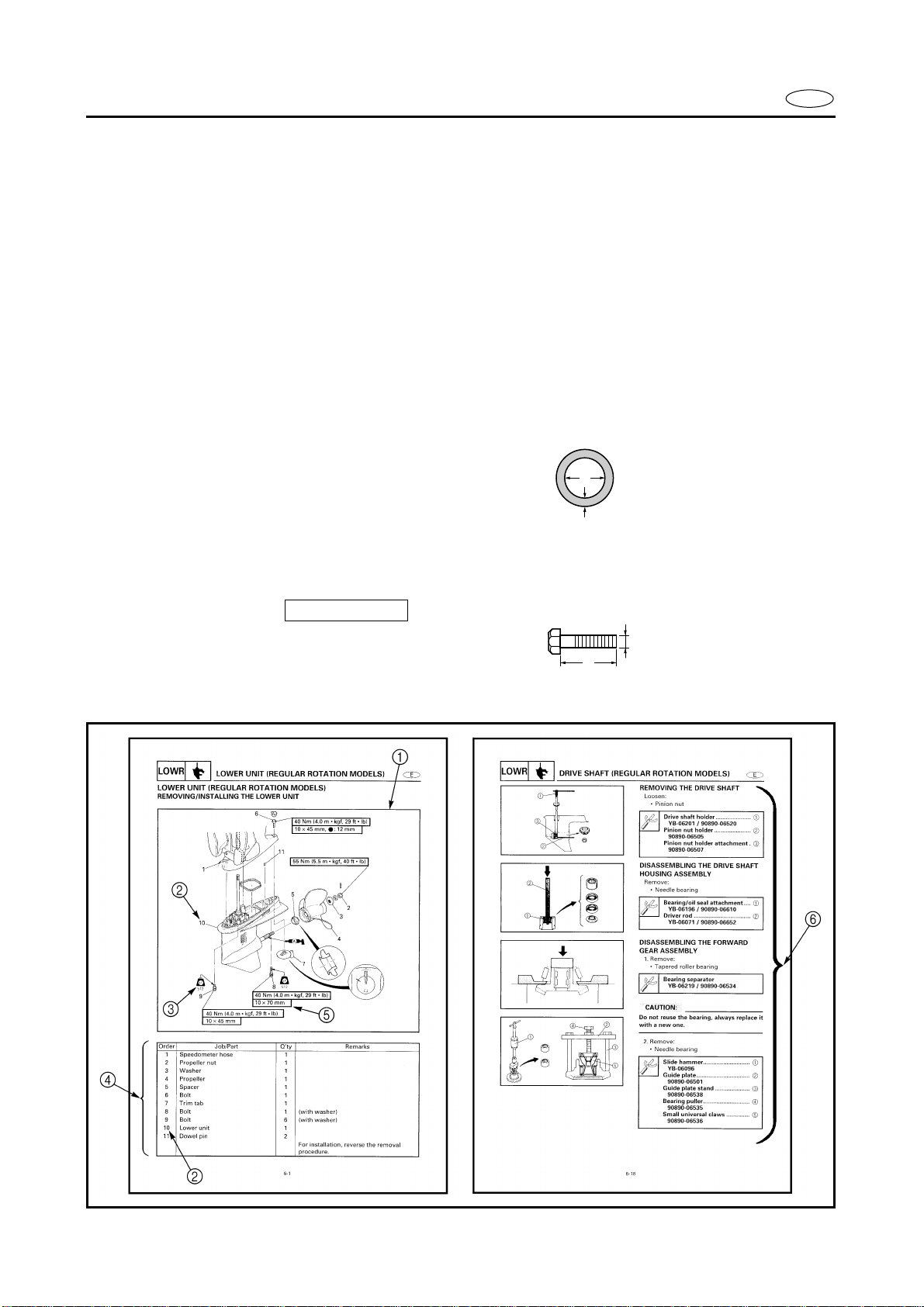
HOW TO USE THIS MANUAL
The main points regarding removing/installing and disassembling/assembling procedures
are shown in the exploded views.
The numbers in the exploded views indicate the required sequence of the procedure and
should be observed accordingly.
3
Symbols are used in the exploded views to indicate important aspects of the procedure.
A list of meanings for these symbols is provided on the following page.
4
It is important to refer to the job instruction charts at the same time as the exploded views.
These charts list the sequence that the procedures should be carried out in, as well as providing explanations on part names, quantities, dimensions and important points relating
to each relevant task.
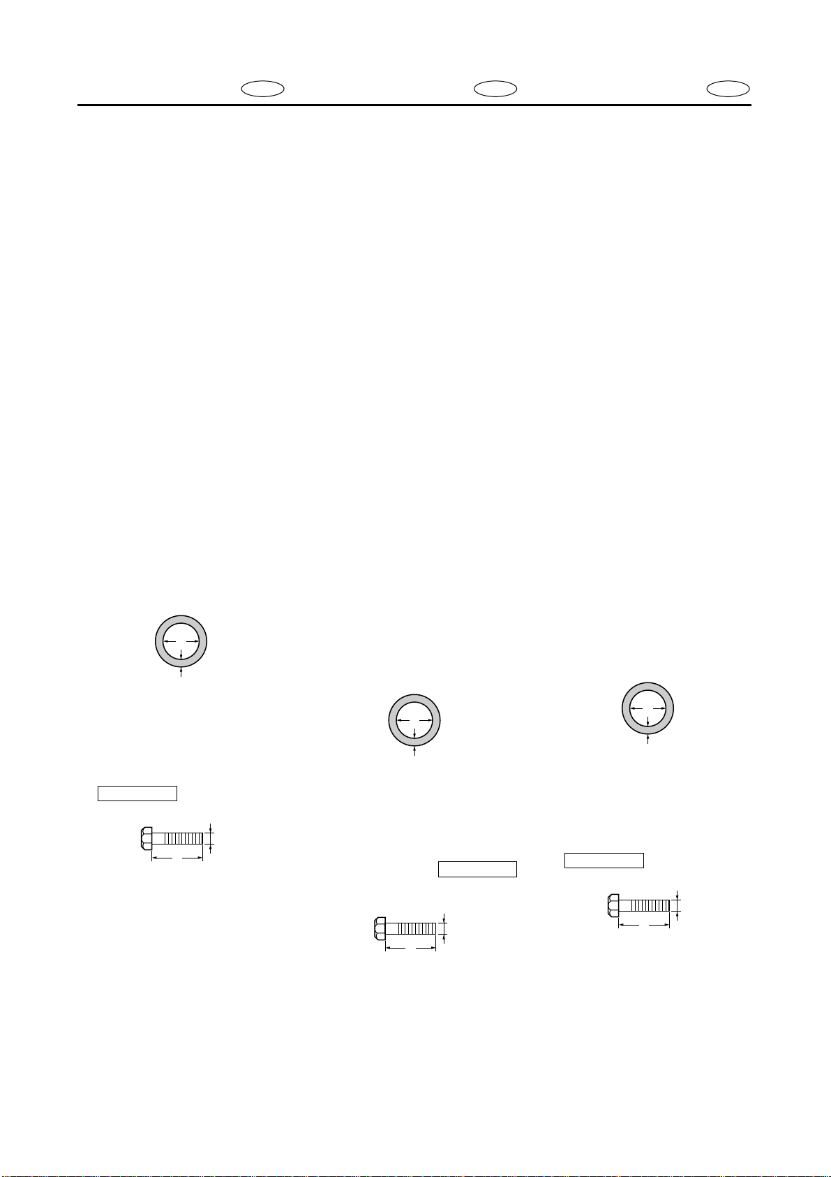
Example:
O-ring size 39.5 × 2.5 mm: inside diameter (D) × ring diameter (d)
E
D
d
5
In addition to tightening torques, the dimensions of the bolts and screws are also mentioned.
Example:
Bolt and screw size : bolt and screw diameter (D) × length (L)
6
In addition to the exploded views and job instruction charts, this manual provides individ-
10 × 25 mm
D
L
ual illustrations when further explanations are required to explain the relevant procedure.
F D
2
3
4
5
6
ES
STRUCTURE DU MANUEL
1
Les principaux points concernant les
procédures de dépose/installation et
de démontage/remontage sont illustrés sur les vues en éclaté.
2
Les numéros sur les vues en éclaté
indiquent l’ordre nécessaire de la
procédure et doivent être respectés
en conséquence.
3
Des symboles sont utilisés sur les
vues en éclaté pour indiquer les
aspects importants de la procédure.
Une liste de légendes de ces symboles figure sur la page suivante.
4
Il est important de se reporter aux
tableaux d’instructions en même
temps qu’aux vues en éclaté. Ces
tableaux énumèrent l’ordre dans
lequel les procédures doivent être
réalisées et apportent également des
explications sur le nom des pièces,
les quantités, les dimensions et des
points importants concernant chaque
tâche correspondante.
Exemple:
Taille du joint torique 39,5 × 2,5
mm: diamètre intérieur (D) × diamètre annulaire (d)
D
d
BENUTZUNG DIESES
HANDBUCHS
1
Die Hauptpunkte in Bezug auf
Verfahren für Ausbau/Einbau
und Demontage/Montage werden in den Explosionszeichnungen aufgezeigt.
Die Nummern in den Explosionszeichnungen zeigen den
erforderlichen Ablauf des Verfahrens an. Dieser sollte entsprechend befolgt werden.
In den Explosionszeichnungen
werden Symbole verwendet,
um wichtige Aspekte der Verfahren aufzuzeigen.
Eine Liste der Bedeutungen
dieser Symbole folgt auf der
nächsten Seite.
Es ist wichtig auf die Arbeitsanweisungstabelle sowie auf die
Explosionszeichnungen Bezug
zu nehmen. Diese Tabellen führen den Ablauf der Verfahren
auf, die durchgeführt werden
sollten. Ebenso sind Erklärungen bezüglich Teilbezeichnungen, Mengen, Abmessungen
und wichtige Punkte über jeden
Arbeitsvorgang angegeben.
Beispiel:
O-Ring Größe 39,5 × 2,5 mm:
Innendurchmesser (D) × Ringdurchmesser (d)
CÓMO EMPLEAR ESTE MANUAL
1
Los pasos principales que debe tener
en cuenta en el procedimiento de
extracción/instalación y de desmontaje/montaje de las piezas aparece en
ilustraciones detalladas.
2
Los números que aparecen en las
ilustraciones detalladas indican la
secuencia necesaria del procedimiento y debe mantenerse adecuadamente .
3
Los símbolos utilizados en las ilustraciones detalladas indican aspectos
importantes del procedimiento.
En la página siguiente encontrará
una lista del significado de los símbolos.
4
Es importante consultar las tablas de
instrucciones de los trabajos al
mismo tiempo que las ilustraciones
detalladas. Estas tablas indican la
secuencia en la que debe realizar el
procedimiento, además de proporcionar explicaciones correspondientes a la denominación de la pieza,
cantidad, dimensiones y aspectos
importantes relacionados con cada
tarea relevante.
Por ejemplo:
Tamaño de las juntas tóricas 39,5
2,5 mm: diámetro interno (D) × diámetro del aro (d)
×
5
En plus des couples de serrage, les
dimensions des boulons et des vis
sont également mentionnées.
Exemple:
Taille de boulon et de vis
10 × 25 mm
: diamètre de boulon
et de vis (D) × longueur (L)
D
L
6
En plus des vues en éclaté et des
tableaux d’instructions des tâches, ce
manuel présente des illustrations
individuelles lorsque d’autres précisions sont nécessaires pour expliquer
la procédure correspondante.
D
d
Zusätzlich zu den Anzugsdrehmomenten sind die Abmessungen der Bolzen und Schrauben
ebenfalls aufgeführt.
Beispiel:
Schraubengröße
10 × 25 mm
: Schraubendurchmesser (D) ×
Länge (L)
D
L
Zusätzlich zu den Explosionszeichnungen und Arbeitsanweisungstabellen gibt dieses
Handbuch einzelne Darstellungen, falls weitere Erklärungen
notwendig sind, um das entsprechende Verfahren zu erklären.
D
d
5
Además de la torsión de apriete, se
mencionan las dimensiones de los
pernos y los tornillos.
Por ejemplo:
Tamaño del perno y el tornillo
10 × 25 mm
: diámetro (D) × lon-
gitud (L) del perno y el tornillo
D
L
6
Además de las ilustraciones detalladas y las tablas de instrucciones de
los trabajos, este manual proporciona
ilustraciones individuales cuando se
requieran mayores explicaciones
sobre el procedimiento relevante.
1
2
3
4
5
6
7
8
9
0
A
B
C
D
E
F
G
H
E
12
GEN
INFO
34
SPEC
INSP
FUEL
ADJ
56
POWR
78
BRKT
90
LOWR
–+
ELEC
TRBL
ANLS
AB
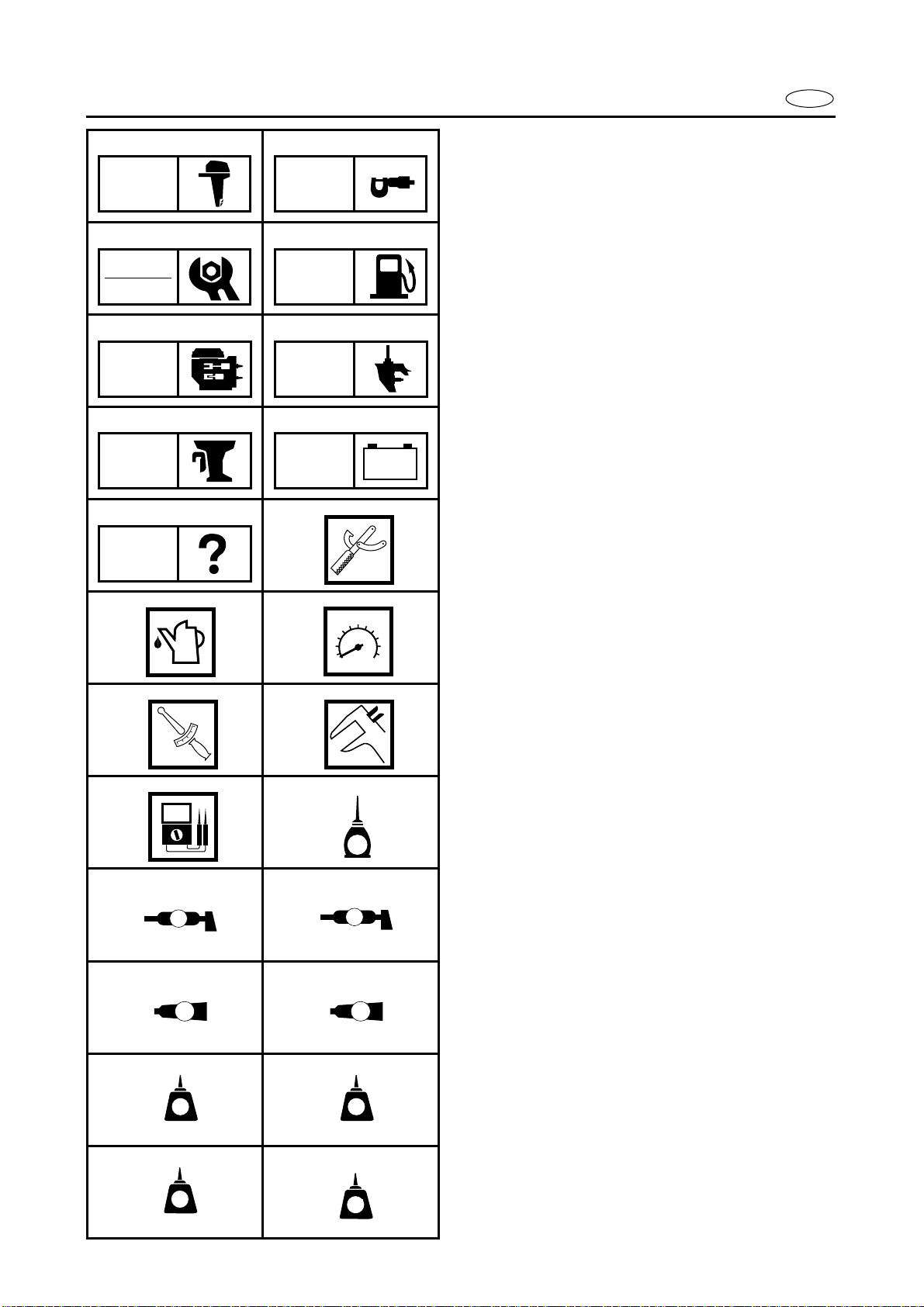
SYMBOLS
Symbols 1 to 9 are designed as thumbtabs to indicate the content of a chapter.
General information
Specifications
Periodic inspections and adjustments
Fuel system
Power unit
Lower unit
Bracket unit
Electrical systems
Trouble analysis
Symbols 0 to E indicate specific data.
Special tool
Specified liquid
Specified engine speed
Specified torque
Specified measurement
Specified electrical value
[Resistance (
(A)]
Ω
), Voltage (V), Electric current
CD
T
.
R
.
EF
E
GH
A
IJ
GM
KL
LT
271
MN
LT
572
M
LT
242
SS
LT
4
Symbol F to H in an exploded diagram
indicate the grade of lubricant and the location of the lubrication point.
Apply Yamaha 2-stroke outboard motor oil
(TC-W3)
Apply water resistant grease
(Yamaha grease A, Yamaha marine grease)
Apply molybdenum disulfide oil
Symbols I to N in an exploded diagram
indicate the grade of the sealing or locking
agent and the location of the application
point.
I Apply Gasket Maker
J Apply Yamabond #4
(Yamaha bond number 4)
K Apply LOCTITE No. 271 (Red LOCTITE)
L Apply LOCTITE No. 242 (Blue LOCTITE)
M Apply LOCTITE No. 572
N Apply silicon sealant

ES
F D
1
SYMBOLES
Les symboles
1
à
9
servent d’onglets
et indiquent le contenu des différents
chapitres:
Informations générales
2 Spécifications
3 Inspection périodique et réglage
4 Système d’alimentation
5 Moteur
6 Bloc de propulsion
7 Unité de support
8 Equipement électrique
9 Dépannage
Les symboles 0 à E apportent certaines
précisions:
0 Outillage spécial
A Liquide spécifié
B Vitesse du moteur spécifiée
C Couple spécifié
D Mesure spécifiée
E Valeur électrique spécifiée
[résistance (Ω), tension (V),
courant électrique (A)]
Les symboles F à H dans les vues en
éclaté donnent la qualité de lubrifiant à
employer et les points de graissage:
F Appliquer de l’huile moteur deux temps
Yamaha pour hors-bord (TC-W3)
G Appliquer de la graisse hydrofuge (graisse
Yamaha A, graisse Yamaha marine).
H Appliquer de l’huile au bisulphure de
molybdène.
Les symboles I à N dans les vues en
éclaté indiquent la qualité des liquides
d’étanchéité et de l’agent bloquant à
employer ainsi que les points d’application:
I Appliquer du Gasket marker.
J Appliquer du Yamabond n˚4
K Appliquer du LOCTITE n˚ 271
(LOCTITE rouge)
L Appliquer du LOCTITE
(LOCTITE bleu)
M Appliquer du LOCTITE n˚ 572
N Appliquer une pâte d’étanchéité au
silicone.
n˚ 242
SYMBOLE
Die Symbole 1 bis 9 sind Randmarkierungen, die auf den Inhalt
der einzelnen Kapitel hinweisen.
1 Allgemeines
2 Technische Daten
3 Regelmäßige Inspektionen und Ein-
stellungen
4 Kraftstoffanlage
5 Motor
6 Antriebseinheit
7 Motorhalterung
8 Elektrische Anlage
9 Störungssuche
Die Symbole 0 bis E zeigen spezifische Daten an:
0 Spezialwerkzeug
A Spezielle Flüssigkeit
B Vorgeschriebene Motordrehzahl
C Schrauben-Anzugsmoment
D Spezielle Messung
E Elektrischer Meßwert
[Widerstand (Ω), Spannung (V),
Stromstärke (A)]
Die Symbole F bis H zeigen in
einer Explosionszeichnung den
Schmiermitteltyp und die
Schmierstelle an:
F Yamaha-Zweitakt-Außenbordmo-
tor-öl auftragen (TC-W3)
G Wasserfestes Fett auftragen
(Yamaha-Fett A, Yamaha-Bootsfett)
H Molybdänsulfid-Öl auftragen
Die Symbole I bis N zeigen in
einer Explosionszeichnung den
Typ des Dichtungsmittels oder
Klebers und die Anwendungsstelle
an.
I Gasket maker auftragen
J Yamabond #4 auftragen
(Yamaha Klebstoff Nr. 4)
K LOCTITE
auftragen
L LOCTITE Nr. 242 (blaues LOCTITE)
auftragen
M LOCTITE Nr. 572 auftragen
N Silikon-Dichtungsmasse auftragen
Nr. 271 (rotes LOCTITE)
SÍMBOLOS
Los símbolos 1 a 9 identifican el contenidos de un capítulo.
1 Información general
2 Especificaciones
3 Inspección periódica y ajuste
4 Sistema de combustible
5 Motor
6 Unidad inferior
7 Unidad de ménsula
8 Sistemas eléctricos
9 Análisis de averías
Los símbolos 0 a E indican datos específicos:
0 Herramienta especial
A Líquido especificado
B Velocidad del motor especificada
C Torsión especificada
D Medición especificada
E Valor eléctrico especificado
[Resistencia (Ω), Tensión (V),
Corriente eléctrica (A)]
Los símbolos F a H de un diagrama
detallado indican el grado de lubricante y
la situación del punto de lubricación:
F Aplicar aceite de motor fuera de borda de
2 tiempos Yamaha (TC-W3)
G Aplicar grasa hidrófuga Yamaha (grasa
náutica A Yamaha, grasa náutica Yamaha)
H Aplicar aceite con bisulfuro de molibdeno
Los símbolos I a N de un diagrama
detallado indican el grado de la junta
líquida o compuesto obturante y la situación del punto de aplicación:
I Aplicar empaquetadura líquida de marca
J Aplique agente adhesivo Yamabond N.˚ 4
K Aplicar LOCTITE N.˚ 271
(LOCTITE rojo)
L Aplicar LOCTITE
(LOCTITE azul)
M Aplicar LOCTITE N.˚ 572
N Aplique agente de sellado silicónico
N.˚ 242

E
CONTENTS
GENERAL INFORMATION
SPECIFICATIONS
PERIODIC INSPECTIONS AND
ADJUSTMENTS
FUEL SYSTEM
POWER UNIT
LOWER UNIT
BRACKET UNIT
ELECTRICAL SYSTEMS
TROUBLE ANALYSIS

TABLE DES
MATIERES
INFORMATIONS
GENERALES
SPECIFICATIONS
INSPECTION
PERIODIQUE ET
REGLAGE
F
INHALT
ALLGEMEINES
TECHNISCHE
DATEN
REGELMÄßIGE
INSPEKTIONEN UND
EINSTELLUNGEN
D
TABLA DE
MATERIAS
INFORMACIÓN
GENERAL
ESPECIFICACIONES
INSPECCIÓN
PERIÓDICA Y
AJUSTE
ES
GEN
INFO
SPEC
INSP
ADJ
1
2
3
SYSTEME
D’ALIMENTATION
MOTEUR
BLOC DE
PROPULSION
UNITE DE SUPPORT
KRAFTSTOFFANLAGE
MOTOR
ANTRIEBSEINHEIT
MOTORHALTERUNG
SISTEMA DE
COMBUSTIBLE
MOTOR
UNIDAD INFERIOR
UNIDAD DE
MÉNSULA
FUEL
POWR
LOWR
BRKT
4
5
6
7
EQUIPEMENT
ELECTRIQUE
DEPANNAGE
ELEKTRISCHE
ANLAGE
STÖRUNGSSUCHE
SISTEMAS
ELÉCTRICOS
ANÁLISIS DE
AVERÍAS
–+
ELEC
TRBL
ANLS
8
9

GEN
INFO
CHAPTER 1
GENERAL INFORMATION
IDENTIFICATION ............................................................................................ 1-1
SERIAL NUMBER ..................................................................................... 1-1
STARTING SERIAL NUMBERS ............................................................... 1-1
E
SAFETY WHILE WORKING
FIRE PREVENTION ................................................................................... 1-2
VENTILATION........................................................................................... 1-2
SELF-PROTECTION.................................................................................. 1-2
OILS, GREASES AND SEALING FLUIDS................................................ 1-2
GOOD WORKING PRACTICES ................................................................ 1-3
DISASSEMBLY AND ASSEMBLY ........................................................... 1-4
SPECIAL TOOLS
MEASURING ............................................................................................ 1-5
REMOVING AND INSTALLING ............................................................... 1-7
............................................................................................. 1-5
............................................................................ 1-2

F D
ES
CHAPITRE 1
INFORMATIONS
GENERALES
IDENTIFICATION ............................. 1-1
NUMERO DE SERIE.......................1-1
NUMEROS DE DEBUT DE
SERIE .............................................. 1-1
MESURES DE SECURITE EN
TRAVAILLANT
MESURES DE PREVENTION
CONTRE LES INCENDIES ........... 1-2
AERATION ...................................... 1-2
PROTECTION PERSONNELLE.....1-2
HUILES, GRAISSES ET
LIQUIDES D’ETANCHEITE.........1-2
BONNES PRATIQUES DE
TRAVAIL........................................1-3
DEMONTAGE ET
REMONTAGE ................................ 1-4
OUTILLAGE SPECIAL .................... 1-5
MESURE........................................... 1-5
DEPOSE ET INSTALLATION........ 1-7
................................ 1-2
KAPITEL 1
ALLGEMEINES
KENNUMMER ................................ 1-1
SERIENNUMMER ...................... 1-1
ANFANGS-SERIENNUMMERN..1-1
SICHERHEITSMASSNAHMEN ..... 1-2
BRANDSCHUTZ ......................... 1-2
BELÜFTUNG .............................. 1-2
SELBSTSCHUTZ ........................1-2
ÖLE, SCHMIERSTOFFE UND
DICHTUNGSMITTEL.................1-2
RICHTIGE
ARBEITSGEWOHNHEITEN ......1-3
DEMONTAGE UND
MONTAGE ................................ 1-4
SPEZIALWERKZEUGE ................... 1-5
MESSGERÄTE............................ 1-5
AUSBAU UND EINBAU ............. 1-7
CAPITULO 1
INFORMACIÓN
GENERAL
IDENTIFICACIÓN ............................ 1-1
NÚMERO DE SERIE.......................1-1
NÚMEROS DE SERIE
INICIALES...................................... 1-1
SEGURIDAD EN EL TRABAJO ...... 1-2
PREVENCIÓN DE INCENDIOS .... 1-2
VENTILACIÓN................................ 1-2
AUTOPROTECCIÓN ...................... 1-2
ACEITES, GRASAS Y LÍQUIDOS
OBTURANTES...............................1-2
PROCEDIMIENTO DE TRABAJO
CORRECTOS.................................. 1-3
DESMONTAJE Y MONTAJE.........1-4
HERRAMIENTAS ESPECIALES .... 1-5
MEDICIÓN....................................... 1-5
EXTRACCIÓN E
INSTALACIÓN .............................. 1-7
1
2
3
4
5
6
7
8
9
1
2
3
4
GEN
INFO
S6E51010
IDENTIFICATION
IDENTIFICATION 1
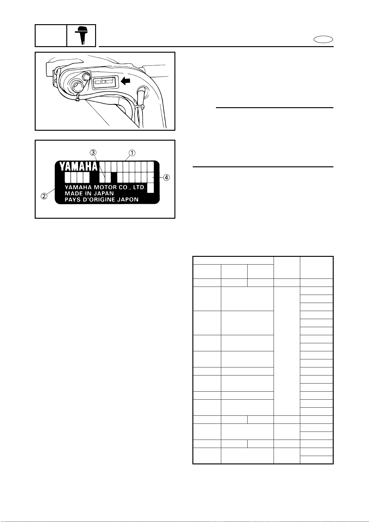
SERIAL NUMBER
The outboard motor’s serial number is
stamped on a label which is attached to the
port clamp bracket.
NOTE:
As an antitheft measure, a special label on
which the outboard motor’s serial number
is stamped is bonded to the port clamp
bracket. The label is specially treated so
that peeling it off causes cracks across the
serial number.
Model name
Approval model code
Transom height
Serial number
E
1020
STARTING SERIAL NUMBERS
The starting serial number blocks are as follows:
Model name
World-
wide
100AETO — 100TR 64W L: 301207 -
E115AMH —
E115AWH —
E115AE —
E115AET —
115BE — L: 420111 -
115BET C115TR
115BETO — L: 369029 -
115CETO 115TR, S115TR
— B115TR — 66Y L: 000301 -
130BETO 130TR, S130TR 6L1
L130BETO L130TR — 6L6 X: 701971 -
140BET — 6F3
USA Canada
Approval
model
code
6E5
Starting
serial
number
L: 020299 -
Y: 120287 -
X: 220247 -
L: 040218 -
Y: 141565 -
X: 240241 -
L: 001784 -
X: 760102 -
L: 014822 -
X: 211575 -
L: 332717 -
X: 523972 -
L: 404067 -
X: 729696 -
L: 310563 -
X: 705725 -
L: 522075 -
X: 421113 -
1-1
F D
1-
1
2
3
4
1
2
3
4
1
2
3
4
IDENTIFICATION
GEN
INFO
KENNUMMER
IDENTIFICACIÓN
ES
IDENTIFICATION
NUMERO DE SERIE
Le numéro de série du moteur hors-bord
est estampé sur une étiquette qui est
fixée du côté bâbord du support de serrage.
N.B.:
A titre de mesure antivol, une étiquette
spéciale sur laquelle est estampé le
numéro de série du moteur hors-bord est
attachée au support de serrage bâbord.
L’étiquette a subi un traitement spécial
de sorte qu’en la décollant le numéro de
série se fissure.
Nom de modèle
Code d’agrément de modèle
Hauteur de barre d’arcasse
Numéro de série
NUMEROS DE DEBUT DE SERIE
Les blocs numéros de début de série sont
les suivants:
Nom de modèle Code de
Universel E.-U. Canada
100AETO — 100TR 64W L: 301207 -
E115AMH —
E115AWH —
E115AE —
E115AET —
115BE — L: 420111 -
115BET C115TR
115BETO — L: 369029 -
115CETO 115TR, S115TR
— B115TR — 66Y L: 000301 -
130BETO 130TR, S130TR 6L1
L130BETO L130TR — 6L6 X: 701971 -
140BET — 6F3
modèle
agréé
6E5
Numéro
de début
de série
L: 020299 Y: 120287 X: 220247 L: 040218 Y: 141565 X: 240241 L: 001784 X: 760102 L: 014822 X: 211575 -
L: 332717 X: 523972 -
L: 404067 X: 729696 -
L: 310563 X: 705725 -
L: 522075 X: 421113 -
KENNUMMER
SERIENNUMMER
Die Seriennummer des Außenbordmotors ist auf ein Etikett eingestanzt, das auf der linken Seite
der Klemmhalterung angebracht
ist.
HINWEIS:
Als Diebstahlsicherung ist die
Seriennummer des Außenbordmotors auf ein Spezialetikett eingestanzt, das auf der linken Seite
der Klemmhalterung angebracht
ist. Das Etikett ist speziell behandelt, so daß das Abziehen Risse
über der Seriennummer hinterläßt.
Modellbezeichnung
Modell-Zulassungsnummer
Spiegelhöhe
Seriennummer
ANFANGS-SERIENNUMMERN
Die Nummernblöcke der AnfangsSeriennummern sind wie folgt:
Modellbezeichnung Geneh-
Weltweit USA Kanada
100AETO — 100TR 64W L: 301207 -
E115AMH
E115AWH
E115AE —
E115AET
115BE — L: 420111 -
115BET C115TR
115BETO
115CETO
— B115TR — 66Y L: 000301 -
130BETO
L130BETO L130TR — 6L6 X: 701971 -
140BET — 6F3
—
—
—
— L: 369029 -
115TR,
S115TR
130TR,
S130TR
migung
Modell-
Zulassungs-
nummer
6E5
6L1
Anfangs-
Serien-
nummer
L: 020299 Y: 120287 X: 220247 -
L: 040218 Y: 141565 X: 240241 -
L: 001784 X: 760102 -
L: 014822 X: 211575 -
L: 332717 X: 523972 -
L: 404067 X: 729696 -
L: 310563 X: 705725 -
L: 522075 X: 421113 -
IDENTIFICACIÓN
NÚMERO DE SERIE
El número de serie del motor fuera borda
está impreso en una etiqueta colocada a
babor del soporte mordaza.
NOTA:
Como medida de seguridad anti-robos,
hay una etiqueta especial que tiene
impreso el número de serie del motor
fuera borda colocada a babor del soporte
mordaza. Esta etiqueta lleva una tratamiento especial de forma que si se
extrae, el número de serie queda agrietado.
Número del modelo
Código de aprobación del modelo
Altura del peto
Número de serie
NÚMEROS DE SERIE INICIALES
Los bloques de números de serie iniciales son los siguientes:
Nombre del modelo Código
Interna-
100AETO — 100TR 64W L:301207 -
E115AMH —
E115AWH —
E115AE —
E115AET —
115BET C115TR
115BETO — L: 369029 -
115CETO 115TR, S115TR
130BETO 130TR, S130TR 6L1
L130BETO L130TR — 6L6 X:701971 -
140BET — 6F3
EE.UU. Canadá
cional
115BE — L:420111 -
— B115TR — 66Y L:000301 -
de apro-
bación
del
modelo
6E5
Número
de serie
inicial
L:020299 Y:120287 X:220247 L:040218 Y:141565 X:240241 L:001784 X:760102 L:014822 X:211575 -
L:332717 X:523972 -
L:404067 X:729696 -
L:310563 X:705725 -
L:522075 X:421113 -
1 1-2
1
GEN
INFO
SAFETY WHILE WORKING
E
SAFETY WHILE WORKING 1
The procedures given in this manual are
those recommended by Yamaha to be followed by Yamaha dealers and their
mechanics.
FIRE PREVENTION
Gasoline (petrol) is highly flammable.
Petroleum vapor is explosive if ignited.
Do not smoke while handling gasoline and
keep it away from heat, sparks and open
flames.
1030
1040
1050
VENTILATION
Petroleum vapor is heavier than air and is
deadly if inhaled in large quantities. Engine
exhaust gases are harmful to breathe.
When test-running an engine indoors,
maintain good ventilation.
SELF-PROTECTION
Protect your eyes with suitable safety
glasses or safety goggles, when grinding or
when doing any operation which may
cause particles to fly off. Protect hands and
feet by wearing safety gloves or protective
shoes if appropriate to the work you are
doing.
1060
OILS, GREASES AND SEALING
FLUIDS
Use only genuine Yamaha oils, greases and
sealing fluids or those recommended by
Yamaha.

GEN
INFO
F D
1-
MESURES DE SECURITE EN TRAVAILLANT
SICHERHEITSMASSNAHMEN
SEGURIDAD EN EL TRABAJO
ES
MESURES DE SECURITE
EN TRAVAILLANT
Les procédures décrites dans ce manuel
sont recommandées par Yamaha et doivent être respectées par les concessionnaires Yamaha et leurs mécaniciens.
MESURES DE PREVENTION
CONTRE LES INCENDIES
L’essence est hautement inflammable.
Les vapeurs d’essence sont explosives
lorsqu’elles sont enflammées.
Ne pas fumer lors de la manipulation
d’essence. Maintenir l’essence à l’écart
des sources de chaleur, des étincelles et
des flammes.
AERATION
Les vapeurs d’essence sont plus lourdes
que l’air et sont mortelles si elles sont
inhalées en grandes quantités. Il est nocif
d’inhaler des gaz d’échappement.
Lors d’essais de fonctionnement d’un
moteur en intérieur, s’assurer que
l’endroit est bien aéré.
PROTECTION PERSONNELLE
Protégez-vous les yeux à l’aide de lunettes de sécurité adéquates lorsque vous
meulez ou effectuez n’importe quelle
opération risquant de projeter des particules. Se protéger également les mains et
les pieds avec des gants de sécurité et des
chaussures de protection si nécessaire.
HUILES, GRAISSES ET LIQUIDES
D’ETANCHEITE
N’utilisez que les huiles, graisses et
liquides d’étanchéité Yamaha ou ceux
recommandés par Yamaha.
SICHERHEITSMASSNAHMEN
Die in diesem Handbuch angegebenen Maßnahmen sind von
Yamaha empfohlen und von den
Yamaha-Händlern und ihren
Mechanikern zu beachten.
BRANDSCHUTZ
Kraftstoff (Benzin) ist leicht entflammbar.
Benzindämpfe sind hochexplosiv.
Kraftstoff auf gar keinen Fall in der
Nähe von Funken oder Flammen
handhaben. Niemals rauchen,
wenn mit Kraftstoff hantiert wird.
BELÜFTUNG
Benzindämpfe sind schwerer als
Luft. Bei längerem Einatmen dieser Dämpfe besteht Lebensgefahr. Auch das Einatmen von
Motorabgasen ist gesundheitsschädlich.
Beim Probelauf eines Motors in
geschlossenen Räumen für ausreichende Belüftung sorgen.
SELBSTSCHUTZ
Bei Schleifarbeiten oder sonstigen Arbeiten, bei denen Metallsplitter oder andere Teilchen
freigesetzt werden, eine geeignete Schutzbrille oder -maske aufsetzen. Zum Schutz der Hände und
Füße, wenn angebracht, stets
Sicherheitsschuhe und -handschuhe tragen.
ÖLE, SCHMIERSTOFFE UND
DICHTUNGSMITTEL
Nur von Yamaha hergestellte oder
empfohlene Öle, Schmierstoffe
und Dichtungsmittel verwenden.
SEGURIDAD EN EL
TRABAJO
Los procedimientos incluidos en este
manual son los que Yamaha recomienda
a sus concesionarios y mecánicos.
PREVENCIÓN DE INCENDIOS
La gasolina (petróleo) es altamente inflamable.
El vapor del petróleo es explosivo si se
enciende.
No fume mientras manipula con gasolina
(petróleo) y manténgala alejada del
calor, chispas y llamas.
VENTILACIÓN
El vapor del petróleo es más pesado que
el aire y puede provocar la muerte si se
inhala en grandes cantidades. La inhalación de los gases de escape del motor son
perjudiciales.
Cuando compruebe el mantenimiento de
un motor en un lugar cerrado, mantenga
el lugar bien ventilado.
AUTOPROTECCIÓN
Protéjase los ojos con gafas adecuadas
de seguridad esmerile o cuando realice
cualquier operación que provoque el desprendimiento de partículas. Protéjase
manos y pies con guantes de seguridad o
zapatos apropiados para el trabajo a realizar.
ACEITES, GRASAS Y LÍQUIDOS
OBTURANTES
Utilice siempre aceites, grasas y líquidos
obturantes genuinos Yamaha u otros
recomendados por Yamaha.
2 1-3
2
GEN
INFO
SAFETY WHILE WORKING
E
Under normal conditions of use, there
should be no hazards from the use of the
lubricants mentioned in this manual, but
safety is all-important, and by adopting
good safety practices, any risk is minimized.
A summary of the most important precautions is as follows:
1. While working, maintain good standards of personal and industrial
hygiene.
2. Clothing which has become contaminated with lubricants should be
changed as soon as practicable, and
laundered before further use.
3. Avoid skin contact with lubricants; do
not, for example, place a soiled wipingrag in your pocket.
4. Hands and any other part of the body
which have been in contact with lubricants or lubricant-contaminated clothing, should be thoroughly washed with
hot water and soap as soon as practicable.
5. To protect the skin, the application of a
suitable barrier cream to the hands
before working, is recommended.
6. A supply of clean lint-free cloths should
be available for wiping purposes.
1070
GOOD WORKING PRACTICES
1. The right tools
Use the recommended special tools to
protect parts from damage. Use the
right tool in the right manner – do not
improvise.
2. Tightening torque
Follow the tightening torque instructions. When tightening bolts, nuts and
screws, tighten the large sizes first, and
tighten inner-positioned fixings before
outer-positioned ones.

MESURES DE SECURITE EN TRAVAILLANT
GEN
INFO
En conditions normales d’utilisation, il
ne devrait pas y avoir de danger lié à
l’utilisation des lubrifiants indiqués dans
ce manuel. Néanmoins, il convient de
prendre toutes les mesures de sécurité
nécessaires afin de minimiser les risques.
Observez les principales consignes suivantes:
1. En travaillant, respectez les règles
d’hygiène personnelle et professionnelle qui s’imposent.
2. Les vêtements qui ont été souillés
par les lubrifiants doivent être
changés dès que possible et lavés
avant toute nouvelle utilisation.
3. Evitez le contact des lubrifiants
avec la peau, ne mettez pas, par
exemple, un chiffon imbibé de l’un
de ces produits dans votre poche.
4. Si les mains ou d’autres parties du
corps ont été en contact avec des
lubrifiants ou des vêtements
souillés par ces produits, lavez-les
bien à l’eau chaude et au savon dès
que possible.
5. Il est recommandé de se protéger
les mains avec une crème appropriée avant de travailler.
6. Prévoyez toujours une réserve de
chiffons propres et non pelucheux.
BONNES PRATIQUES DE
TRAVAIL
1. Outillage correct
Utilisez les outils spéciaux conseillés afin d’éviter d’endommager
les pièces. Utilisez toujours l’outil
convenant au travail à effectuer. –
N’improvisez pas.
2. Couple de serrage
Respectez les couples de serrage
spécifiés. Lors du serrage des boulons, des écrous ou des vis, serrez
tout d’abord les fixations ayant le
plus grand diamètre, en allant du
centre vers l’extérieur.
SICHERHEITSMASSNAHMEN
SEGURIDAD EN EL TRABAJO
F D
Unter normalen Gebrauchsbedingungen sollten die in diesem
Handbuch aufgeführten Schmierstoffe keine Gefahr darstellen. Da
Sicherheit jedoch oberstes Gebot
ist, sollten einige Sicherheitsmaßnahmen eingehalten werden, um
jegliches Risiko auf das mindeste
zu begrenzen.
Nachstehend eine Übersicht der
wichtigsten Vorsichtsmaßnahmen:
1. Während der Arbeit immer
für saubere, gut sitzende
Arbeitskleidung und einen
sauberen Arbeitsplatz sorgen.
2. Durch Schmiermittel verschmutzte Kleidung bei der
ersten Gelegenheit wechseln
und vor weiterer Benutzung
gründlich reinigen lassen.
3. Vermeiden, Schmiermittel mit
der Haut in Berührung zu
bringen (z.B. ölige Lappen
nicht in die Tasche stecken).
4. Hände und andere Körperteile, die in Kontakt mit
Schmiermitteln oder verschmutzter Kleidung gekommen sind, möglichst schnell,
gründlich mit warmem Wasser und Seife waschen.
5. Zum Schutz der Haut wird vor
Arbeitsbeginn das Auftragen
einer geeigneten Schutzcreme empfohlen.
6. Stets einen Vorrat fusselfreier Putztücher oder saugfähiges Papier bereithalten.
RICHTIGE
ARBEITSGEWOHNHEITEN
1. Die richtigen Werkzeuge
Die Verwendung von Spezialwerkzeug trägt in erheblichem Maße dazu bei, die zu
wartenden Teile vor Beschädigung zu schützen. Das
Werkzeug muß in der vorgeschriebenen Art und Weise
benutzt werden. – Keine
Behelfsmethoden und -mittel.
2. Anzugsdrehmoment
Die Anweisungen über die
Anzugsdrehmomente beachten. Beim Festziehen von
Schrauben und Muttern erst
die größeren Schrauben
anziehen. Innenliegende
Schrauben prinzipiell vor
außenliegenden festziehen.
1- 3
En condiciones normales de uso, el
empleo de los lubricantes mencionados
en este manual no debe plantear ningún
riesgo, pero la seguridad es un tema de
máxima importancia, por lo que la adopción de algunas medidas de seguridad
puede reducir los posibles riesgos.
A continuación se incluye un resumen de
las precauciones más importantes:
1. Cuando trabaje, mantenga una
higiene personal e industrial
correcta.
2. La ropa contaminada con lubricante debe cambiarse tan pronto
como sea posible y lavarse antes de
volver a ser usada.
3. Evite el contacto de la piel con los
lubricantes, por ejemplo, no introduzca un trapo impregnado en el
bolsillo.
4. Las manos y cualquier otra parte
del cuerpo que haya estado en contacto con lubricantes o ropa contaminada por lubricantes deben
lavarse minuciosamente con agua
caliente y jabón tan pronto como
sea posible.
5. Para proteger la piel, se recomienda
aplicar una crema protectora apropiada en las manos antes de iniciar
el trabajo.
6. Debe disponer de paños limpios
que no dejen pelusa para fines de
limpieza.
PROCEDIMIENTO DE TRABAJO
CORRECTOS
1. Las herramientas correctas
Utilice las herramientas especiales
recomendadas para evitar dañar las
piezas. Utilice la herramienta
correcta de la manera apropiada –
no improvise.
2. Torsión de apriete
Siga las instrucciones relacionadas
con la torsión de apriete. Cuando
apriete pernos, tuercas y tornillos,
apriete en primer lugar los de
mayor tamaño y apriete los situados en la parte interior antes de
apretar los situados en la parte
exterior.
ES
3 1-4
GEN
INFO
SAFETY WHILE WORKING
3. Non-reusable items
Always use new gaskets, packings, Orings, split-pins, circlips, etc., on reassembly.
1080
DISASSEMBLY AND ASSEMBLY
1. Clean parts with compressed air when
disassembling.
2. Oil the contact surfaces of moving parts
before assembly.
E
1090
1100
3. After assembly, check that moving parts
operate normally.
4. Install bearings with the manufacturer’s
markings on the side exposed to view,
and liberally oil the bearings.
5. When installing oil seals, apply a light
coating of water-resistant grease to the
outside diameter.

MESURES DE SECURITE EN TRAVAILLANT
GEN
INFO
3. Pièces à usage unique
Lors du remontage, utilisez toujours des joints, garnitures, joints
toriques, goupilles fendues, circlips, etc. neufs.
DEMONTAGE ET REMONTAGE
1. Lors du démontage, nettoyez les
pièces à l’air comprimé.
2. Lors du montage, huilez les surfaces de contact des pièces mobiles.
3. Après le montage, vérifiez que les
pièces mobiles fonctionnent normalement.
4. Montez les roulements avec la marque du fabricant vers l’extérieur et
huilez-les généreusement.
5. Lors du montage des joints étanches à l’huile, appliquez une légère
couche de graisse hydrofuge sur le
diamètre extérieur.
SICHERHEITSMASSNAHMEN
SEGURIDAD EN EL TRABAJO
3. Nicht wiederverwendbare
Teile
Beim Wiedereinbau stets
neue Dichtungen, Dämmstoffe, O-Ringe, Splinte,
Sicherungsringe usw. verwenden.
DEMONTAGE UND MONTAGE
1. Ausgebaute Teile mit Druckluft reinigen.
2. Kontaktflächen beweglicher
Teile beim Einbau mit Öl
schmieren.
3. Nach der Montage bewegliche Teile auf gute Funktion
prüfen.
4. Lager so einsetzen, daß die
Herstellerkennzeichen sichtbar bleiben. Lager großzügig
schmieren.
5. Beim Einbau von Wellendichtungen, diese außen leicht
mit einer dünnen Schicht
wasserbeständigen Fetts versehen.
F D
1- 4
ES
3. Elementos no reutilizables
Utilice siempre empaquetaduras,
juntas tóricas, pasadores hendidos,
retenedores, etc, nuevos cuando
vuelva a montar los componentes.
DESMONTAJE Y MONTAJE
1. Limpie las piezas con aire comprimido al desmontarlas.
2. Engrase las superficies de contacto
de las piezas móviles antes de montarlas.
3. Tras el montaje, compruebe que las
piezas móviles funcionan con normalidad.
4. Instale los cojinetes con las marcas
del fabricante encaradas hacia el
lado que queda expuesto a la vista
y engráselo abundantemente.
5. Cuando instale sellos de aceite,
aplique una capa de grasa hidrófuga en el diámetro exterior.
4 1-5
GEN
INFO
1
a
1
SPECIAL TOOLS
b
E
SPECIAL TOOLS 1
Using the correct special tools recommended by Yamaha, will aid the work and
enable accurate assembly and tune-up.
Improvising and using improper tools can
damage the equipment.
NOTE:
• For U.S.A. and Canada, use part numbers
that start with “J-”, “YB-”, “YM-”, “YU-”
or “YW-”.
• For others countries, use part numbers
that start with “90890-”.
23
45
67
89
0A
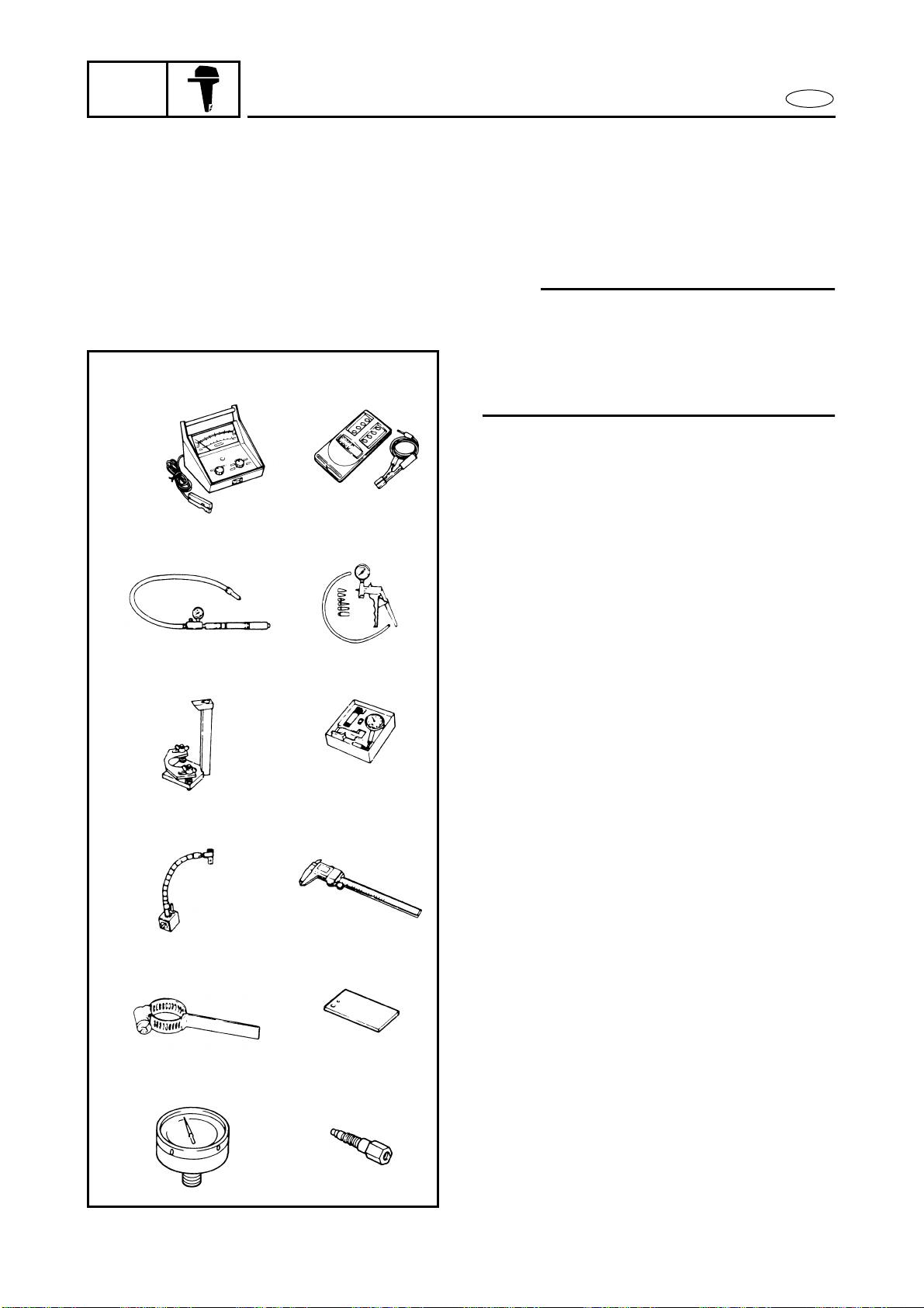
MEASURING
Tachometer
P/N. YU-08036-A ............................ a
90890-06760 ........................... b
2
Pressure tester
P/N. YB-35956
90890-06762
3
Mity vac
P/N. YB-35956
90890-06756
4
Pinion height gauge
P/N. YB-34432-6, YB-34432-11,
YB-34432-97
90890-06702
5
Dial gauge set
P/N. YU-03097
90890-01252
6
Magnetic base
P/N. YU-34481
90890-06705
7
Digital caliper
P/N. 90890-06704
8
Backlash indicator
P/N. YB-06265
90890-06706
9
Magnetic base attaching plate
P/N. YB-07003
90890-07003
0
Hydraulic pressure gauge
P/N. 90890-06776
A
Up-relief valve attachment
P/N. 90890-06773
Down-relief valve attachment
P/N. 90890-06774

GEN
INFO
OUTILLAGE SPECIAL
SPEZIALWERKZEUGE
HERRAMIENTAS ESPECIALES
F D
1-
ES
OUTILLAGE SPECIAL
Pour une plus grande précision dans votre
travail de montage et de mise au point,
Yamaha vous recommande l’emploi
d’outils spéciaux. Les improvisations ou
l’utilisation d’outils non appropriés peuvent endommager le matériel.
N.B.:
• Pour les Etats-Unis et le Canada, utilisez les pièces dont la référence commence par “J-”, “YB - ”, “YM - ”, “YU - ”
ou “YW-”.
• Pour les autres pays, utiliser les pièces
dont la référence commence par
“90890-”.
MESURE
1
Compte-tours
P/N. YU-08036-A ................. a
90890-06760................. b
2
Testeur de pression
P/N. YB-35956
90890-06762
3
Mity vac
P/N. YB-35956
90890-06756
4
Jauge de hauteur de pignon
P/N. YB-34432-6, YB-34432-11,
YB-34432-97
90890-06702
5
Ensemble pour jauge de cylindre
P/N. YU-03097
90890-01252
6
Base magnétique
P/N. YU-34481
90890-06705
7
Pied à coulisse numérique
P/N. 90890-06704
8 Indicateur de jeu de retour
P/N. YB-06265
90890-06706
9 Plaque de fixation de base magnéti-
que
P/N. YB-07003
90890-07003
0 Indicateur de pression hydraulique
P/N. 90890-06776
A Fixation de soupape de sûreté vers
le haut
P/N. 90890-06773
Fixation de soupape de sûreté vers
le bas
P/N. 90890-06774
SPEZIALWERKZEUGE
Die Verwendung der von Yamaha
empfohlenen Spezialwerkzeuge
erleichtert die Arbeit und ermöglicht genaue Montage und Einstellung. Behelfsmethoden und
falsches Werkzeug hingegen können erhebliche Schäden am Material verursachen.
HINWEIS:
• Werkzeugnummern, die mit
“J-”, “YB-”, “YM-”, “YU-” oder
“YW-” beginnen, beziehen sich
auf die USA und Kanada.
• Für andere Länder gelten die
Teilenummern, die mit “90890-”
beginnen.
MESSGERÄTE
1 Drehzahlmesser
P/N. YU-08036-A............... a
90890-06760.............. b
2 Drucktester
P/N. YB-35956
90890-06762
3 Mity vac
P/N. YB-35956
90890-06756
4 Ritzelhöhenmesser
P/N. YB-34432-6, YB-34432-11,
YB-34432-97
90890-06702
5 Meßuhr-Satz
P/N. YU-03097
90890-01252
6 Magnetische Basis
P/N. YU-34481
90890-06705
7 Digitale Schiebelehre
P/N. 90890-06704
8 Rückschlagsanzeiger
P/N. YB-06265
90890-06706
9 Verbindungsplatte für die
magnetische Basis
P/N. YB-07003
90890-07003
0 Hydraulischer Druckmesser
P/N. 90890-06776
A Überdruckventil-Einsatz
P/N. 90890-06773
Unterdruckventil-Einsatz
P/N. 90890-06774
HERRAMIENTAS
ESPECIALES
La utilización de las herramientas especiales recomendadas por Yamaha le ayudará en el trabajo y asegurará un montaje
y puesta a punto con precisión. La
improvisación y el empleo de herramientas incorrectas puede dañar el equipo.
NOTA:
• Para EE.UU y Canadá, utilice los
números de pieza que empiecen por
“J-”, “YB-”, “YM-”, “YU-” o “YW-”.
• Para otros países, utilice los números
de piezas que empiecen por “90890-”.
MEDICIÓN
1 Tacómetro
P/N.˚ YU-08036-A................. a
90890-06760................. b
2 Probador de presión
P/N.˚ YB-35956
90890-06762
3 Mity vac
P/N.˚ YB-35956
90890-06756
4 Medidor de altura de piñón
P/N.˚ YB-34432-6, YB-34432-11,
YB-34432-97
90890-06702
5 Calibre de cuadrante
P/N.˚ YU-03097
90890-01252
6 Base magnética
P/N.˚ YU-34481
90890-06705
7 Calibrador digital
P/N.˚ 90890-06704
8 Indicador de contragolpe
P/N.˚ YB-06265
90890-06706
9 Placa de colocación de la base mag-
nética
P/N.˚ YB-07003
90890-07003
0 Medidor de presión hidráulica
P/N.˚ 90890-06776
A Instalador de la válvula de seguri-
dad ascendente
P/N.˚ 90890-06773
Instalador de la válvula de seguridad descendente
P/N.˚ 90890-06774
5
5
GEN
INFO
B
C
a
D
EF
SPECIAL TOOLS
b
ba
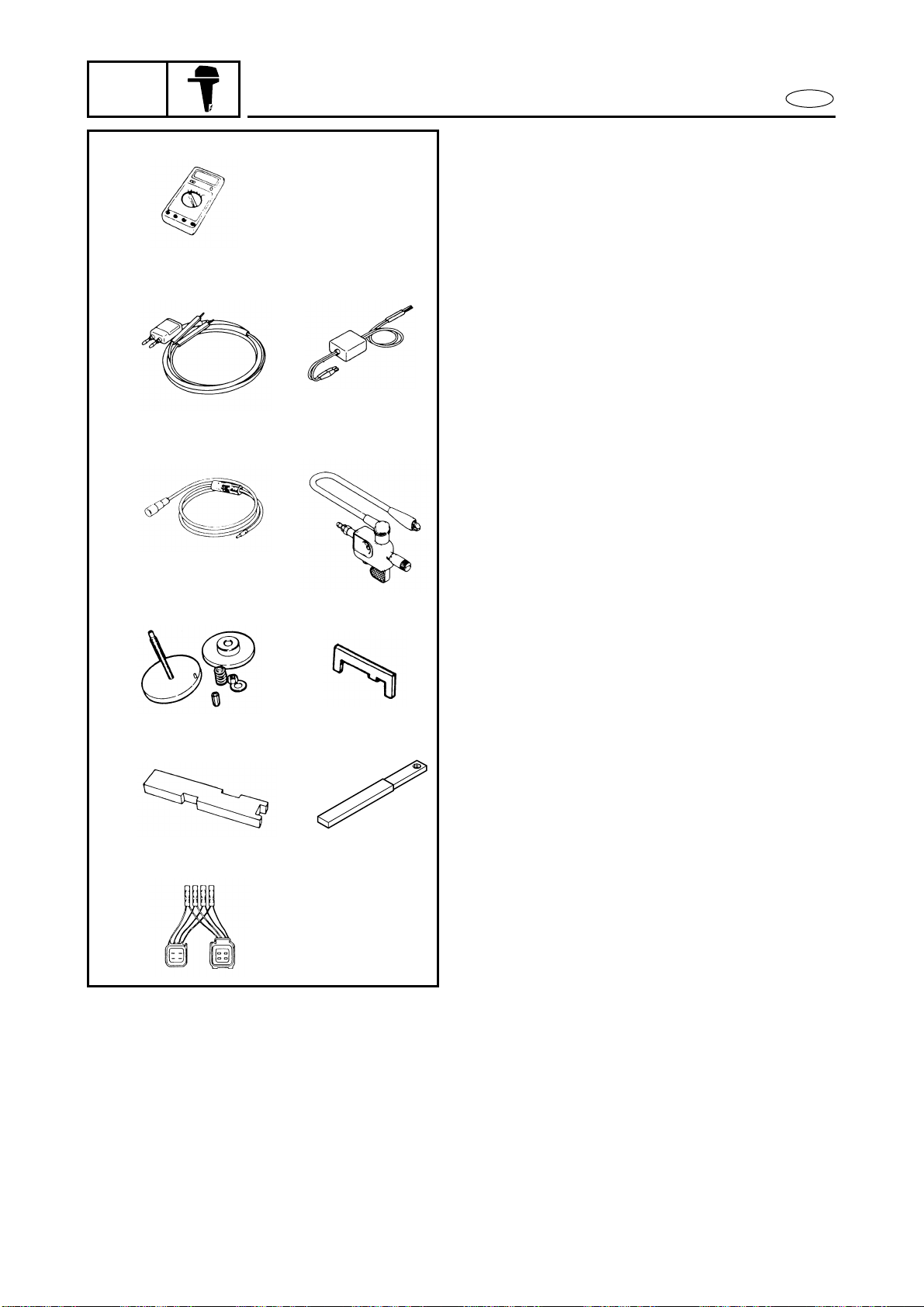
B
Digital tester
P/N. J-39299
90890-06752
C
Peak voltage adapter
P/N. YU-39991................................ a
90890-03169 ........................... b
D
Spark gap tester
P/N. YM-34487 ............................... a
90890-06754 ........................... b
E
Shimming gauge
P/N. YB-34446-1, YB-34446-3,
YB-34446-5, YB-34446-7
F
Shimming gauge
P/N. YB-34468-2
G
Shimming plate
P/N. 90890-06701
H
Shift rod wrench
P/N. YB-06052
90890-06052
I
Test harness
P/N. YB-06770, YB-38831,
YB-38832
90890-06770, 90890-06771
E
GH
I
1-6
Loading...