


XL™ Series
Models |
H-350XL™ |
|
H-500XL™ |
|
H-510XL™ |
|
H-522 |
|
H-522 - Plus |
Owner’s Manual

XL™ Series
Data Logger /
Data Collection Platform
Owner’s Manual
Revision: 2.14 - 000
NOTICE
This product embodies technology that is confidential and proprietary technology of DESIGN ANALYSIS ASSOCIATES, INC., and which is protected by United States copyright laws and international copyright treaty provisions, and/or by contract and applicable laws of trade secrecy. These include all Software, Printed Circuit Board Artwork, Schematic Diagrams, and Technologies applied therein. The enclosure encasing the electronics of this instrument may not be opened without written consent of DESIGN ANALYSIS ASSOCIATES, INC., and any attempt to do so without such written authorization constitutes a breach of contract and will also void any applicable warranty for the product.
Design Analysis Associates, Inc.
75 West 100 South
Logan, UT 84321 USA
Phone: (435) 753-2212
Fax: (435) 753-7669
Internet: www.waterlog.com
E-mail: sales@waterlog.com

|
Table of Contents |
User Agreement/WATERLOG® Warranty. . . . . . . . . . . . . . . . . . . . |
. . . . . . . . . . . . . . . . . . . . . W-1 |
Chapter 1 Introduction |
|
1.1 Introduction to the XL™ Series Data Logger. . . . . . . . . . . . . |
. . . . . . . . . . . . . . . . . . . . . . 1-1 |
1.2Unpacking the XL™ Series Data Logger. . . . . . . . . . . . . . . . . . . . . . . . . . . . . . . . . . . . . . 1-2
1.3Modes Of Operation. . . . . . . . . . . . . . . . . . . . . . . . . . . . . . . . . . . . . . . . . . . . . . . . . . . . . . 1-3
1.3.1 SDI-12 Sensor Mode.. . . . . . . . . . . . . . . . . . . . . . . . . . . . . . . . . . . . . . . . . . . . . . . . . . . . 1-3 1.3.2 Data Logger / DCP Master Mode. . . . . . . . . . . . . . . . . . . . . . . . . . . . . . . . . . . . . . . . . . . 1-3 1.3.3 Operation Using Auxiliary Outputs. . . . . . . . . . . . . . . . . . . . . . . . . . . . . . . . . . . . . . . . . 1-4 1.3.4 Operation With The H-355 Gas Purge System (Bubbler). . . . . . . . . . . . . . . . . . . . . . . . 1-4 1.4 About this Manual. . . . . . . . . . . . . . . . . . . . . . . . . . . . . . . . . . . . . . . . . . . . . . . . . . . . . . . . 1-4 1.5 Advanced Manual Sections. . . . . . . . . . . . . . . . . . . . . . . . . . . . . . . . . . . . . . . . . . . . . . . . . 1-4 1.6 Web Page Support. . . . . . . . . . . . . . . . . . . . . . . . . . . . . . . . . . . . . . . . . . . . . . . . . . . . . . . . 1-4
Chapter 2 Hardware Options and Installation
2.1 Mechanical Mounting. . . . . . . . . . . . . . . . . . . . . . . . . . . . . . . . . . . . . . . . . . . . . . . . . . . . . 2-1 2.2 Front Panel Description. . . . . . . . . . . . . . . . . . . . . . . . . . . . . . . . . . . . . . . . . . . . . . . . . . . . 2-1 2.2.1 Earth Ground Lug. . . . . . . . . . . . . . . . . . . . . . . . . . . . . . . . . . . . . . . . . . . . . . . . . . . . . . . 2-2 2.2.2 Pressure Reference Port (Vent).. . . . . . . . . . . . . . . . . . . . . . . . . . . . . . . . . . . . . . . . . . . . 2-2 2.2.3 Pressure Port (Input). . . . . . . . . . . . . . . . . . . . . . . . . . . . . . . . . . . . . . . . . . . . . . . . . . . . . 2-2 2.2.4 GOES Antenna Output. . . . . . . . . . . . . . . . . . . . . . . . . . . . . . . . . . . . . . . . . . . . . . . . . . . 2-3 2.2.5 GPS Antenna Connector. . . . . . . . . . . . . . . . . . . . . . . . . . . . . . . . . . . . . . . . . . . . . . . . . . 2-3 2.2.3.1 Sample Installation for the Conoflow System. . . . . . . . . . . . . . . . . . . . . . . . . . . . . . . . 2-4 2.2.3.2 Making the Pressure Connection to the H-355 Bubbler. . . . . . . . . . . . . . . . . . . . . . . . 2-5 2.2.6 Bubbler / Aux Port. . . . . . . . . . . . . . . . . . . . . . . . . . . . . . . . . . . . . . . . . . . . . . . . . . . . . . 2-6 2.2.7 RS-232 Ports. . . . . . . . . . . . . . . . . . . . . . . . . . . . . . . . . . . . . . . . . . . . . . . . . . . . . . . . . . . 2-7 2.2.8 Analog Input Section. . . . . . . . . . . . . . . . . . . . . . . . . . . . . . . . . . . . . . . . . . . . . . . . . . . . 2-8 2.2.8.1 Analog Input Channels.. . . . . . . . . . . . . . . . . . . . . . . . . . . . . . . . . . . . . . . . . . . . . . . . . 2-8 2.2.8.2 Analog Grounds. . . . . . . . . . . . . . . . . . . . . . . . . . . . . . . . . . . . . . . . . . . . . . . . . . . . . . . 2-8 2.2.8.3 Switched +5 Volt Reference Excitation.. . . . . . . . . . . . . . . . . . . . . . . . . . . . . . . . . . . . 2-9 2.2.9 Wind Speed Input (AC Frequency Input). . . . . . . . . . . . . . . . . . . . . . . . . . . . . . . . . . . . . 2-9 2.2.10 Event Counter Input. . . . . . . . . . . . . . . . . . . . . . . . . . . . . . . . . . . . . . . . . . . . . . . . . . . 2-10 2.2.11 4 to 20 Milliamp Output. . . . . . . . . . . . . . . . . . . . . . . . . . . . . . . . . . . . . . . . . . . . . . . . 2-11 2.2.12 Digital I/O 1 and 2. . . . . . . . . . . . . . . . . . . . . . . . . . . . . . . . . . . . . . . . . . . . . . . . . . . . 2–12 2.2.13 SDI-12 Section. . . . . . . . . . . . . . . . . . . . . . . . . . . . . . . . . . . . . . . . . . . . . . . . . . . . . . . 2-13 2.2.14 Power Connections. . . . . . . . . . . . . . . . . . . . . . . . . . . . . . . . . . . . . . . . . . . . . . . . . . . . 2-14 2.3 Testing the Installation.. . . . . . . . . . . . . . . . . . . . . . . . . . . . . . . . . . . . . . . . . . . . . . . . . . . 2-14 2.4 Hardware Revision Detection. . . . . . . . . . . . . . . . . . . . . . . . . . . . . . . . . . . . . . . . . . . . . . 2-15
Chapter 3 Using The Built In keypad / Display
3.1 Overview. . . . . . . . . . . . . . . . . . . . . . . . . . . . . . . . . . . . . . . . . . . . . . . . . . . . . . . . . . . . . . . 3-1
3.2 Keypad/Display Operation.. . . . . . . . . . . . . . . . . . . . . . . . . . . . . . . . . . . . . . . . . . . . . . . . . 3-1
3.3 Familiarization. . . . . . . . . . . . . . . . . . . . . . . . . . . . . . . . . . . . . . . . . . . . . . . . . . . . . . . . . . . 3-6
3.4 Main Menu Description. . . . . . . . . . . . . . . . . . . . . . . . . . . . . . . . . . . . . . . . . . . . . . . . . . . . 3-7
Chapter 4 Using the PC Menu Interface Operation
4.1 PC Menu Interface. . . . . . . . . . . . . . . . . . . . . . . . . . . . . . . . . . . . . . . . . . . . . . . . . . . . . . . . 4-1 4.2 PC Menu General Operations. . . . . . . . . . . . . . . . . . . . . . . . . . . . . . . . . . . . . . . . . . . . . . . 4-2 4.3 Main Menu Screen.. . . . . . . . . . . . . . . . . . . . . . . . . . . . . . . . . . . . . . . . . . . . . . . . . . . . . . . 4-3
Chapter 5 General System Options
5.1 Overview. . . . . . . . . . . . . . . . . . . . . . . . . . . . . . . . . . . . . . . . . . . . . . . . . . . . . . . . . . . . . . . 5-1
5.2 System Setup. . . . . . . . . . . . . . . . . . . . . . . . . . . . . . . . . . . . . . . . . . . . . . . . . . . . . . . . . . . . 5-1
5.3Time Sync Options.. . . . . . . . . . . . . . . . . . . . . . . . . . . . . . . . . . . . . . . . . . . . . . . . . . . . . . . 5-5
5.4Advanced System Setup Options.. . . . . . . . . . . . . . . . . . . . . . . . . . . . . . . . . . . . . . . . . . . . 5-8
Chapter 6 Serial Port Options
6.1 Introduction. . . . . . . . . . . . . . . . . . . . . . . . . . . . . . . . . . . . . . . . . . . . . . . . . . . . . . . . . . . . . 6-1
6.2Serial Port Menus.. . . . . . . . . . . . . . . . . . . . . . . . . . . . . . . . . . . . . . . . . . . . . . . . . . . . . . . . 6-1
6.3Serial Port Hardware Description. . . . . . . . . . . . . . . . . . . . . . . . . . . . . . . . . . . . . . . . . . . . 6-6
6.4 Serial Port Functions. . . . . . . . . . . . . . . . . . . . . . . . . . . . . . . . . . . . . . . . . . . . . . . . . . . . . . 6-7
Chapter 7 System Configuration Files
7.1 Overview. . . . . . . . . . . . . . . . . . . . . . . . . . . . . . . . . . . . . . . . . . . . . . . . . . . . . . . . . . . . . . . 7-1
7.2Configuration Files Menus. . . . . . . . . . . . . . . . . . . . . . . . . . . . . . . . . . . . . . . . . . . . . . . . . 7-1
7.3Sample Configuration File.. . . . . . . . . . . . . . . . . . . . . . . . . . . . . . . . . . . . . . . . . . . . . . . . . 7-3
Chapter 8 System Status Menus / Optioons
8.1 Status Options Overview. . . . . . . . . . . . . . . . . . . . . . . . . . . . . . . . . . . . . . . . . . . . . . . . . . . 8-1
8.2 Status Menus. . . . . . . . . . . . . . . . . . . . . . . . . . . . . . . . . . . . . . . . . . . . . . . . . . . . . . . . . . . . 8-1
8.3 Status Screen Operations. . . . . . . . . . . . . . . . . . . . . . . . . . . . . . . . . . . . . . . . . . . . . . . . . . . 8-2
Chapter 9 Scanning Options
9.1 Introduction. . . . . . . . . . . . . . . . . . . . . . . . . . . . . . . . . . . . . . . . . . . . . . . . . . . . . . . . . . . . . 9-1
9.2 Scanning Menus.. . . . . . . . . . . . . . . . . . . . . . . . . . . . . . . . . . . . . . . . . . . . . . . . . . . . . . . . . 9-1
9.3 Scanning Options. . . . . . . . . . . . . . . . . . . . . . . . . . . . . . . . . . . . . . . . . . . . . . . . . . . . . . . . . 9-1
Chapter 10 Stage Menus / Options
10.1 Stage Sensor and Remote Stage Setup.. . . . . . . . . . . . . . . . . . . . . . . . . . . . . . . . . . . . . . 10-1 10.2 Stage / Temperature Menus (H-350XL Only). . . . . . . . . . . . . . . . . . . . . . . . . . . . . . . . . 10-1 10.3 Stage Options (H-350XL / H-510XL Only). . . . . . . . . . . . . . . . . . . . . . . . . . . . . . . . . . 10-2 10.4 PtTemp Sensor Setup (H-350XL Only).. . . . . . . . . . . . . . . . . . . . . . . . . . . . . . . . . . . . . 10-4 10.5 Remote Stage Setup Overview. . . . . . . . . . . . . . . . . . . . . . . . . . . . . . . . . . . . . . . . . . . . 10-5 10.6 Remote Stage Menus. . . . . . . . . . . . . . . . . . . . . . . . . . . . . . . . . . . . . . . . . . . . . . . . . . . . 10-5 10.7 Remote Stage Options. . . . . . . . . . . . . . . . . . . . . . . . . . . . . . . . . . . . . . . . . . . . . . . . . . . 10-5
Chapter 11 Analog Inputs / 5 Volt Excitation
11.1 Analog Inputs Overview. . . . . . . . . . . . . . . . . . . . . . . . . . . . . . . . . . . . . . . . . . . . . . . . . 11-1
11.2 Analog Menus. . . . . . . . . . . . . . . . . . . . . . . . . . . . . . . . . . . . . . . . . . . . . . . . . . . . . . . . . 11-1
11.3 Analog Options. . . . . . . . . . . . . . . . . . . . . . . . . . . . . . . . . . . . . . . . . . . . . . . . . . . . . . . . 11-2
11.4 Analog Input Connections. . . . . . . . . . . . . . . . . . . . . . . . . . . . . . . . . . . . . . . . . . . . . . . . 11-4
11.4.1Analog Inputs and Analog Ground Connections. . . . . . . . . . . . . . . . . . . . . . . . . . . . . 11-4
11.4.2Switched +5.00 Volt Reference Excitation.. . . . . . . . . . . . . . . . . . . . . . . . . . . . . . . . . 11-5
11.5 Analog Input Setup Examples. . . . . . . . . . . . . . . . . . . . . . . . . . . . . . . . . . . . . . . . . . . . . 11-6 11.6 Two Point Calibration Basics. . . . . . . . . . . . . . . . . . . . . . . . . . . . . . . . . . . . . . . . . . . . . 11-7
Chapter 12 Digital I/O
12.1 Digital I/O Overview. . . . . . . . . . . . . . . . . . . . . . . . . . . . . . . . . . . . . . . . . . . . . . . . . . . . 12-1
12.2Digital I/O Menus. . . . . . . . . . . . . . . . . . . . . . . . . . . . . . . . . . . . . . . . . . . . . . . . . . . . . . 12-1
12.3Digital I/O Options.. . . . . . . . . . . . . . . . . . . . . . . . . . . . . . . . . . . . . . . . . . . . . . . . . . . . . 12-2
12.4Quadrature Shaft Encoder Options. . . . . . . . . . . . . . . . . . . . . . . . . . . . . . . . . . . . . . . . . 12-7
Chapter 13 Counter And frequency Inputs
13.1 Introduction. . . . . . . . . . . . . . . . . . . . . . . . . . . . . . . . . . . . . . . . . . . . . . . . . . . . . . . . . . . 13-1
13.2 Counter and Frequency Menus. . . . . . . . . . . . . . . . . . . . . . . . . . . . . . . . . . . . . . . . . . . . 13-1
13.3 Counter Options. . . . . . . . . . . . . . . . . . . . . . . . . . . . . . . . . . . . . . . . . . . . . . . . . . . . . . . . 13-2
13.4 Frequency Options. . . . . . . . . . . . . . . . . . . . . . . . . . . . . . . . . . . . . . . . . . . . . . . . . . . . . . 13-6
Chapter 14 SDI-12 Operations
14.1 SDI-12 Overview. . . . . . . . . . . . . . . . . . . . . . . . . . . . . . . . . . . . . . . . . . . . . . . . . . . . . . . 14-1 14.2 SDI-12 Transparent Mode and Full Screen Mode. . . . . . . . . . . . . . . . . . . . . . . . . . . . . . 14-1 14.3 SDI-12 Data Logger Mode.. . . . . . . . . . . . . . . . . . . . . . . . . . . . . . . . . . . . . . . . . . . . . . . 14-6 14.4 SDI-12 Sensor Mode. . . . . . . . . . . . . . . . . . . . . . . . . . . . . . . . . . . . . . . . . . . . . . . . . . . . 14-9
14.5H310 Setup.. . . . . . . . . . . . . . . . . . . . . . . . . . . . . . . . . . . . . . . . . . . . . . . . . . . . . . . . . . 14-12
14.6H330 / H331 Setup.. . . . . . . . . . . . . . . . . . . . . . . . . . . . . . . . . . . . . . . . . . . . . . . . . . . . 14-14
14.7 SDI-12 Sensor Mode Supported Commands. . . . . . . . . . . . . . . . . . . . . . . . . . . . . . . . . 14-16 14.7.1 SDI-12 Command and Response Protocol. . . . . . . . . . . . . . . . . . . . . . . . . . . . . . . . . 14-17 14.7.2 Standard SDI-12 Command Set .. . . . . . . . . . . . . . . . . . . . . . . . . . . . . . . . . . . . . . . . 14-18 14.7.3 Send Acknowledge Command .. . . . . . . . . . . . . . . . . . . . . . . . . . . . . . . . . . . . . . . . . 14-18 14.7.4 Send Identification Command . . . . . . . . . . . . . . . . . . . . . . . . . . . . . . . . . . . . . . . . . . 14-19 14.7.5 Measure Command . . . . . . . . . . . . . . . . . . . . . . . . . . . . . . . . . . . . . . . . . . . . . . . . . . 14-20 14.7.6 Initiate Verify Command . . . . . . . . . . . . . . . . . . . . . . . . . . . . . . . . . . . . . . . . . . . . . . 14-22 14.7.7 Send Data Command . . . . . . . . . . . . . . . . . . . . . . . . . . . . . . . . . . . . . . . . . . . . . . . . . 14-23 14.7.8 Change Sensor Address . . . . . . . . . . . . . . . . . . . . . . . . . . . . . . . . . . . . . . . . . . . . . . . 14-24 14.7.9 Extended SDI-12 Command Set . . . . . . . . . . . . . . . . . . . . . . . . . . . . . . . . . . . . . . . . 14-24 14.7.10 Write “User Units Slope” Command .. . . . . . . . . . . . . . . . . . . . . . . . . . . . . . . . . . . 14-25 14.7.11 Write “User Units Offset” Command . . . . . . . . . . . . . . . . . . . . . . . . . . . . . . . . . . . 14-26 14.7.12 Read “User Units Slope” Command . . . . . . . . . . . . . . . . . . . . . . . . . . . . . . . . . . . . 14-27 14.7.13 Read “User Units Offset” Command . . . . . . . . . . . . . . . . . . . . . . . . . . . . . . . . . . . . 14-28
Chapter 15 Logging Options
15.1 Logging Overview. . . . . . . . . . . . . . . . . . . . . . . . . . . . . . . . . . . . . . . . . . . . . . . . . . . . . . 15-1
15.2 Logging Options Menu. . . . . . . . . . . . . . . . . . . . . . . . . . . . . . . . . . . . . . . . . . . . . . . . . . 15-1
15.3 Logging Options. . . . . . . . . . . . . . . . . . . . . . . . . . . . . . . . . . . . . . . . . . . . . . . . . . . . . . . 15-2
Chapter 16 Operation with the GOES Radio
16.1 Introduction. . . . . . . . . . . . . . . . . . . . . . . . . . . . . . . . . . . . . . . . . . . . . . . . . . . . . . . . . . . 16-1 16.1.1 GOES Radio Data Connection. . . . . . . . . . . . . . . . . . . . . . . . . . . . . . . . . . . . . . . . . . . 16-1 16.1.2 GOES Radio Types.. . . . . . . . . . . . . . . . . . . . . . . . . . . . . . . . . . . . . . . . . . . . . . . . . . . 16-1 16.2 Configuring the GOES Radio, General Options. . . . . . . . . . . . . . . . . . . . . . . . . . . . . . . 16-3
16.3GOES Self Timed Options.. . . . . . . . . . . . . . . . . . . . . . . . . . . . . . . . . . . . . . . . . . . . . . 16-10
16.4GOES Random Options.. . . . . . . . . . . . . . . . . . . . . . . . . . . . . . . . . . . . . . . . . . . . . . . . 16-24
16.5 GOES Diagnostics. . . . . . . . . . . . . . . . . . . . . . . . . . . . . . . . . . . . . . . . . . . . . . . . . . . . . 16-28 16.6 GOES Radio Setup Example. . . . . . . . . . . . . . . . . . . . . . . . . . . . . . . . . . . . . . . . . . . . . 16-31 16.7 GOES Binary Data.. . . . . . . . . . . . . . . . . . . . . . . . . . . . . . . . . . . . . . . . . . . . . . . . . . . . 16-32 16.8 GOES Four Byte Pseudo-Binary Lookup Table. . . . . . . . . . . . . . . . . . . . . . . . . . . . . . 16-34 16.9 Common GOES Terms. . . . . . . . . . . . . . . . . . . . . . . . . . . . . . . . . . . . . . . . . . . . . . . . . 16-35 16.10 Julian Day Tables.. . . . . . . . . . . . . . . . . . . . . . . . . . . . . . . . . . . . . . . . . . . . . . . . . . . . 16-37 16.11 GOES Downlink Message Header Basics. . . . . . . . . . . . . . . . . . . . . . . . . . . . . . . . . . 16-39
Chapter 17 ALERT Radio Operation
17.1 Introduction. . . . . . . . . . . . . . . . . . . . . . . . . . . . . . . . . . . . . . . . . . . . . . . . . . . . . . . . . . . 17-1
17.2 ALERT Menus.. . . . . . . . . . . . . . . . . . . . . . . . . . . . . . . . . . . . . . . . . . . . . . . . . . . . . . . . 17-1
17.3 ALERT Options. . . . . . . . . . . . . . . . . . . . . . . . . . . . . . . . . . . . . . . . . . . . . . . . . . . . . . . . 17-2
17.4 Special Cases For ALERT Transmissions. . . . . . . . . . . . . . . . . . . . . . . . . . . . . . . . . . . . 17-8
Chapter 18 4 to 20 Milliamp Output
18.1 Introduction. . . . . . . . . . . . . . . . . . . . . . . . . . . . . . . . . . . . . . . . . . . . . . . . . . . . . . . . . . . 18-1 18.2 4 To 20 Milliamp Menus. . . . . . . . . . . . . . . . . . . . . . . . . . . . . . . . . . . . . . . . . . . . . . . . . 18-1 18.3 4 To 20 Milliamp Options. . . . . . . . . . . . . . . . . . . . . . . . . . . . . . . . . . . . . . . . . . . . . . . . 18-1 18.4 4 To 20 Hardware Connections / Wiring. . . . . . . . . . . . . . . . . . . . . . . . . . . . . . . . . . . . . 18-4
Chapter 19 Alarm Call Out
19.1 Overview. . . . . . . . . . . . . . . . . . . . . . . . . . . . . . . . . . . . . . . . . . . . . . . . . . . . . . . . . . . . . 19-1
19.2 Alarm Call Out Menus.. . . . . . . . . . . . . . . . . . . . . . . . . . . . . . . . . . . . . . . . . . . . . . . . . . 19-1
Chapter 20 Data Card Options
20.1 Data Card Options. . . . . . . . . . . . . . . . . . . . . . . . . . . . . . . . . . . . . . . . . . . . . . . . . . . . . . 20-1 20.2 Data Card / Memory Options.. . . . . . . . . . . . . . . . . . . . . . . . . . . . . . . . . . . . . . . . . . . . . 20-2
Chapter 21 Operation With the H-355 "Smart Gas" System
21.1 Introduction to the H-355.. . . . . . . . . . . . . . . . . . . . . . . . . . . . . . . . . . . . . . . . . . . . . . . . 21-1 21.2 H-355 Menus. . . . . . . . . . . . . . . . . . . . . . . . . . . . . . . . . . . . . . . . . . . . . . . . . . . . . . . . . . 21-1 21.3 H-355 Options. . . . . . . . . . . . . . . . . . . . . . . . . . . . . . . . . . . . . . . . . . . . . . . . . . . . . . . . . 21-2 21.4 H-355 Configuration Drawing. . . . . . . . . . . . . . . . . . . . . . . . . . . . . . . . . . . . . . . . . . . . . 21-7
Chapter 22 Functions
22.1 Introduction. . . . . . . . . . . . . . . . . . . . . . . . . . . . . . . . . . . . . . . . . . . . . . . . . . . . . . . . . . . 22-1
22.2 Function Menu. . . . . . . . . . . . . . . . . . . . . . . . . . . . . . . . . . . . . . . . . . . . . . . . . . . . . . . . . 22-1
Chapter 23 XL-Basic Programming Guide
Version Changes Information. . . . . . . . . . . . . . . . . . . . . . . . . . . . . . . . . . . . . . . . . . . . . . . . . . 23-1
Main Program Variables. . . . . . . . . . . . . . . . . . . . . . . . . . . . . . . . . . . . . . . . . . . . . . . . . . . . . . 23-2
General Purpose Variables.. . . . . . . . . . . . . . . . . . . . . . . . . . . . . . . . . . . . . . . . . . . . . . 23-2
Standard Input Variables. . . . . . . . . . . . . . . . . . . . . . . . . . . . . . . . . . . . . . . . . . . . . . . . 23-3
Read Only Variables. . . . . . . . . . . . . . . . . . . . . . . . . . . . . . . . . . . . . . . . . . . . . . . . . . . 23-4
Math Functions. . . . . . . . . . . . . . . . . . . . . . . . . . . . . . . . . . . . . . . . . . . . . . . . . . . . . . . . . . . . . 23-5
XL-Basic Command Summary. . . . . . . . . . . . . . . . . . . . . . . . . . . . . . . . . . . . . . . . . . . . . . . . . 23-6
XL-Basic Language Descriptions. . . . . . . . . . . . . . . . . . . . . . . . . . . . . . . . . . . . . . . . . . . . . . . 23-8
Creating XL-Basic Programs. . . . . . . . . . . . . . . . . . . . . . . . . . . . . . . . . . . . . . . . . . . . . . . . . . 23-18
XL-Basic Menu Screens. . . . . . . . . . . . . . . . . . . . . . . . . . . . . . . . . . . . . . . . . . . . . . . . . . . . . 23-18
Example Program #1. . . . . . . . . . . . . . . . . . . . . . . . . . . . . . . . . . . . . . . . . . . . . . . . . . . . . . . . 23-20
Example Program #2. . . . . . . . . . . . . . . . . . . . . . . . . . . . . . . . . . . . . . . . . . . . . . . . . . . . . . . . 23-21
Chapter 24 Maintenance / Troubleshooting
24.1 Maintenance.. . . . . . . . . . . . . . . . . . . . . . . . . . . . . . . . . . . . . . . . . . . . . . . . . . . . . . . . . . 24-1
24.2 Troubleshooting. . . . . . . . . . . . . . . . . . . . . . . . . . . . . . . . . . . . . . . . . . . . . . . . . . . . . . . . 24-1
Appendix A XL Series Specifications. . . . . . . . . . . . . . . . . . . . . . . . . . . . . . . . . . . . . . . . . . A-1
Appendix B Blank.. . . . . . . . . . . . . . . . . . . . . . . . . . . . . . . . . . . . . . . . . . . . . . . . . . . . . . . . . . B-1
Appendix C Remote Operation (Command Mode). . . . . . . . . . . . . . . . . . . . . . . . . . . . . . . . . C-1

User Agreement/
WATERLOG® Warranty
1. NATURE OF THE PRODUCT
This agreement accompanies a pressure measuring/data collection system comprising firmware, circuitry and other electronic equipment in an enclosed housing, and packaged together with written instructional materials. The packaged electronic circuitry and instructional materials herein are collectively referred to as the “PRODUCT.” The PRODUCT is made available from DESIGN ANALYSIS ASSOCIATES, INC., of 75 West 100 South, Logan, Utah 84321 (hereinafter referred to as “DESIGN ANALYSIS”), and contains information and embodies technology that is confidential and proprietary to DESIGN ANALYSIS, and the availability and use of the PRODUCT is extended to you, the USER, solely on the basis of the terms of agreement which follow.
2. ACKNOWLEDGMENTS BY USER
Opening the package which encloses the accompanying PRODUCT indicates your acceptance of the terms and conditions of this agreement and constitutes an acknowledgment by you of the confidential and proprietary nature of the rights of DESIGN ANALYSIS in the PRODUCT.
3. DUTIES OF YOU, THE USER
In consideration for the access to and use of the PRODUCT extended to you by DESIGN ANALYSIS and to protect the confidential and proprietary information of DESIGN ANALYSIS, USER agrees as follows:
(a)USER agrees that they will not remove from the exterior of the housing of the PRODUCT any safety warnings or notices of proprietary interest placed thereon by DESIGN ANALYSIS.
(b)USER agrees that they shall not disassemble or otherwise reverse engineer the PRODUCT.
(c)USER agrees to treat the PRODUCT with the same degree of care as USER exercises in relation to their own confidential and proprietary information.
4. TERM
USER may enjoy these rights only as long as their possession of the PRODUCT shall continue to be rightful. These rights will cease if the PRODUCT is returned to DESIGN ANALYSIS under the terms of any redemption offer, warranty, or money-back guarantee, or if USER transfers the PRODUCT to another party on terms inconsistent with this agreement.
5. LIMITED WARRANTY
(a) What is Covered
DESIGN ANALYSIS warrants that for a period of twelve months from the time of delivery the functions to be performed by the PRODUCT will be substantially in compliance with USER documentation. DESIGN ANALYSIS also warrants that the PRODUCT will be free from defects in materials and workmanship for a period of ONE YEAR from the date of delivery.
 XL Series
User Agreement/WATERLOG® Warranty W-1

(b) What USER Must Do
If the product fails to satisfy the above warranty, USER must notify DESIGN ANALYSIS in writing within the applicable period specified above and reasonably cooperate with the directions they received from DESIGN ANALYSIS.
(c) What DESIGN ANALYSIS Will Do
DESIGN ANALYSIS will repair the PRODUCT or will endeavor to provide a replacement of same within a reasonable period of time. In the event that DESIGN ANALYSIS is unable to make the necessary repairs or replacement within a reasonable period of time, the original purchase price will be refunded upon the return of the PRODUCT to DESIGN ANALYSIS.
(d)Limitations
(i)THE ENTIRE REMEDY FOR BREACH OF THIS LIMITED WARRANTY SHALL BE LIMITED TO REPLACEMENT OF THE DEFECTIVE PRODUCT OR REFUNDING OF THE PURCHASE PRICE, AS SET FORTH ABOVE.
IN NO EVENT WILL THE LIABILITY OF DESIGN ANALYSIS TO USER OR TO ANY OTHER PARTY EXCEED THE ORIGINAL PURCHASE PRICE OF THE PRODUCT, REGARDLESS OF THE FORM OF THE CLAIM.
(ii)EXCEPT FOR THE EXPRESS WARRANTIES ABOVE, DESIGN ANALYSIS SPECIFICALLY DISCLAIMS ALL OTHER WARRANTIES, INCLUDING, WITHOUT LIMITATION, ALL IMPLIED WARRANTIES OF MERCHANTABILITY AND FITNESS FOR A PARTICULAR PURPOSE.
(iii)UNDER NO CIRCUMSTANCES WILL DESIGN ANALYSIS BE LIABLE FOR SPECIAL, INCIDENTAL, CONSEQUENTIAL, INDIRECT, OR ANY OTHER DAMAGES OR CLAIMS ARISING FROM THE USE OF THIS PRODUCT, THIS INCLUDES LOSS OF PROFITS OR ANY OTHER COMMERCIAL DAMAGES, EVEN IF ADVISED OF THE POSSIBILITY OF SUCH DAMAGES. IN NO EVENT WILL DESIGN ANALYSIS BE LIABLE FOR ANY CLAIMS, LIABILITY, OR DAMAGES ARISING FROM MODIFICATION MADE THEREIN, OTHER THAN BY DESIGN ANALYSIS.
(iv)THIS LIMITED WARRANTY GIVES USER SPECIFIC LEGAL RIGHTS. USER MAY ALSO HAVE OTHER RIGHTS WHICH VARY FROM STATE TO STATE. SOME STATES DO NOT ALLOW LIMITATIONS ON HOW LONG AN IMPLIED WARRANTY LASTS OR THE EXCLUSION OF INCIDENTAL OR CONSEQUENTIAL DAMAGES, SO THOSE LIMITATIONS OR EXCLUSIONS MAY NOT APPLY.
6.GOVERNING LAW
This Agreement and its validity and interpretation shall be governed by the laws of the State of Utah,
notwithstanding any choice of law rules of Utah or any other state or jurisdiction.
W-2 User Agreement/WATERLOG® Warranty
 XL Series
Chapter 1
Introduction
1.1 Introduction to the XL™ Series Data Logger
The XL Series of data loggers started with the H-350XL and the H-500XL and expanded from there to a total of five major products, that all use the same basic programming methods and other common features and functionality. The XL Series of data loggers / DCP’s now includes the following products.
H-500XL |
Basic XL Series data logger. |
H-350XL |
Basic XL Series data logger with built in pressure transducer. |
H-510XL |
Basic XL Series data logger with built in shaft encoder. |
H-522Plus |
Basic XL Series data logger with built in GOES HDR transmitter. |
H-522 |
Same as H-522Plus but does not include the built in keypad / display. |
Customer driven enhancements have vastly expanded the capabilities of the XL Series products since its introduction early in 2000. Below is a quick overview of the common features of all the XL Series data loggers followed by a list of differences for each product.
Uses, Functions, Features, and Attributes of the XL™ Series Data Logger / DCP:
!Operates over a wide temperature range: - 40EF to +140EF (- 40EC to +60EC).
!Easy to use program interface and push button keypad. Programming does not require an external device (i.e., a laptop computer), although all programming and data retrieval can be done through the serial port on a PC. (keypad and display not available on the H-522 model).
!Provides a bright, easy-to-read display with automatic power shut-off after 5 minutes.
!Four general purpose analog input channels.
!Switch closure event counter.
!AC frequency counter allows direct input for wind speed sensors, etc.
!Designed to output a 4-20 mA signal (No external module required).
!Three serial ports provide for easy installation of multiple serial devices.
!Complete serial interface provides both a command mode for automated use and a menu mode for human interaction. Both modes provide complete system programming and data retrieval.
!Built-in data logging functions which store the data in non-volatile internal memory.
!Common interface support for 100, 300, and 1200 Baud GOES Transmitters.
!Support for basic to complex math operations for non-linear sensors.
!Designed to be compatible with all SDI-12 data loggers, and sensors.
!Packaged in a sealed NEMA 4 enclosure.
!Built in BASIC language interpreter for user defined XL-Basic programs.
 XL™ Series
Introduction 1-1

Additional Features with the H-350XL™ Model only:
!Precision pressure measurement of dry gas.
!Direct replacement of pressure measurement systems such as the mercury manometer or other industrial analog sensors.
Additional Features with the H-510XL™ Model only:
!Provides precision measurement based on shaft encoder technology. (Resolution 1/200 of revolution).
!Provides accurate water level ±0.005 Post (SDI-12).
!Directly replaces ADR systems such as the Fisher Porter, Stevens, or other mechanical tape recorders.
Additional Feature with the H-522Plus Model only:
!Integrated with a HDR (High Data Rate) GOES radio Transmitter.
Additional Feature with the H-522 Model only:
!Same as the H-522Plus but does not include the built in keypad / display.
!Must be programmed through the serial port connected to a PC
1.2Unpacking the XL™ Series Data Logger
You should have received the following items:
!The XL™ Series instrument
!2-position power terminal block
!18-position sensor I/O terminal block
!The XL™ Series Owner's Manual
!Wall mounting hardware for the XL™: (4) 10-32 screws, (4) plastic mounting tabs
!Communication cable
!NULL modem adaptor
!Gender changer
Note: If the XL™ Series data logger was shipped on the H-250 mounting board or with other equipment, additional items may be included, depending on how the unit was purchased.
1.3 Modes of Operation
The XL™ can operate as an SDI-12 sensor, as a data logger, or as a sensor and a data logger simultaneously. The XL™ is compatible with industrial equipment that does not support SDI-12
1-2 Introduction
 XL™ Series

communications as well as common telemetry equipment. The XL™ Series is also specially designed to operate with the H-355 Gas Purge System (Bubbler) for high accuracy pressure measurement.
1.3.1 SDI-12 Sensor Mode
The XL™ will respond as a sensor to SDI-12 commands sent from an external data logger. During normal SDI-12 communication, an external data logger issues commands to sensors attached to the SDI-12 data bus. The command includes a sensor address and a command for the sensor to perform. All of the sensors attached to the bus will wake up and receive the command, but only the sensor with the matching address will respond to the command, and all of the other sensors will return to a low power mode. Details on the SDI-12 commands and responses supported by the XL™ can be found in Appendix B. When used as an SDI-12 sensor, the main setup options that may need to be changed are the XL™ sensor address and the data parameters that will be returned. In several applications, the factory defaults will allow the XL™ to be used as a sensor ‘out of the box’. Detailed information on the XL™ SDI-12 sensor setup is given in later chapters.
1.3.2 Data Logger / DCP Master Mode
This mode of operation allows the XL™ to log data at a user-defined interval. The data is stored internally in non-volatile memory. There are several ways to retrieve data from the XL™.
!The data can be copied to an industry standard ATA FLASH Memory Card.
!The data can be downloaded through the serial port of the XL™ to the hard disk of a PC, (via direct connection or modem connection).
!Data can be transmitted through the GOES system for near real time operation.
The data recorded to the internal memory is stored as ASCII text with a tabular format ready to be imported into a spreadsheet, a word processor, decodes, etc. Data options for downloading the recorded data to an external industry standard ATA FLASH memory card are explained in chapter 20. Information on accessing the XL™ through the serial port is given in chapter 4, and a detailed explanation of the GOES operations for retrieving data are given in chapter 16.
1.3.3 Operation Using Auxiliary Outputs
The XL™ can be setup to provide various outputs based on any of the sensor input values. The Sensor data can be output as a 4 to 20 mA signal, as a quadrature output signal, as ASCII text, or encoded in a special format for transmission using telemetry equipment. This allows the XL™ to be compatible with industrial equipment that does not support the SDI-12 protocol. The serial ports on the XL™ enable it to operate with a GOES Transmitter, a data or voice modem, an ALERT/IFLOWS radio system, etc. The Digital I/O pins may be configured as outputs in order to drive an external device through a relay, or to simulate a quadrature shaft encoder output.
 XL™ Series
Introduction 1-3

1.3.4 Operation with the H-355 Gas Purge System (Bubbler)
The H-355 is a self-contained gas purge system designed to replace mechanical gas purge systems (Nitrogen tank and Conoflow). The XL™ interfaces with the H-355 via the RS-485 connector marked Bubbler/Aux on the front panel. The XL™ is used to adjust the operating parameters of the H-355. Refer to Chapter 23 in this manual and to the H-355 manual for a detailed description of the H-355 operation.
1.4 About this Manual
This manual will show you how to properly install and operate your XL™ Series Data Logger / DCP. The installation procedures and operational functions are very simple and easy to use. Please take time to read through the manual, it will help answer most questions you have concerning the XL™ Series Data Logger / DCP and it’s capabilities. The web page at http://www.waterlog.com will have manual updates and advanced sections of the manual in PDF format, allowing customers to print extra copies or newer versions of the manual.
1.5 Advanced Manual Sections
There are a few chapters of the manual that are only needed by a small set of users. To save paper, time and to avoid confusion, these chapters may not print using the main PDF file, but are still available on the supplied CD or from the web page. The following are examples of chapters that may be printed separately.
Appendix C Remote Operation (Command Mode)
This section discusses the command mode interface and list all the commands used to configure the system. Some users have programmed their own user interface on the PC using the commands so their users will only see the options that pertain to there applications.
Application Note: NOAA GOES Format
This application note discusses how the H-350XL is used when user mode is set to the NOAA mode. This mode is used for tidal studies and has a very specific GOES format for data transmissions.
1.6 Web Page Support
The web page at http://www.waterlog.com will provide ongoing support for the XL™ Series data loggers and DCP products. This includes advanced sections of the manual, new versions of the main manual, new firmware updates, brochures, technical notes, PC support software, etc. Also included is example XL-Basic programs and functions.
1-4 Introduction
 XL™ Series
Chapter 2
Hardware Options and Installation
2.1 Mechanical Mounting
In this manual, referring to the XL is the same as referring to any of the XL Series data logger / DCP’s. This chapter describes the basic procedure for installing the XL™. This includes all wiring and plumbing. For proper installation you will need:
"The XL™ mounting hardware
"Two open end wrenches (7/16", 9/16")(Model H-350XL™ Only)
"Small flat blade screw driver
"Power and communication cables
"The XL™ Series Owner’s Manual
2.2Front Panel Description
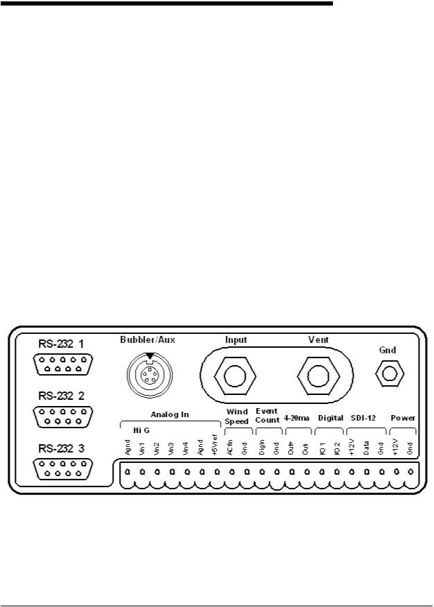
Figure 2-1A shows the wiring panel and illustrates the physical input and output features of the XL™ Series models H-350XL™, H-500XL™ and the H-510XL™ and briefly describes their purposes. Figure 2-1B shows the same wiring panel but for the H-522 and the H-522Plus. These diagrams will help show where you should make connections to your XL™ Series data logger / DCP.
Figure 2-1A Models H-350XL™/H-500XL™/H-510XL™ Front Panel Description
 XL™ Series
Hardware Options and Installation 2-1
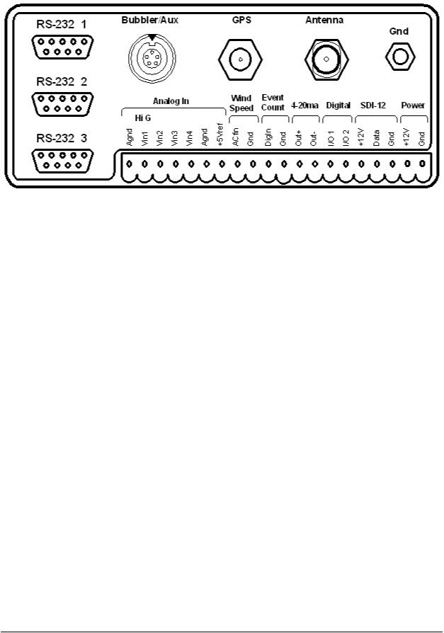
Figure 4-1B Models H-522/H-522+ Front Panel Description
2.2.1 Earth Ground Lug
Run a heavy gauge (14awg) wire from the GND lug of the XL™ to the Earth ground of the instrument shelter. If there is no Earth ground, one must be installed. This is most important in the protection of your electronic equipment. It insures the equipment will function properly. (PROPER GROUNDING IS A MUST!)
2.2.2 Pressure Reference Port (Vent) (H-350XL™ Model only)
In order to make accurate readings, the H-350XL unit must have a way to measure the atmospheric pressure. This port provides that function. The user never has to make connections to, or service this port.
Note: Model H-500XL™ and H-510XL™ only uses this location to secure the wiring panel to the main box using a large hex bolt.
2.2.3 Pressure Port (Input) (H-350XL™ Model only)
This is the pressurized line input port. The user will connect this line to the H-355 bubbler system or to the conoflow system. Make sure the pressure on this line does not exceed the limits of the sensor. The pressure range is listed on the serial number label on the side of the H-350XL.
Note: Model H-500XL™ and H-510XL™ only uses this location to secure the wiring panel to the main box using a large hex bolt.
2-2 Hardware Options and Installation
 XL™ Series

2.2.4 GOES Antenna Output (Model H-522 and H-522Plus only)
This is the GOES antenna connector and uses an N-Type connector. The user will connect the GOES antenna cable to this connector.
Note: Always connect an antenna or a dummy load to this connector when testing the integrated GOES radio.
2.2.5 GPS Antenna connector (Model H-522 and H-522Plus only)
This is the GPS antenna connector. The user will connect the GPS antenna cable to this connector.
When using the H-522 or the H-522Plus the GPS receiver will be built into the GOES HDR radio. The H-522 and H-522Plus units shipping at this time have an Omnisat GOES radio from Signal Engineering built into them. The GPS receiver will turn on and try to acquire the time when power is applied to the unit. It will stay on until the time is acquired. Once the time is acquired the GPS receiver will turn off and schedule the next update to happen in 25 hours and 15 minutes. This non repetitive time prevents the GPS receiver from continually failing due to some external repeated condition. When the GPS receiver turns on to re-sync the time clock it will try to do so for 30 minutes before giving up and waiting for the next day. If it misses a single time sync the GOES radio will still transmit. The GOES radio will stop transmitting if seven consecutive GPS time syncs have been missed. On the seventh time sync attempt the GPS receiver will not power down after 30 minutes but will stay on trying to re-sync the time clock and will only power down after it is successful.
When an Omnisat GOES radio is used externally with other XL Series data loggers the same functionality will exist. This will be discussed in a later chapter.
 XL™ Series
Hardware Options and Installation 2-3

2.2.3.1 Sample Installation for the Conoflow System (H-350XL only)
Figure 2-2 shows a typical H-350XL™ installation for water depth measurement using the Conoflow gas purge system. To install the H-350XL™, secure it to the wall of the instrument shelter or bench top using the provided mounting hardware. This will prevent it from moving or shifting and pulling on the wires and tubing connected to other equipment. The H-350XL™ should be mounted so moisture and dust will not settle on the main I/O panel. Normally vertically is the best with the main I/O panel facing down and the display keypad facing out.
|
|
DIFFERENTIAL |
|
|
|
REGULATOR |
|
|
|
20 - 30 PSI |
|
H-350XL™ |
FEEDBACK TUBE |
|
|
|
MOUNT |
|
|
|
ON WALL |
|
|
|
TO RIVER |
REGULATOR |
|
|
|
SITE-FEED |
|
|
POWER |
NITROGEN |
|
PRESSURE |
SUPPLY |
||
|
|||
RELIEF VALVE |
|
CYLINDER |
GAS PRESSURE
TO MANOMETER
30 BUBBLES PER MINUTE
GAS PURGE
LINE ORIFICE
Figure 2-2 Conoflow Gas Purge Stream Gauge Installation
2-4 Hardware Options and Installation |
XL™ Series |
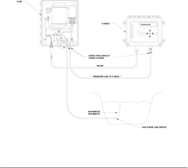
2.2.3.2 Making the Pressure Connection to the H-355 Bubbler System (H-350XL only)
Figure 2-3 illustrates the correct procedure for installing the pressure port fittings between the H-350XL™ and the H-355 Gas Purge System. Chapter 23 goes into more detail on the Gas Purge System. Refer to the manual provided with the H-355 for installation information.
Connect the pressure input line between the H-350XL™ and the H-355 bubbler system using the H-350XL™ Install kit, which includes all the required hardware. You will need a 1/8" NPT male tubing fitting for the pressure input port. It is recommended that you use 1/8" copper tubing. The proper ferrules must be used to insure there are no leaks. The male 1/8" NPT fitting screws into the pressure input port of the H-350XL™ connector panel shown in Figure 2-1. On the bubbler manifold you will need a corresponding tubing fitting. Generally, a 1/4" NPT female to 1/8" tubing fitting is required. The NPT threads of these fittings need a coat of Teflon tape or anaerobic thread dope. This helps in preventing leaks.
Figure 2-3. H-350XL / H-355 Combination Installation
 XL™ Series
Hardware Options and Installation 2-5
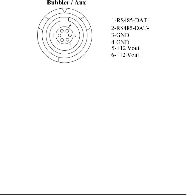
2.2.6 Bubbler / Aux Port
Figure 2-4 is the Bubbler / Aux communication port, which is a 6-pin connector that interfaces with the H-355 Gas Purge System and other WATERLOG® products. The XL™ menu is setup to give the user full control of the H-355 system. As other auxiliary devices are developed to interface with the XL™, they too will be controlled through the XL™ menu system. This port uses RS-485 hardware for communicating with the auxiliary devices. This provides noise immunity and multi drop capability. As other devices are used, the cable will be daisy chained from one device to the next.
Figure 2-4 Bubbler / Auxiliary Output connector pin out
The H-355 is normally used with the H-350XL because it has the built in pressure transducer. However the H-355 may be used with any of the XL series data loggers and an H-350 Lite or similar sensor to collect water level data.
2-6 Hardware Options and Installation
 XL™ Series
2.2.7 RS-232 Ports
The three RS-232 ports are used to connect to a PC, GOES Transmitter, modem, remote display, or other serial equipment for standard serial communications. These ports are configured as a DTE type of device. This means they will plug directly into a modem (a DCE type device), but will require a NULL modem adaptor if connected to a PC (a DTE type device). The NULL modem cable crosses the communication lines allowing two similar devices to communicate. Figure 2-5 shows the pin out for all three ports. See the chapter covering the serial ports for complete information on the port operations.
Figure 2-5 RS-232 Connector
|
SERIAL PORT PIN-OUT |
|
|
PIN |
DIRECTION |
NAME |
|
1 |
Input |
Data Carrier Detect |
(DCD) |
2 |
Input |
Receive Data |
(RD) |
3 |
Output |
Transmit Data |
(TD) |
4 |
Output |
Data Terminal Ready |
(DTR) |
5 |
|
Ground |
(GND) |
6 |
Input |
Data Set Ready |
(DSR) |
7 |
Output |
Request To Send |
(RTS) |
8 |
Input |
Clear To Send |
(CTS) |
9 |
Input |
Ring Indicator |
(RI) |
 XL™ Series
Hardware Options and Installation 2-7
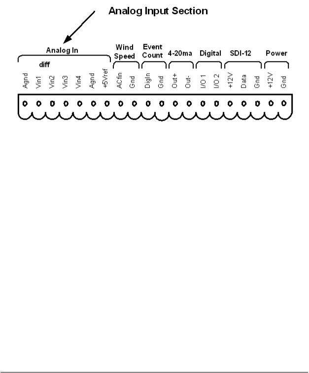
2.2.8 Analog Input Section
The first seven connections on the twenty pin terminal block are used for analog input functions. This includes four analog inputs, two analog grounds and one +5.00 volt excitation connection.
Figure 2-6 Analog Input Section
2.2.8.1 Analog Input Channels
There are four analog input channels labeled Vin1 to Vin4. The standard input range for all channels is 0 to 5 volts, and the optional range is 0 to 500 millivolts. The 500 millivolt range is used for sensors that produce millivolt outputs. For example, some solar radiation sensors have a full scale output of less than 500 millivolts. This type of sensor should be used with the 500 millivolt range. Channels 1 and 2 can also be used in a differential mode. The analog inputs use a 20 bit analog to digital converter.
2.2.8.2 Analog Grounds
There are two analog ground connection points. In order to preserve signal integrity, it is
important to use the analog grounds only for sensors connected to the analog section of the
XL™. The current flowing through an analog sensor is relatively small and normally very stable. This provides stable voltages produced by these sensors. If a digital sensor has its ground connection tied into the analog ground, the currents from the digital sensor will flow through the analog circuitry causing voltage level shifts and noise based on digital switching. There should be sufficient digital ground connection points for the digital sensors.
2-8 Hardware Options and Installation
 XL™ Series
2.2.8.3 Switched +5.00 Volt Reference Excitation
The +5.00 Volt reference output is used for analog sensors requiring a precision reference voltage. The output current source maximum level is 10 milliamps. Exceeding this limit will cause the excitation to possibly sag, and result in possible data errors. The Analog to Digital converter uses this excitation for its reference to provide a ratio-metric relationship for sensors using the excitation. What this means is that if a sensor causes loading to the excitation and drags it down to 4.75 volts for example, then the A/D converter will use the 4.75 volts as its reference, and maintain a full scale input equal to the reduced excitation. To a point this will reduce errors in data when the excitation is used. If the excitation is being loaded down and some analog input channels are not using the excitation, but produce a voltage output on there own, then these inputs will have a much greater error.
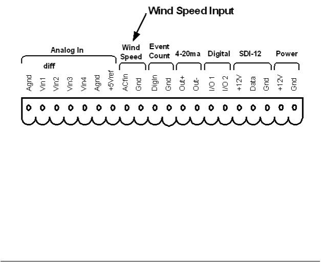
2.2.9 Wind Speed Input (AC Frequency Input)
Pins 8 and 9 of the terminal block provide connection points for a low-level AC signal. Several wind speed sensors produce a low level AC sine wave directly compatible to this input.
Figure 2-7 Wind Speed Input
The wind speed input is a frequency counter capable of accepting low-level signals in the range of ±0.075 volts and greater, however, this input should not be exposed to signals greater than approximately ±5.0 volts. The input signal must be bipolar, that is, the input signal must vary above and below the reference point or ground. Several wind speed sensors use a simple, propeller driven generator that produces an AC signal suitable for this input.
 XL™ Series
Hardware Options and Installation 2-9
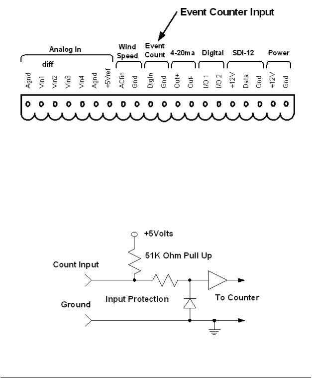
2.2.10 Event Counter Input
Pins 10 and 11 of the terminal block provide connection points for the digital event counter input.
Figure 2-8 Event Counter Input
This input is normally used with a tipping bucket rain gauge. However, it can be used for other counter type of applications also. Transient protection is provided for this input to prevent damage from static discharge or over voltage conditions. This input is pulled high through a 51K Ohm resistor allowing a switch closure to ground to activate the counter. Figure 2-9 shows a simplified circuit for this input.
Figure 2-9 Event Counter Circuit
2-10 Hardware Options and Installation
 XL™ Series
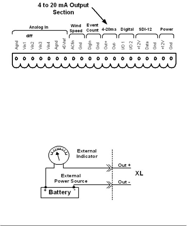
2.2.11 4 to 20 Milliamp Output
Pins 12 and 13 of the terminal block provide connection points for the 4 to 20 milliamp output signal.
Figure 2-10 4 to 20mA Output Section
Several instrumentation applications use sensors that provide an industry standard 4 to 20 milliamp output signal. The XL™ Series data logger / DCP can output a 4 to 20 milliamp signal based on any of its inputs. For example, a user may want to connect a temperature probe to the XL™ and convert the temperature value into a 4 to 20 milliamp output. A temperature probe on Analog Channel 1 that produces a 0 to 5 volt output representing 0 to 100 degrees Celsius could easily be setup to produce a 4 to 20 milliamp output that represents the 0 to 100 degrees. The XL™ does not actually output a 4 to 20 milliamp signal, but rather controls the current in a loop that is powered externally. Figure 2-11 shows a basic connection diagram.
Figure 2-11 Basic 4-20 mA Wiring Configuration
 XL™ Series
Hardware Options and Installation 2-11
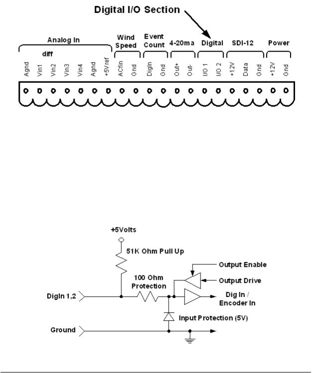
2.2.12 Digital I/O 1 and 2
Pins 14 and 15 of the terminal block provide connection points for the two digital I/O signals. Notice there is no specific ground point for these signals. Use the digital ground pin of the event counter or the SDI-12 ground. Do not use the analog grounds.
Figure 2-12 Digital I/O Section
The two digital I/O signals can be configured independently as inputs or as outputs. In the input mode, the signal has an internal pull up resistor of 51K Ohms. This allows a switch closure to ground to activate the input. It can also be driven using normal logic levels. As an output, the drive capability is limited by a 100 Ohm protection resistor. The output will still be about 4.0 volts with a 10.0 mA or less load. When both pins are configured as inputs, they may be used as a quadrature shaft encoder input. The two digital signals can also be used to simulate a quadrature shaft encoder. Figure 2-13 shows a simplified schematic of how these pins are configured.
Figure 2-13 Basic Digital I/O Schematic
2-12 Hardware Options and Installation
 XL™ Series

2.2.13 SDI-12 Section
Pins 16, 17, and 18 of the terminal block provide connection points for SDI-12 senors and data loggers. The XL™ can be used as both an SDI-12 sensor and as an SDI-12 data logger. In either case these connections are made at the same place. The +12V power connection under the SDI12 section is limited to about one amp so it may be necessary to connect the SDI-12 sensor power line directly to the battery or to main power.
Figure 2-14 SDI-12 Section
If several SDI-12 sensors are to be connected to the XL™, it may be necessary to use an external terminal strip to provide enough connection points.
Figure 2-15 SDI-12 Expanded Connector System
 XL™ Series
Hardware Options and Installation 2-13
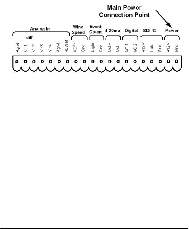
2.2.14 Power Connections
The last two pins at the far right of the terminal block provide the main connection points for system power and ground.
Figure 2-16 Main Power Connection Point
Note: When connecting to or removing the wires from these connection points, it is important to remove the terminal block from the XL™ first, or to have the other end of the wires disconnected from the battery. This helps prevent loose wires with live voltages accidently come in contact with other I/O connection points.
2.3 Testing the Installation
After hooking up the battery, the Power light should begin flashing every 5 to 10 seconds. This indicates that the battery is providing 10 volts or more to the XL™. Press the display On/Off button and the display should come on, indicating the instrument is functional and ready to use.
You will find detailed user setup information and menu options that will allow complete test and verification of all sensor connections and operation in the next two chapters.
2-14 Hardware Options and Installation
 XL™ Series
2.4 Hardware Revision Detection
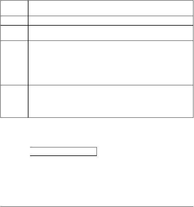
As the XL series data logger has continued to evolve, changes and enhancements involve both the hardware and the firmware. The following list shows some of the major changes to the hardware and how to check as a user what revisions may affect you. For example if your application requires the +12Volt excitation to be switchable, then you must use board revision 3.1 or newer. The firmware can detect the board revision and if an old board is detected, then the menu option to set the +12Volt excitation mode will not be displayed because it has no affect. The table below shows the changes to the hardware over the life of the product.
Board Description
Revision
Rev 2.1 - Original board
Rev 2.2 - New Power down sequence from normal mode to low power mode. This change will not affect the user operation.
Rev 3.1 - New 24 bit A to D converter for the generic analog inputs and stage sensor. The older boards used a 16 bit A to D converter.
-Added differential mode to analog inputs 1 and 2.
-500 millivolt range added to all generic analog inputs.
-The 12 volt excitation is able to be turned on and off.
-Able to use higher baud rates on the serial ports, now up to 115200 baud. The older board would only go to 19200.
Rev 3.3 - A new 16 bit DAC is now used for the 4 to 20 milliamp output option. The older boards used a 12 bit DAC.
- A new internal comm port for H-522 and H-522Plus is used for the built in GOES radio. This allows com port 2 on the H-522 and H-522 Plus to still be used for other purposes.
From the built in keypad / display interface the user can see what board revision is in use. Under the ‘System Status’ menu is a status screen that will show the board revision, for example:
 Hardware Rev = 3.1
 XL™ Series
Hardware Options and Installation 2-15

2-16 Hardware Options and Installation |
XL™ Series |
 Loading...