


XD 9004G
ADKDSWDHD 06/15/2015
XLT Gas Oven & AVI Hood
Installation & Operation Manual
This appliance is for professional use by qualified personnel. This appliance must be installed by qualified persons in accordance with the regulations in force. This appliance must be installed with sufficient ventilation to prevent the occurrence of unacceptable concentrations of substances harmful to health in the room in which it is installed. This appliance needs an unobstructed
flow of fresh air for satisfactory operation & must be installed in a suitably ventilated room in accor- CAUTION dance with current regulations. This appliance should be serviced by qualified personnel at least
every 12 months or sooner if heavy use is expected.
Current versions of this manual, Technical/Rough-In Specifications, Parts & Service Manual, Architectural Drawings, & a list of International Authorized Distributors are available at: www.xltovens.com
For use with the following XLT GAS Oven Versions:
Australia (AE) |
D |
Korea (K) |
D |
Standard (S) |
D |
World (W) |
D |
For use with the following AVI Gas Hood Versions:
Standard (S) |
D |
World (W) |
D |
2000887
XLT Ovens
PO Box 9090
Wichita, Kansas 67277
US: 888-443-2751 FAX: 316-943-2769 INTL: 316-943-2751 WEB: www.xltovens.com
|
|
|
|
|
2 |
WARNING & SAFETY INFORMATION |
|
SAFETY DEPENDS ON YOU
Improper installation, adjustment, alteration, service or maintenance can cause property damage, injury, or death. Read the installation, operating and maintenance instructions thoroughly before installing, using, or servicing this
DANGER equipment.
Post in a prominent location instructions to be followed in the event you smell gas. This information can be obtained by consulting your local gas supplier.
|
FOR YOUR SAFETY |
|
Do not store or use gasoline or other flammable liquids or vapors in |
DANGER |
the vicinity of this or any other appliance. |
|
In the event a gas odor is detected, shut off the gas at the main shutoff valve immediately. Contact your local Gas Company or supplier.
Do not restrict the flow of combustion and/or ventilation air to the unit. Provide adequate clearance for operating, cleaning, maintaining the unit & adequate clearance for operating the gas shutoff valve when the unit is in the installed position.
Keep the area free & clear of combustible material. DO NOT SPRAY AEROSOLS IN THE VICINITY OF THIS APPLIANCE WHILE IT IS IN OPERATION.
Ovens are certified for installation on combustible floors.
Electrical schematics are located inside the control box of the oven and in this manual. Disconnect input power to the unit before performing any maintenance.
This unit requires a ventilation hood. The installation must conform to local codes.
This unit may be operated with either natural gas or liquid petroleum fuel as designated on the nameplate label located on the side of the unit.
This unit must be operated by the same voltage, phase, & frequency of electrical power as designated on the nameplate label located on the side of the unit.
Minimum clearances must be maintained from combustible & non-combustible construction materials.
Follow all local codes when installing this unit.
Follow all local codes to electrically ground the unit.
Appliance is not to be cleaned with high pressure water.
XLT ovens are certified for use in stacks of up to three (3) units of XLT products. Integration of other manufacturer’s products into an oven stack is not recommended, & voids any warranties. XLT Ovens assumes no liability for mixed product applications.
Failure to call XLT Customer Service at 1-888-443-2751 prior to contacting a repair company voids any & all warranties.
PLEASE RETAIN THIS MANUAL FOR FUTURE REFERENCE.
XLT Ovens has spent millions of dollars designing and testing our products as well as developing Installation & Operation Manuals. These manuals are the most complete and easiest to understand in the industry. However, they are worthless if they are not followed.
We have witnessed store operators and building owners lose many thousands of dollars in lost revenue due to incorrect installations. We highly recommend you follow all instructions given in this manual as well as follow best practices in plumbing, electrical, and HVAC building codes.
Technical Support US: 888-443-2751 |
Technical Support INTL: 316-943-2751 |
|
|
|
|
|
|
WARNING & SAFETY INFORMATION |
3 |
Definitions & Symbols
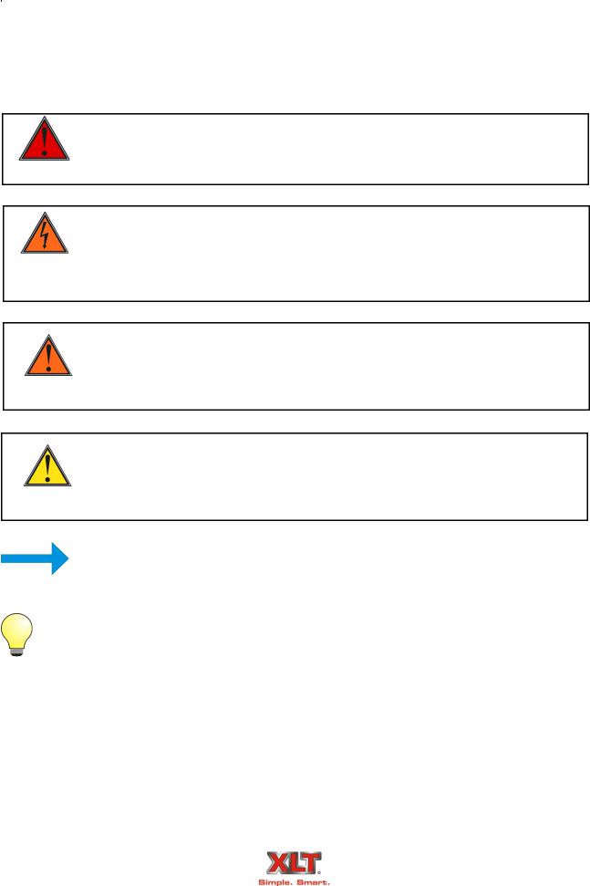
A safety instruction (message) includes a “Safety Alert Symbol” & a signal word or phrase such as DANGER, WARNING or CAUTION. Each signal word has the following meaning:
Indicates a potentially hazardous situation that, if not avoided, can result in serious
injury or death.
DANGER
This symbol indicates high voltage. It calls your attention to items or operations that could be dangerous to you & other persons operating this equipment. Read the
HIGH message & follow the instructions carefully.
VOLTAGE
Indicates a potentially hazardous situation, that if not avoided, can result in cuts or being crushed. It calls your attention to items or operations that could be dangerous
WARNING to you & other persons operating this equipment.
Indicates a potentially hazardous situation, that if not avoided, can result in minor to moderate injury or serious damage to the product. The situation described in the
CAUTION may, if not avoided, lead to serious results. Important safety measures CAUTION are described in CAUTION (as well as WARNING), so be sure to observe them.
|
|
Notes indicates an area or subject of special merit, emphasizing either the product’s |
NOTE |
capability or common errors in operation or maintenance. |
|
|
||
|
Tips give a special instruction that can save time or provide other benefits while installing |
|
|
or using the product. The tip calls attention to an idea that may not be obvious to first-time |
|
TIP |
users of the product. |
|
|
|
|
Technical Support US: 888-443-2751 |
Technical Support INTL: 316-943-2751 |
|
|
|
|

|
Warranty – US and Canada |
Rev D |
Approval Date: 10/28/2013 |
XLT warrants gas ovens manufactured after April 1, 2009 and all electric ovens manufactured after April 1, 2011 to be free from any defect in material and workmanship under normal use for five (5) years from the date of original purchase by the end user, and further warrants main fan blades, conveyor shafts, and conveyor bearings for ten (10) years. XLT further warrants all ovens to be free from rust for ten (10) years from the date the equipment is originally purchased. XLT warrants AVI hoods to be free from any defect in material and workmanship under normal use for two (2) years from the date of original purchase by the end user purchaser. In the event of a part failure, XLT will furnish a replacement part and pay for all labor associated with the replacement of the part. If upon inspection XLT determines that the part is not defective, all incurred cost will be the responsibility of the end user purchaser. This warranty is extended to the original end user purchaser and is not transferable without prior written consent of XLT. Damages are limited to the original purchase price.
DUTIES OF THE OWNER:
The owner must inspect the equipment and crates at time of receipt. Damage during shipment is to be immediately reported to the carrier and also to XLT
The equipment must be installed and operated in accordance with the written instructions furnished with the unit
This warranty shall not excuse the owner from properly maintaining the equipment in accordance with the written instructions furnished with the unit
A copy of the “Initial Start-Up Checklist” must be filled out and returned to XLT when the unit is initially installed, and/or when the unit is removed and installed in another location
The gas, electric, and HVAC utilities must be connected to the oven and installed by locally licensed contractors
Failure to contact XLT Ovens prior to contacting a repair company for warranty work voids any and all warranties
WHAT IS NOT COVERED:
Freight damage
Overtime charges
Any part that becomes defective because of utility services (power surges, high or low voltages, high or low gas pressure or volume, contaminated fuel, or improper utility connections)
Any part that becomes defective because of moisture and/or other contaminants
Conveyor belts
Filters
Exhaust Fans
Light Bulbs
Normal maintenance or adjustments
This warranty shall not apply if the equipment or any part is damaged as a result of accident, casualty, alteration, misuse, abuse, improper cleaning, improper installation, improper operation, natural disasters, or man-made disasters
CLAIMS HANDLED AS FOLLOWS:
Should any such defect be discovered, XLT must be notified. Upon notification, XLT will arrange for necessary repairs to be made by an authorized service agent. Denial of services upon the arrival of an authorized service agent will release XLT of any and all warranty obligations.
7761 W Kellogg Drive 67209-2003 - PO Box 9090 67277-0090 - Wichita, Kansas Voice (316) 943-2751 - (888) 443-2751 - Fax (316) 943-2769 www.xltovens.com

|
Warranty – International |
Rev F |
Approval Date: 07/01/2014 |
When purchased through an Authorized International Distributor, XLT warrants its products manufactured after July 1, 2014 to be free from any defect in material and workmanship under normal use. The Authorized International Distributor will repair XLT products during the warranty period. This warranty is extended to the original end user purchaser and is not transferable without prior written consent of the Authorized International Distributor. Damages are limited to the original purchase price. Products purchased by any other means other than an Authorized International Distributor will have no warranty. This warranty applies to areas outside the 50 United States of America.
DUTIES OF THE OWNER:
The owner must inspect the equipment and crates at time of receipt. Damage during shipment is to be immediately reported to the carrier and also to the Authorized International Distributor.
The equipment must be operated in accordance with the written instructions furnished with the unit.
This warranty is not valid unless equipment is installed, started, and demonstrated under the supervision of the Authorized International Distributor.
This warranty shall not excuse the owner from properly maintaining the equipment in accordance with the written instructions furnished with the unit.
A copy of the “Initial Start-Up Checklist” must be filled out and returned to the Authorized International
Distributor when the unit is initially installed, and/or when the unit is removed and installed in another location.
The gas, electric, and HVAC utilities must be connected to the equipment and installed by locally licensed contractors.
The Authorized International Distributor must be contacted for service. Failure to contact the Authorized International Distributor prior to contacting a repair company for warranty work voids any and all warranties.
WHAT IS COVERED (Subject to local market conditions):
2 year labor – Extensions may be available and charges may apply
5 year parts – Extensions may be available and charges may apply
5 years parts and labor on: oven fan blade, structural welds, conveyor shafts, conveyor bearings, rusted materials in ovens
WHAT IS NOT COVERED (Subject to local market conditions):
Freight damage
Any part that becomes defective because of utility services (power surges, high or low voltages, high or low gas pressure or volume, contaminated fuel, or improper utility connections)
Any part that becomes defective because of moisture and/or other contaminants
Conveyor belts
Filters
Exhaust fans
Light bulbs
Rusted materials in hoods
Normal maintenance or adjustments
This warranty shall not apply if the equipment or any part is damaged as a result of accident, casualty, alteration, misuse, abuse, improper cleaning, use of caustic/acidic chemicals, improper installation, improper operation, natural disasters, or man-made disasters
CLAIMS HANDLED AS FOLLOWS:
Should any such defect be discovered, the Authorized International Distributor must be notified. Upon notification, the Authorized International Distributor will arrange for necessary repairs.
7761 W Kellogg Drive 67209-2003 - PO Box 9090 67277-0090 - Wichita, Kansas Voice (316) 943-2751 - (888) 443-2751 - Fax (316) 943-2769 www.xltovens.com
|
|
|
|
|
6 |
RECEIVING & INSPECTION |
|
|
|
|
|
NOTIFY CARRIER OF DAMAGE AT ONCE
Upon receiving of all goods shipped by a Common Carrier, check for any exterior damage that may indicate interior damage. If conditions permit, open all crates & do a full inspection for any damage while the delivery driver is still there. If there is damage, please note on the delivery receipt & call the carrier to make a freight damage claim within 24 hours of receipt. Failure to make a damage claim within the first 24 hours may void the opportunity to have the claim resolved.
XLT Ovens wants you to be totally satisfied with every aspect of owning & using your oven & hood. Your feedback, both positive & negative, is very important to us as it helps us understand how to improve our products & our company. Our goal is to provide you with equipment that we are proud to build & you will be proud to own.
To receive technical support for the oven or hood you purchased, XLT has qualified customer service personnel that can provide assistance on any type of XLT oven problem you may experience. Customer Service is available 24/7/365 or visit www.xltovens.com.
Installation of all gas appliances & ventilation exhaust hoods should only be performed by a qualified professional who has read & understands these instructions & is familiar with proper safety precautions. Read this manual thoroughly before in-
DANGER stalling or servicing this equipment.
Save this Manual
This document is the property of the owner of this equipment.
XLT Ovens reserves the right to make changes in design & specifications, and/or make additions to or improvements to its product without imposing any obligations upon itself to install them in products previously manufactured.
All Right Hand & Left Hand designations in this manual are from the point of view as if standing directly in front of the glass sandwich door.
Revision History Table
Revision |
Comments |
Date |
|
|
|
F |
Changed Oven Description Table on Page 8. |
04/20/2015 |
|
|
|
G |
Removed All 3270 and 3870 Single Burner Information |
06/15/2015 |
|
|
|
Technical Support US: 888-443-2751 |
Technical Support INTL: 316-943-2751 |
|
|
|
|

TABLE OF CONTENTS |
7 |
Warning & Safety Information..................................................................................................... |
2 |
Warranty....................................................................................................................................... |
4 |
Oven Description......................................................................................................................... |
8 |
Oven Dimensions & Weights..................................................................................................... |
10 |
Oven Gas Requirements ............................................................................................................. |
12 |
Oven Electrical Requirements.................................................................................................... |
18 |
Oven Only Rough-In Specifications .......................................................................................... |
19 |
Oven Assembly .......................................................................................................................... |
20 |
Oven Installation ........................................................................................................................ |
26 |
Oven Fire Suppression ............................................................................................................... |
27 |
Oven Ventilation Requirements & Guidelines........................................................................... |
29 |
Oven Initial Start-Up .................................................................................................................. |
30 |
Oven Operation .......................................................................................................................... |
31 |
Oven Operator Controls ............................................................................................................. |
32 |
Oven Cleaning............................................................................................................................ |
33 |
Oven Maintenance...................................................................................................................... |
37 |
Oven Troubleshooting................................................................................................................ |
38 |
Hood Description ....................................................................................................................... |
41 |
Hood Dimensions & Weights..................................................................................................... |
42 |
Recommended Exhaust Flow Rates .......................................................................................... |
44 |
Hood Electrical Requirements.................................................................................................... |
46 |
Hood Rough-In Specifications ................................................................................................... |
47 |
Hood Electrical Connections...................................................................................................... |
48 |
Hood Installation ........................................................................................................................ |
62 |
Hood Initial Start-Up.................................................................................................................. |
81 |
Hood Operator Controls ............................................................................................................. |
82 |
Hood Valance Kit ....................................................................................................................... |
83 |
Hood Duct Wrap Kit .................................................................................................................. |
86 |
Hood Cleaning............................................................................................................................ |
87 |
Hood Troubleshooting................................................................................................................ |
88 |
Electrical Schematics ................................................................................................................. |
89 |
Certifications ............................................................................................................................ |
103 |
Oven Start-Up Checklist .......................................................................................................... |
105 |
Hood Start-Up Checklist .......................................................................................................... |
107 |
Technical Support US: 888-443-2751 |
Technical Support INTL: 316-943-2751 |
|
|
|
|

|
|
|
|
|
|
|
|
8 |
|
OVEN DESCRIPTION |
|
||
|
|
This manual covers the following Oven & Hood models: |
|
|||
|
|
|
|
|
|
|
|
|
|
|
|
|
|
|
|
|
|
|
|
|
|
|
|
Ovens |
Hoods |
|
|
|
|
|
X3D-1832-xxxxx |
H3D-1832-xxxxx |
|
|
|
|
|
X3D-2440-xxxxx |
H3D-2440-xxxxx |
|
|
|
|
|
X3D-3240-xxxxx |
H3D-3240-xxxxx |
|
|
|
|
|
X3D-3255-xxxxx |
H3D-3255-xxxxx |
|
|
|
|
|
X3D-3270-xxxxx-2B |
H3D-3270-xxxxx-2B |
|
|
|
|
|
X3D-3855-xxxxx |
H3D-3855-xxxxx |
|
|
|
|
|
X3D-3870-xxxxx-2B |
H3D-3870-xxxxx-2B |
|
|
The first 2 digits of the model number after the dash represent the conveyor width and the last two digits indicate the bake chamber length. The five x’s after those numbers represents the oven and hood configuration number. The 3270-2B & 3870-2B models have two burners, one on each side, & have two control boxes. All other models have only a single burner with a single control box that can be supplied on either end. The ovens may be used in a single, double, or triple oven stack configuration. All ovens are gas-fired & are available in Natural gas or Liquid Petroleum gas models (Electric ovens are also available). All models can be configured for a split belt conveyor.
OVEN DESCRIPTION
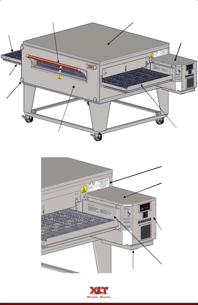
Food product is placed on the stainless steel wire conveyor belt on one side of the oven. The conveyor then transports the food through the bake chamber at a user-controlled speed. This provides repeatable and uniform food cooking. The conveyors can be easily configured to move either left-to-right or right-to-left. A large center sandwich door allows the introduction or removal of food items for cooking at shorter times. Precise temperatures are user adjustable and maintained by a digital control.
An easily removable front panel allows the full cleaning of the oven interior. All exposed oven surfaces both exterior and interior are stainless steel. The conveyor is a one piece design and is removed from the side which has the control box. No tools are required for disassembly and cleaning of the conveyor or oven interior. The oven itself is mounted on lockable swivel casters for easy moving and maintenance.
Accessories such as extended conveyor shelves, base shelves, extended fronts, fire suppression components, and perforated crumb trays are available from XLT. In addition, moving equipment such as carts and lifting jacks are available to help install and move ovens. Please contact XLT Ovens or your Authorized Distributor for more information.
Technical Support US: 888-443-2751 |
Technical Support INTL: 316-943-2751 |
|
|
|
|
|
|
OVEN DESCRIPTION |
9 |
Sandwich Door
Conveyor
Crumb Tray
Front Panel
Knob
Front Panel
Technical Support US: 888-443-2751
Oven Lid
Control Box
Product Stop
 Locking
Swivel Caster
Data Plate
Control Box Lid
 Control Switch
Control Panel
Chain Guard
Document Tray
Technical Support INTL: 316-943-2751
|
|
|
|
|
10 |
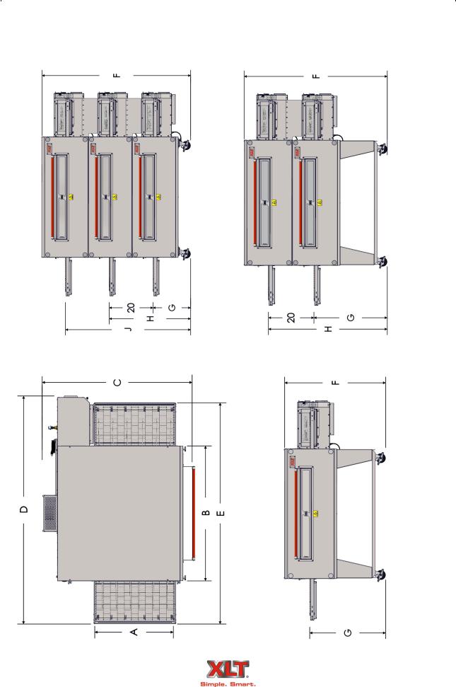
OVEN DIMENSIONS & WEIGHTS |
|
Technical Support US: 888-443-2751 |
Technical Support INTL: 316-943-2751 |
|
|
|
|
|
|
|
|
|
|
|
|
|
|
|
|
|
|
|
|
|
|
|
|
|
|
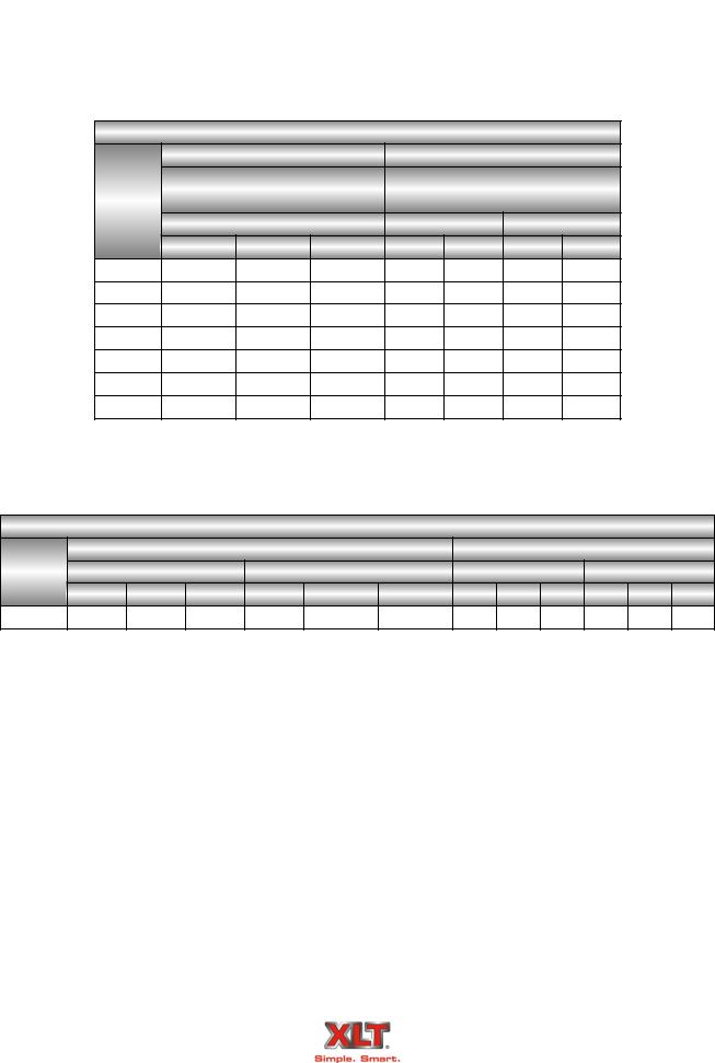
OVEN DIMENSIONS & WEIGHTS |
|
11 |
|
||||||||
|
|
|
|
|
|
|
|
|
|
|
|
|
|
|
|
|
|
|
|
SINGLE |
A |
B |
C |
|
D |
E |
F |
G |
H |
J |
OVEN |
CRATED |
|
|
|
|
OVEN |
|
WEIGHT |
WEIGHT |
|
|||||||||
|
|
|
|
|
|
|
|
|
|
|
|
|
|
|||
|
|
|
1832 |
18 |
32 |
48 3/8 |
|
70 1/4 |
67 1/4 |
42 3/4 |
32 |
N/A |
N/A |
477 |
612 |
|
|
|
|
[457] |
[813] |
[1229] |
|
[1784] |
[1708] |
[1086] |
[813] |
[216] |
[278] |
|
|||
|
|
|
|
|
|
|
|
|||||||||
|
noted. |
|
2440 |
24 |
40 |
54 3/8 |
|
78 1/4 |
75 1/4 |
42 3/4 |
32 |
N/A |
N/A |
543 |
698 |
|
|
|
[610] |
[1016] |
[1381] |
|
[1988] |
[1911] |
[1086] |
[813] |
[246] |
[317] |
|
||||
|
|
|
|
|
||||||||||||
|
|
|
|
|
|
|
|
|||||||||
|
otherwise |
|
3240 |
32 |
40 |
62 3/8 |
|
78 1/4 |
75 1/4 |
42 3/4 |
32 |
N/A |
N/A |
629 |
787 |
|
|
|
[813] |
[1016] |
[1584] |
|
[1988] |
[1911] |
[1086] |
[813] |
[285] |
[357] |
|
||||
|
|
|
|
|
||||||||||||
|
|
|
|
|
|
|
|
|||||||||
|
|
|
3255 |
32 |
55 |
62 3/8 |
|
93 1/4 |
90 1/4 |
42 3/4 |
32 |
N/A |
N/A |
757 |
935 |
|
|
|
|
[813] |
[1397] |
[1584] |
|
[2369] |
[2292] |
[1086] |
[813] |
[343] |
[424] |
|
|||
|
unless |
|
|
|
|
|
|
|||||||||
|
|
3270-2B |
32 |
70 |
62 3/8 |
|
111 |
105 1/4 |
42 3/4 |
32 |
N/A |
N/A |
985 |
1168 |
|
|
|
|
|
|
|
||||||||||||
|
|
|
[813] |
[1778] |
[1584] |
|
[2819] |
[2673] |
[1086] |
[813] |
[447] |
[530] |
|
|||
|
[kilograms] |
|
|
|
|
|
|
|||||||||
|
|
3855 |
38 |
55 |
68 3/8 |
|
93 1/4 |
90 1/4 |
42 3/4 |
32 |
N/A |
N/A |
829 |
1012 |
|
|
|
|
|
|
|
||||||||||||
|
|
|
[965] |
[1397] |
[1737] |
|
[2369] |
[2292] |
[1086] |
[813] |
[376] |
[459] |
|
|||
|
|
|
|
|
|
|
|
|||||||||
|
|
|
3870-2B |
38 |
70 |
68 3/8 |
|
111 |
105 1/4 |
42 3/4 |
32 |
N/A |
N/A |
1077 |
1274 |
|
|
|
|
[965] |
[1778] |
[1737] |
|
[2819] |
[2673] |
[1086] |
[813] |
[489] |
[578] |
|
|||
|
pounds |
|
|
|
|
|
|
|||||||||
|
|
|
|
|
|
|
|
|
|
|
|
|
|
|
|
|
|
|
DOUBLE |
A |
B |
C |
|
D |
E |
F |
G |
H |
J |
OVEN |
CRATED |
|
|
|
|
|
|
|
||||||||||||
|
in |
|
STACK |
|
WEIGHT |
WEIGHT |
|
|||||||||
|
|
|
|
|
|
|
|
|
|
|
|
|
||||
|
weights |
|
1832 |
18 |
32 |
48 3/8 |
|
70 1/4 |
67 1/4 |
62 3/4 |
32 |
52 |
N/A |
863 |
1133 |
|
|
|
|
|
|
||||||||||||
|
|
|
[457] |
[813] |
[1229] |
|
[1784] |
[1708] |
[1594] |
[813] |
[1321] |
[391] |
[514] |
|
||
|
|
|
|
|
|
|
||||||||||
|
All |
|
2440 |
24 |
40 |
54 3/8 |
|
78 1/4 |
75 1/4 |
62 3/4 |
32 |
52 |
N/A |
981 |
1291 |
|
|
|
[610] |
[1016] |
[1381] |
|
[1988] |
[1911] |
[1594] |
[813] |
[1321] |
[445] |
[586] |
|
|||
|
|
|
|
|
|
|||||||||||
|
noted. |
|
|
|
|
|
||||||||||
|
|
3240 |
32 |
40 |
62 3/8 |
|
78 1/4 |
75 1/4 |
62 3/4 |
32 |
52 |
N/A |
1142 |
1458 |
|
|
|
|
|
|
|
||||||||||||
|
|
|
[813] |
[1016] |
[1584] |
|
[1988] |
[1911] |
[1594] |
[813] |
[1321] |
[518] |
[661] |
|
||
|
|
|
|
|
|
|
||||||||||
|
otherwise |
|
3270-2B |
32 |
55 |
62 3/8 |
|
93 1/4 |
90 1/4 |
62 3/4 |
32 |
52 |
N/A |
1380 |
1736 |
|
|
|
|
|
|
|
|
|
|
|
|
|
|
|
|||
|
|
|
3255 |
[813] |
[1397] |
[1584] |
|
[2369] |
[2292] |
[1594] |
[813] |
[1321] |
N/A |
[626] |
[787] |
|
|
|
|
|
|
|
|
||||||||||
|
|
|
|
32 |
70 |
62 3/8 |
|
111 |
105 1/4 |
62 3/4 |
32 |
52 |
|
1817 |
2201 |
|
|
unless |
|
|
[813] |
[1778] |
[1584] |
|
[2819] |
[2673] |
[1594] |
[813] |
[1321] |
|
[824] |
[998] |
|
|
|
3855 |
38 |
55 |
68 3/8 |
|
93 1/4 |
90 1/4 |
62 3/4 |
32 |
52 |
N/A |
1513 |
1879 |
|
|
|
|
|
|
|
|
|
||||||||||
|
[6], |
|
|
[965] |
[1397] |
[1737] |
|
[2369] |
[2292] |
[1594] |
[813] |
[1321] |
|
[686] |
[852] |
|
|
|
3870-2B |
38 |
70 |
68 3/8 |
|
111 |
105 1/4 |
62 3/4 |
32 |
52 |
N/A |
1984 |
2378 |
|
|
|
1/4 |
|
|
|
||||||||||||
|
|
[965] |
[1778] |
[1737] |
|
[2819] |
[2673] |
[1594] |
[813] |
[1321] |
[900] |
[1079] |
|
|||
|
|
|
|
|
|
|||||||||||
|
± |
|
|
|
|
|
|
|
|
|
|
|
|
|
|
|
|
[millimeters], |
|
|
|
|
|
|
|
|
|
|
|
|
|
|
|
|
|
|
[457] |
[813] |
[1229] |
|
[1784] |
[1708] |
[1721] |
[432] |
[940] |
[1448] |
[552] |
[735] |
|
|
|
|
|
TRIPLE |
A |
B |
C |
|
D |
E |
F |
G |
H |
J |
OVEN |
CRATED |
|
|
|
|
STACK |
|
|
|
|
|
|
|
|
|
|
WEIGHT |
WEIGHT |
|
|
|
|
1832 |
18 |
32 |
48 3/8 |
|
70 1/4 |
67 1/4 |
67 3/4 |
17 |
37 |
57 |
1216 |
1621 |
|
|
|
|
|
|
|
|
|
|
|
|
|
|
|
|
|
|
|
inchesin |
|
|
|
|
|
|
|
|
|
|
|
|
|
|
|
|
|
|
32 |
40 |
62 3/8 |
|
78 1/4 |
75 1/4 |
67 3/4 |
17 |
37 |
57 |
1617 |
2091 |
|
|
|
|
|
2440 |
24 |
40 |
54 3/8 |
|
78 1/4 |
75 1/4 |
67 3/4 |
17 |
37 |
57 |
1386 |
1851 |
|
|
|
|
[610] |
[1016] |
[1381] |
|
[1988] |
[1911] |
[1721] |
[432] |
[940] |
[1448] |
[629] |
[840] |
|
|
|
|
|
|
|
|
|||||||||||
|
dimensions |
|
3240 |
[813] |
[1016] |
[1584] |
|
[1988] |
[1911] |
[1721] |
[432] |
[940] |
[1448] |
[733] |
[948] |
|
|
|
|
|
|
||||||||||||
|
|
|
32 |
70 |
62 3/8 |
|
111 |
105 1/4 |
67 3/4 |
17 |
37 |
57 |
2610 |
3186 |
|
|
|
|
|
3255 |
32 |
55 |
62 3/8 |
|
93 1/4 |
90 1/4 |
67 3/4 |
17 |
37 |
57 |
1964 |
2498 |
|
|
|
|
[813] |
[1397] |
[1584] |
|
[2369] |
[2292] |
[1721] |
[433] |
[941] |
[1448] |
[891] |
[1133] |
|
|
|
|
|
|
|
|
|||||||||||
|
All |
|
3270-2B |
[813] |
[1778] |
[1584] |
|
[2819] |
[2673] |
[1721] |
[433] |
[941] |
[1448] |
[1184] |
[1445] |
|
|
|
|
|
|
||||||||||||
|
NOTE: |
|
3855 |
38 |
55 |
68 3/8 |
|
93 1/4 |
90 1/4 |
67 3/4 |
17 |
37 |
57 |
2156 |
2705 |
|
|
|
[965] |
[1397] |
[1737] |
|
[2369] |
[2292] |
[1721] |
[433] |
[941] |
[1448] |
[978] |
[1227] |
|
||
|
|
|
|
|
||||||||||||
|
|
|
|
|
|
|||||||||||
|
|
|
3870-2B |
38 |
70 |
68 3/8 |
|
111 |
105 1/4 |
67 3/4 |
17 |
37 |
57 |
2846 |
3437 |
|
|
|
|
[965] |
[1778] |
[1737] |
|
[2819] |
[2673] |
[1721] |
[433] |
[941] |
[1448] |
[1291] |
[1559] |
|
|
|
|
|
|
|
|
|||||||||||
|
|
Technical Support US: 888-443-2751 |
|
|
|
Technical Support INTL: 316-943-2751 |
|
|||||||||
|
|
|
|
|
|
|
|
|
|
|
|
|
|
|
|
|
|
|
|
|
|
|
|
|
|
|
|
|
|
|
|
|
|
|
|
|
|
|
12 |
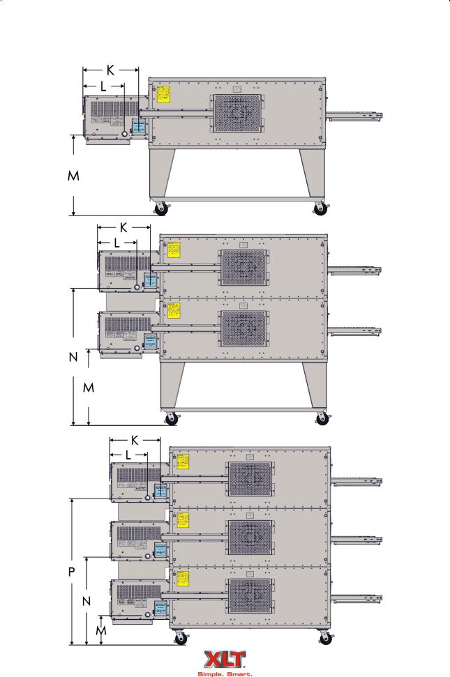
OVEN GAS REQUIREMENTS |
|
GAS AND ELECTRICAL INLET DIMENSIONS WORLD & AUSTRALIA
Technical Support US: 888-443-2751 |
Technical Support INTL: 316-943-2751 |
|
|
|
|

|
|
|
|
|
|
|
|
|
|
|
|
|
|
|
OVEN GAS REQUIREMENTS |
13 |
|||||||||
|
|
|
|
|
|
|
|
|
|
|
|
|
|
|
|
|
SINGLE |
K |
L |
M |
|
N |
P |
|
|
|
|
|
|
OVEN |
|
|
|
|||||
|
|
|
|
|
|
|
|
|
|
|
|
|
|
noted. |
|
|
1832 |
18.25 |
13 |
25 1/2 |
|
- |
- |
|
|
|
|
|
[464] |
[330] |
[648] |
|
- |
- |
|
|
||
|
|
|
|
|
|
|
||||||
|
|
|
|
|
|
|
|
|||||
|
otherwise |
|
|
2440 |
18.25 |
13 |
25 1/2 |
|
- |
- |
|
|
|
|
|
[464] |
[330] |
[648] |
|
- |
- |
|
|
||
|
|
|
|
|
|
|
||||||
|
|
|
|
|
|
|
|
|||||
|
|
|
|
3240 |
18.25 |
13 |
25 1/2 |
|
- |
- |
|
|
|
|
|
|
[464] |
[330] |
[648] |
|
- |
- |
|
|
|
|
unless |
|
|
|
|
|
|
|||||
|
|
|
3255 |
18.25 |
13 |
25 1/2 |
|
- |
- |
|
|
|
|
|
|
|
|
|
|
||||||
|
|
|
|
[464] |
[330] |
[648] |
|
- |
- |
|
|
|
|
[kilograms] |
|
|
|
|
|
|
|||||
|
|
|
3270-2B |
18.25 |
13 |
25 1/2 |
|
- |
- |
|
|
|
|
|
|
|
|
|
|
||||||
|
|
|
|
[464] |
[330] |
[648] |
|
- |
- |
|
|
|
|
|
|
|
|
|
|
|
|||||
|
|
|
|
3855 |
18.25 |
13 |
25 1/2 |
|
- |
- |
|
|
|
|
|
|
[464] |
[330] |
[648] |
|
- |
- |
|
|
|
|
poundsin |
|
|
|
|
|
|
|||||
|
|
|
3870-2B |
18.25 |
13 |
25 1/2 |
|
- |
- |
|
|
|
|
|
|
|
|
|
|
||||||
|
|
|
|
[464] |
[330] |
[648] |
|
- |
- |
|
|
|
|
|
|
|
|
|
|
|
|||||
|
weights |
|
|
|
|
|
|
|
|
|
|
|
|
|
|
DOUBLE |
K |
L |
M |
|
N |
P |
|
|
|
|
|
|
|
|
|
|
||||||
|
|
|
|
STACK |
|
|
|
|||||
|
|
|
|
|
|
|
|
|
|
|
|
|
|
All |
|
|
1832 |
18.25 |
13 |
25 1/2 |
|
45 1/2 |
- |
|
|
|
|
|
[464] |
[330] |
[648] |
|
[1156] |
- |
|
|
||
|
|
|
|
|
|
|
||||||
|
noted. |
|
|
2440 |
18.25 |
13 |
25 1/2 |
|
45 1/2 |
- |
|
|
|
|
|
|
|
|
|
||||||
|
|
|
|
[464] |
[330] |
[648] |
|
[1156] |
- |
|
|
|
|
|
|
|
|
|
|
|
|||||
|
otherwise |
|
|
3255 |
18.25 |
13 |
25 1/2 |
|
45 1/2 |
- |
|
|
|
|
|
|
3240 |
[464] |
[330] |
[648] |
|
[1156] |
- |
|
|
|
|
|
|
|
|
|
|
|||||
|
|
|
|
|
18.25 |
13 |
25 1/2 |
|
45 1/2 |
- |
|
|
|
unless |
|
|
|
[464] |
[330] |
[648] |
|
[1156] |
- |
|
|
|
|
|
3270-2B |
18.25 |
13 |
25 1/2 |
|
45 1/2 |
- |
|
|
|
|
|
|
|
|
|
|
||||||
|
|
|
|
[464] |
[330] |
[648] |
|
[1156] |
- |
|
|
|
|
[6], |
|
|
|
|
|
|
|||||
|
|
|
3855 |
18.25 |
13 |
25 1/2 |
|
45 1/2 |
- |
|
|
|
|
1/4 |
|
|
[464] |
[330] |
[648] |
|
[1156] |
- |
|
|
|
|
|
|
|
|
|
|
||||||
|
± |
|
|
|
18.25 |
13 |
25 1/2 |
|
45 1/2 |
- |
|
|
|
[millimeters], |
|
|
3870-2B |
[464] |
[330] |
[648] |
|
[1156] |
- |
|
|
|
|
|
STACK |
|
|
|
||||||
|
|
|
|
|
|
|
|
|||||
|
|
|
|
|
|
|
|
|
|
|
|
|
|
|
|
|
TRIPLE |
K |
L |
M |
|
N |
P |
|
|
|
|
|
|
|
|
|
|
|||||
|
inches |
|
|
|
|
|
|
|
|
|
|
|
|
|
|
1832 |
18.25 |
13 |
10 1/4 |
|
35 1/4 |
55 1/4 |
|
|
|
|
|
|
[464] |
[330] |
[260] |
|
[895] |
[1403] |
|
|
||
|
|
|
|
|
|
|
||||||
|
|
|
|
|
|
|
|
|||||
|
in |
|
|
2440 |
18.25 |
13 |
10 1/4 |
|
35 1/4 |
55 1/4 |
|
|
|
|
|
|
|
|
|
|
|
|
|
||
|
dimensions |
|
|
[464] |
[330] |
[260] |
|
[895] |
[1403] |
|
|
|
|
|
|
|
|
|
|
||||||
|
|
|
|
18.25 |
13 |
10 1/4 |
|
35 1/4 |
55 1/4 |
|
|
|
|
|
|
|
3240 |
18.25 |
13 |
10 1/4 |
|
35 1/4 |
55 1/4 |
|
|
|
|
|
|
[464] |
[330] |
[260] |
|
[895] |
[1403] |
|
|
|
|
|
|
|
|
|
|
|
|||||
|
All |
|
|
3255 |
[464] |
[330] |
[260] |
|
[895] |
[1403] |
|
|
|
|
|
|
|
|
|
||||||
|
|
|
|
|
|
|
|
|||||
|
NOTE: |
|
|
3270-2B |
18.25 |
13 |
10 1/4 |
|
35 1/4 |
55 1/4 |
|
|
|
|
|
[464] |
[330] |
[260] |
|
[895] |
[1403] |
|
|
||
|
|
|
|
|
|
|
||||||
|
|
|
|
|
|
|
|
|||||
|
|
|
|
3855 |
18.25 |
13 |
10 1/4 |
|
35 1/4 |
55 1/4 |
|
|
|
|
|
|
[464] |
[330] |
[260] |
|
[895] |
[1403] |
|
|
|
|
|
|
|
|
|
|
|
|||||
|
|
|
|
3870-2B |
18.25 |
13 |
10 1/4 |
|
35 1/4 |
55 1/4 |
|
|
|
|
|
|
[464] |
[330] |
[260] |
|
[895] |
[1403] |
|
|
|
|
|
|
|
|
|
|
|
|||||
Technical Support US: 888-443-2751 |
|
|
|
Technical Support INTL: 316-943-2751 |
|
|||||||
|
|
|
|
|
|
|
|
|
|
|
|
|
|
|
|
|
|
|
|
|
|
|
|
|
|
|
|
|
|
|
14 |
OVEN GAS REQUIREMENTS |
|
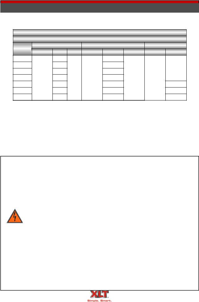
All values shown on this page are per each oven
Gas Oven Heating Values & Orifice Sizes
|
Heating Values |
|
Orifice Sizes |
|
|||
Oven |
Australia, Korea, Standard & |
Australia, Korea, Standard & |
|||||
|
World |
|
|
World |
|
||
Model |
|
|
|
|
|||
|
All Fuels |
|
NAT |
LP |
|
||
|
|
|
|
||||
|
BTU/HR KW/HR MJ/HR Inches MM Inches MM |
||||||
1832 |
47,700 |
14.5 |
50.32 |
0.125 |
3.18 |
0.081 |
2.06 |
2440 |
67,200 |
19 |
70.89 |
0.144 |
3.66 |
0.089 |
2.26 |
3240 |
96,100 |
21.6 |
101.39 |
0.170 |
4.31 |
0.111 |
2.82 |
3255 |
119,900 |
31.95 |
126.5 |
0.191 |
4.82 |
0.116 |
2.95 |
3270-2B |
140,800 |
36.84 |
148.55 |
0.144 |
3.66 |
0.096 |
2.44 |
3855 |
142,200 |
41.64 |
150.02 |
0.209 |
5.31 |
0.125 |
3.18 |
3870-2B |
137,900 |
36.84 |
145.49 |
0.144 |
3.66 |
0.096 |
2.44 |
Gas Oven Fuel Pressure Requirements
Oven |
|
|
Inlet Pressure Range |
|
Manifold Pressure |
|
|||||
|
Natural Gas |
|
LP Gas |
|
Natural Gas |
LP Gas |
|
||||
Models |
|
|
|
|
|||||||
W/C |
mbar |
kPa |
W/C |
mbar |
kPa |
W/C mbar |
kPa |
W/C mbar |
kPa |
||
|
|||||||||||
All |
6-14 |
15-35 |
1.5-3.5 |
11.5-14 |
27.5-35.0 |
2.75-3.50 |
3.5 8.75 |
0.875 |
10 25 |
2.5 |
|
Technical Support US: 888-443-2751 |
Technical Support INTL: 316-943-2751 |
|
|
|
|

|
|
|
|
|
|
|
|
|
|
|
|
|
OVEN GAS REQUIREMENTS |
|
15 |
||||||
|
|
|
|
|
|
|
|
|
|
|
|
|
|
|
|
|
|
World Oven Gas Group |
|
|
|
|
|
|
Natural Gas |
|
|
Propane Gas |
|
|||
|
Gas Group |
I2H |
I2E |
I2E+ |
|
I2L |
I3+ |
I3B/P (30) |
I3P (30/37/50) |
I3B (37) |
|
Inlet pressure (mbar) |
20 |
20 |
20/25 |
|
25 |
28/30/37/50 |
28-30/37/50 |
30/37/50 |
37 |
|
|
|
|
|
|
|
|
|
|
|
|
Number of injectors |
(1) per burner |
|
|
|
|
|
|||
|
|
|
|
|
|
|
|
|
|
|
|
Main burner opening size |
Fixed |
|
|
|
|
|
|
|
|
|
|
|
|
|
|
|||||
|
Ignition |
Electric Direct Spark Igniter |
|
|
|
|||||
|
|
|
|
|
|
|
||||
|
Inlet connection |
BSP 3/4" male thread |
|
|
|
|
||||
|
|
|
|
|
|
|
|
|
|
|
Gas Matrix by Country
Country |
Symbol |
Natural Gas (8.75 mbar manifold) |
LP Gas (25 mbar manifold) |
||||||
I2H |
I2L |
I2E |
I2E+ |
I3B/P |
I3+ |
I3P |
|||
|
|
||||||||
Austria |
AT |
X |
|
|
|
X |
|
|
|
Belgium |
BE |
|
|
|
X |
|
X |
|
|
Cyprus |
CY |
|
|
|
|
X |
X |
X |
|
Czech Republic |
CZ |
X |
|
|
|
X |
|
|
|
Denmark |
DK |
X |
|
|
|
X |
|
|
|
Estonia |
EE |
X |
|
|
|
|
|
|
|
Finland |
FI |
X |
|
|
|
X |
|
|
|
France |
FR |
|
|
|
X |
X |
X |
X |
|
Germany |
DE |
|
|
X |
|
X |
|
X |
|
Greece |
GR |
X |
|
|
|
|
|
|
|
Hungary |
HU |
|
|
|
|
X |
|
X |
|
Iceland |
IS |
|
|
|
|
|
|
|
|
Ireland |
IE |
X |
|
|
|
|
X |
X |
|
Italy |
IT |
X |
|
|
|
|
X |
|
|
Latvia |
LT |
|
|
|
|
X |
|
|
|
Lithuania |
LV |
|
|
|
|
|
|
|
|
Luxembourg |
LU |
|
|
|
|
|
|
|
|
Malta |
MT |
|
|
|
|
X |
|
X |
|
Netherlands |
NL |
|
X |
|
|
X |
|
X |
|
Norway |
NO |
|
|
|
|
X |
|
|
|
Poland |
PL |
|
|
X |
|
|
|
|
|
Portugal |
PT |
X |
|
|
|
|
X |
X |
|
Slovakia |
SK |
|
|
|
|
X |
|
|
|
Slovenia |
SI |
X |
|
|
|
|
|
|
|
Spain |
ES |
X |
|
|
|
|
X |
X |
|
Sweden |
SE |
X |
|
|
|
X |
|
|
|
Switzerland |
CH |
X |
|
|
|
X |
X |
X |
|
United Kingdom |
GB |
X |
|
|
|
|
X |
X |
|
Technical Support US: 888-443-2751 |
|
|
Technical Support INTL: 316-943-2751 |
||||||
|
|
|
|
|
16 |
OVEN GAS REQUIREMENTS |
|
Gas Supply Requirements for Australian, Standard & World Ovens
All installations must conform to local building & mechanical codes.
NOTE
1.The gas supply shall have a gas meter & regulator large enough to handle ALL of the gas appliances, such as the furnace, water heater, & ovens in operation at the same time. Add up all of the Btu/kw/MJ ratings to determine the total load.
2.The gas supply shall have a separate gas meter and gas pressure regulator for each occupant. Installations in multiple occupancy buildings, (strip malls) shall not share gas meters and regulators with other occupants.
3.Gas hose assemblies with quick disconnects for each oven deck will be installed at each valve.
4.A sediment trap shall be installed downstream of the equipment shutoff valve as close to the inlet of the appliance as practical at the time of appliance installation. The sediment trap shall be either a tee fitting with a capped nipple in the bottom outlet as illustrated, and in accordance with ANSI Z223.1-2012 and NFPA 54-2012 National Fuel Gas Code, section 9.6.7.
5.The composition of gases varies greatly from time to time and from place to place. For this reason, the material used for the gas lines shall be steel or malleable iron, not copper. ANSI Z83.11-2006 CSA 1.8-2006 Gas Food Service Equipment states: “Copper tubing or semi rigid tubing with internal copper layering, whether internally tinned or not, shall not be used for conveying gases.” ANSI Z223.1 NFPA 54 National Fuel Gas Code states: “Copper and brass tubing shall not be used if the gas contains more than an average of 0.3 grains of hydrogen sulfide per 100 scf of gas (0,7 mg/100L).”
Do not use Teflon tape on gas line connections as this can possibly cause gas valve malfunction or plugging of orifices from shreds of tape. Use of Teflon tape may af-
CAUTION fect warranty.
Technical Support US: 888-443-2751 |
Technical Support INTL: 316-943-2751 |
|
|
|
|

|
|
OVEN GAS REQUIREMENTS |
17 |
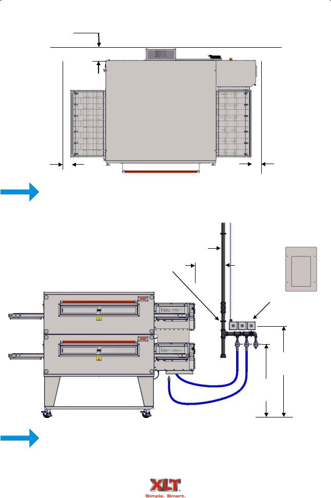
A minimum of a 1 1/2 supply line is required.
2 |
|
Item # |
Description |
Qty |
|
|
7 |
1 |
¾ Manual Gas Valve |
3 |
|
|
|
|
|
|
|
|
|
2 |
1-½ Ball Valve |
1 |
|
|
9 |
|
|
|
|
|
3 |
¾ x 3 Nipple |
3 |
||
|
|
||||
8 |
|
|
|
|
|
6 |
4 |
1-½ Pipe Cap |
1 |
||
|
|||||
|
|
|
|
||
|
5 |
1-½ x 10 Nipple |
2 |
||
|
|
||||
5 |
|
|
|
|
|
10 |
6 |
1-½ x 3 Nipple |
2 |
||
|
|||||
|
3 |
7 |
1-½ x 5 Nipple |
1 |
|
|
|
|
|
||
4 |
8 |
1-½ Tee |
1 |
||
|
|||||
|
|
|
|
||
|
9 |
1-½ x ¾ x 1-½ Reducing Tee |
2 |
||
|
|
||||
|
1 |
|
|
|
|
|
10 |
1-½ x ¾ Reducing Elbow |
1 |
||
|
|
||||
|
|
|
|
|
Gas Supply Testing Requirements
1.The appliance & its individual shutoff valve must be disconnected from the gas supply piping system during any pressure testing of that system at test pressures in excess of 3.5 kPa or ½- psi.
2.The appliance must be isolated from the gas supply piping system by closing its individual manual shutoff valve during any pressure testing of the gas supply piping system at test pressures equal to or less than 3.45 kPa or ½-psi.
Gas Hose Requirements
For Australia, if installing with a flexible hose assembly, the assembly must be certified to AS/NZS 1869, & be Class B or D.
For Standard Ovens, if installing with a flexible gas hose, the installation must comply with either ANSI Z21.69 or CAN/CGA-6.16 & a disconnect device complying with either ANSI Z21.41 or CAN-6.9.
The installation must conform with local building codes, or in the absence of local codes, with the National Fuel Gas Code, ANSI Z223.1, latest version, Natural Gas Installation Code, CAN/ CGA-B149.1, or the Liquid Petroleum Gas Installation Code, CAN/CGA-B149.2, as applicable.
Technical Support US: 888-443-2751 |
Technical Support INTL: 316-943-2751 |
|
|
|
|
18 |
OVEN ELECTRICAL REQUIREMENTS |
|
||||||
|
|
|
All values shown this page are per each oven |
|
|
|||
|
|
|
Gas Oven Electrical Requirements |
|
|
|||
|
|
|
|
Per EACH Oven |
|
|
|
|
Oven |
|
Standard |
Australia & World |
Korea |
||||
Model |
Volts AC Amps |
Hertz Volts AC |
Amps |
Hertz |
Volts AC Watts |
|||
1832 |
|
|
6 |
|
3 |
|
|
|
2440 |
|
|
6 |
|
3 |
|
|
660 |
3240 |
|
|
6 |
220/230/ |
3 |
|
|
|
120 VAC |
|
220 VAC |
|
|||||
3255 |
6 |
50/60 240 VAC |
3 |
50/60 |
|
|||
1Φ |
|
1Φ |
|
|||||
3270-2B |
|
12 |
1Φ |
6 |
|
1320 |
||
|
|
|
|
|||||
3855 |
|
|
6 |
|
3 |
|
|
660 |
3870-2B |
|
|
12 |
|
6 |
|
|
1320 |
FOR EACH OVEN:
A separate 20A circuit breaker must be provided for each oven deck.
Electrical connections must be accessible when the ovens are in the installed position.
Electrical connections must meet all local code requirements.
Electrical Grounding Instructions
Standard Ovens
HIGH
VOLTAGE
This appliance is equipped with a three-prong (grounding) plug for your protection against shock hazard & should be plugged into a properly grounded threeprong receptacle. Do not cut or remove the grounding prong from this plug.
When installed, the appliance must be electrically grounded in accordance with local codes, or in the absence of local codes, with the National Electrical Code, ANSI/NFPA 70, or the Canadian Electrical Code, CSA C22.2, as applicable.
World Ovens
This appliance is equipped with a ground lug for your protection against shock hazard & must be properly grounded.
When installed, the appliance must be electrically grounded in accordance with local codes.
Australian Ovens
This appliance is equipped with a ground lug for your protection against shock hazard & must be properly grounded.
The electrical service must be installed in accordance with AS/NZS 3000 Wiring Rules.
Technical Support US: 888-443-2751 |
Technical Support INTL: 316-943-2751 |
|
|
|
|
|
|
OVEN ONLY ROUGH-IN SPECIFICATIONS |
19 |
|
|
6.00 [152] From back of oven to wall
6.00 [152] |
6.00 [152] |
|
minimum clearance |
|
minimum clearance |
|
|
|
Utilities must be easily accessible when the ovens are in the installed position. Do not
install utilities behind the ovens.
NOTE
 3.00 [76]
Gas Manifold
6.00
[152]
Electrical Supply
48.00
[1219]
42.00
[1067]
All installations must conform to local building and mechanical codes. It is required
NOTE
that the ovens be placed under a ventilation hood to provide exhaust ventilation and adequate air supply.
Technical Support US: 888-443-2751 |
Technical Support INTL: 316-943-2751 |
|
|
|
|
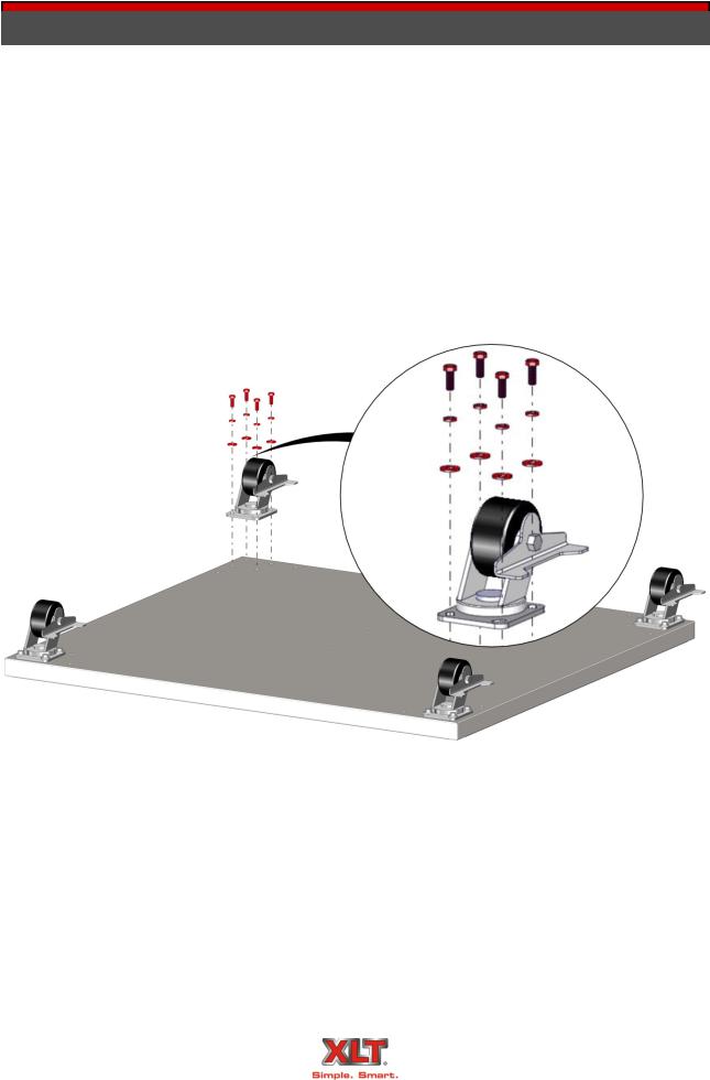
20 OVEN ASSEMBLY
Base Assembly - Triple Stack
Technical Support US: 888-443-2751 |
Technical Support INTL: 316-943-2751 |
|
|
|
|
|
|
OVEN ASSEMBLY |
21 |
Base Assembly - Single & Double Stack
Technical Support US: 888-443-2751 |
Technical Support INTL: 316-943-2751 |
|
|
|
|
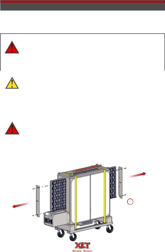
22 OVEN ASSEMBLY
WARNING & SAFETY INFORMATION
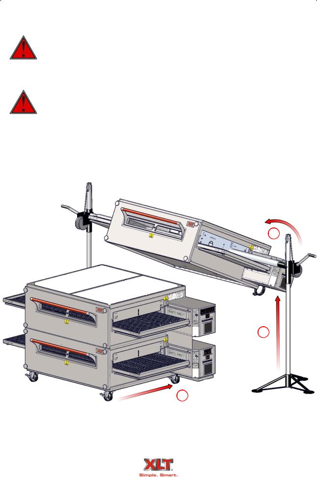
XLT ovens can easily be moved and stacked with the proper lifting equipment. The use of XLT approved lifting equipment is highly recommended. Contact XLT for more information.
These ovens are heavy & can tip or fall causing bodily injury.
NEVER place any part of your body beneath any oven that is suspended by the lifting jacks. A crush hazard exists if the oven falls or slips.
DANGER |
DO NOT place your hands on the lifting jack vertical pole beneath the jack’s |
|
winch. As the jack’s winch descends when you turn the jack handle, a pinch |
||
|
||
|
point is created between the winch & the pole. |
|
|
|
|
|
|
|
|
BE CAREFUL when rolling the oven on the cart, especially when going up or |
|
|
down ramps & over bumps. Leave the straps/banding on until the oven is near |
|
CAUTION |
the assembly area. |
|
|
||
|
|
|
|
|
|
|
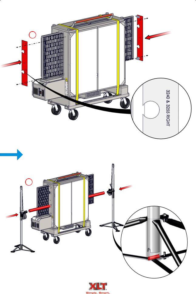
Make sure that the notch on tube of the winch assembly is aligned with the pin |
|
|
in the tripod base as shown. These alignments are important and keep the jack |
|
|
aligned properly. |
|
|
Check for smooth operation. The cable should not be pinched and should pass |
|
|
smoothly over the pulley on top of the pole assembly. |
|
|
Inspect cable prior to each use. |
|
DANGER |
If cable is frayed or shows signs of excessive wear and tear, DO NOT USE until |
|
cable is replaced. |
||
|
||
|
At a minimum replace the cable annually with wire rope that meets or exceeds |
|
|
the jack manufacturer’s specifications. |
|
|
Do not exceed the stated capacity of the jack. |
|
|
|
1
Technical Support US: 888-443-2751 |
Technical Support INTL: 316-943-2751 |
|
|
|
|
|
|
OVEN ASSEMBLY |
23 |
2
The Lifting Pipe hole, marked for the appropriate oven size, must be installed closest
to the control box.
NOTE
3
Technical Support US: 888-443-2751 |
Technical Support INTL: 316-943-2751 |
|
|
|
|
|
|
|
|
|
|
24 |
|
OVEN ASSEMBLY |
|
|
|
|
Stacking the Ovens |
|
|
|
|
|
|
|
|
Failure to engage the Lifting Jacks into the Lifting Pipe properly and completely |
|
|
|
|
will result in damage, injury, or death from a falling oven. |
|
|
|
DANGER |
|
|
|
|
|
|
|
|
|
|
Both jacks should be raised in unison, otherwise they may bind and a dangerous |
|
|
|
|
|
situation will develop. |
|
|
|
Do not put any part of yourself under the oven at any time. |
|
|
|
DANGER |
|
The Oven is top heavy. Be careful. |
|
|
|
|
||
|
|
|
|
|
5
4
6
Technical Support US: 888-443-2751 |
Technical Support INTL: 316-943-2751 |
|
|
|
|

|
|
OVEN ASSEMBLY |
25 |
Stacking the Ovens
Technical Support US: 888-443-2751 |
Technical Support INTL: 316-943-2751 |
|
|
|
|
|
|
|
|
|
26 |
OVEN INSTALLATION |
|
|
|
|
|
Physical Location & Spacing Requirements
These ovens are suitable for installation on either combustible or non-combustible floors, and adjacent to either combustible or non-combustible walls. The motor cover is designed to provide the proper clearance to the back of the oven. The minimum side clearances are 6in. / 150mm, measured from the end of the conveyor.
|
All installations must conform to local building and mechanical codes. |
NOTE |
In Australia, install the restraint cable in accordance with AS 5601. |
|
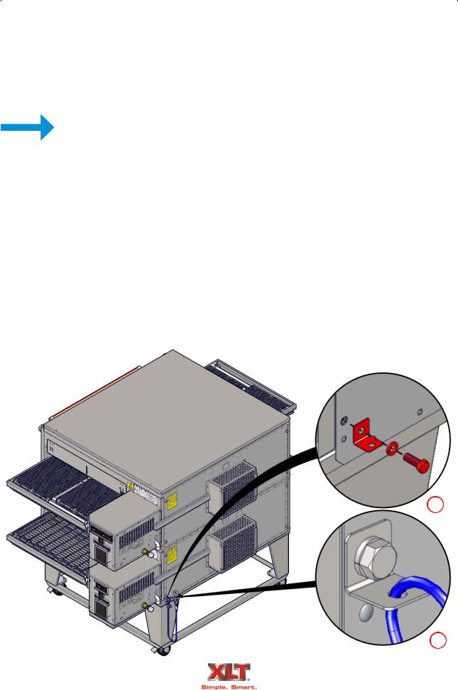
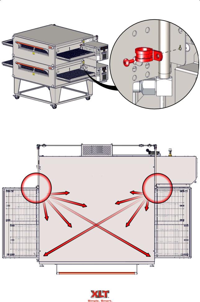
Restraint
Because all ovens are equipped with casters, all installations must be configured with a restraint to limit the movement of the oven without depending on the electric power supply cord or gas hose to limit the oven movement. One (1) restraint kit, which includes one (1) eye bolt, (1) stainless steel clip & a cable, is required for each oven stack, regardless if used on a single, double, or triple configuration. The clip should be installed in the lowest hole of the back wall on the control end of the lowest oven in the stack. The lag eye bolt must be installed into a structural member of a wall or the floor. It is the owner’s responsibility to ensure the restraint is installed correctly.
Upon completion of performing any service or cleaning functions that require removal of the restraint, insure that it is correctly re-attached to the oven.
1
2
Technical Support US: 888-443-2751 |
Technical Support INTL: 316-943-2751 |
|
|
|
|
|
|
OVEN FIRE SUPPRESSION |
27 |
|
|
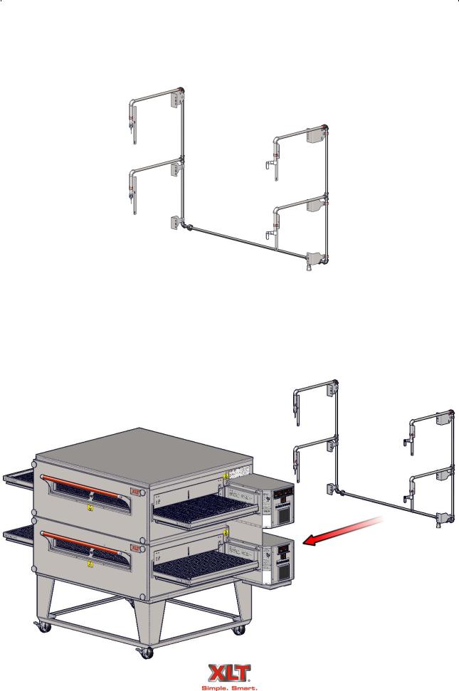
The requirement for fire suppression systems vary by location and the authority having jurisdiction. If you are required to install fire suppression on your oven, a pre-assembled piping kit is available that utilizes pre-existing holes to simplify installation and future service.
This design has been tested and approved to successfully comply with fire suppression codes. It uses only two (2) nozzles per bake chamber, and allows crumb trays, chain guards, and all other accessories to be easily removed. The kit does not interfere with any operations or maintenance.
For fire suppression detailed information see manual XD-9011 Fire Suppression Installation for AVI Hoods and XLT Ovens.
Technical Support US: 888-443-2751 |
Technical Support INTL: 316-943-2751 |
|
|
|
|
|
|
|
|
|
28 |
OVEN FIRE SUPPRESSION |
|
|
|
|
|
Technical Support US: 888-443-2751 |
Technical Support INTL: 316-943-2751 |
|
|
|
|
OVEN VENTILATION REQUIREMENTS & GUIDELINES 29
Ventilation Requirements
A powered ventilation hood is required to remove heat and vapors. Some provision must be made to replenish the amount of air that is extracted from the building. The hood and HVAC installation must meet local building and mechanical codes. Requirements vary throughout the country depending upon location. Proper ventilation is the oven owner’s responsibility. The AVI
Hood system is designed to meet all requirements for XLT ovens and it is our recommendation that this system be used.
Ventilation Guidelines
Obtain information from the authority having jurisdiction to determine the requirements for your installation. Your ventilation hood supplier and HVAC contractor should be contacted to provide guidance. An air balance test is highly recommended, performed by a licensed contractor. A properly engineered and installed ventilation hood and HVAC system will expedite approval, reduce all maintenance costs, and provide a more comfortable working environment. XLT also recommends that the operator switches for the ovens and the operator switch for the exhaust fan be interlocked so that the exhaust fan gets energized whenever the ovens are turned on. For more information, see the following links at xltovens.com:
Kitchen Ventilation Design Guide 1
Kitchen Ventilation Design Guide 2
Kitchen Ventilation Design Guide 3
Kitchen Ventilation Design Guide 4
Ventilation Performance Test
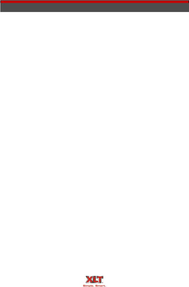
After the oven and ventilation hood have been installed and are operating, a smoke candle can be used to “see” if the heat and vapors are being completely extracted. The test procedure is outlined below:
The oven must be operating at 450º-500ºF / 232º-260ºC.
The conveyor must be turned off.
The ventilation hood exhaust fan must be turned on.
Put a smoke candle in a pan on the conveyor belt at the center of the oven.
Observe the smoke pattern coming out of the oven.
Repeat the smoke candle test for each oven, as well as when all ovens are operating.
The ventilation hood must capture all of the smoke from the oven.
After the exhaust fan has been adjusted to completely capture and contain the heat, there needs to be a corresponding amount of make up air (MUA) introduced into the building to offset the amount of air volume being removed. An air balance test can determine the proper amount of make-up air flow rates.
Technical Support US: 888-443-2751 |
Technical Support INTL: 316-943-2751 |
|
|
|
|

|
|
|
|
|
30 |
OVEN INITIAL START-UP |
|
|
|
|
|
All ovens are tested at the factory for functional operation. Operation is verified and adjustments are made to ensure proper function. However, field conditions are sometimes different than factory conditions. It is necessary to have an authorized service technician verify operation and make field adjustments if needed.
The Oven Initial Start-Up Checklist, found at the end of this manual, must be completed (both sides) at time of installation, signed by the Customer and returned to XLT Ovens and the Authorized Distributor to initiate Warranty Policy.
If the Start-Up Checklist is not filled out completely and returned to XLT Ovens, then the Warranty will not be honored.
Start-up Procedure:
Ensure that all ovens have been installed in accordance with the I&O Manual and that all utilities are connected to the ovens in compliance with local building codes. A copy of the Start-up checklist is located at the end of this manual.
1.Fill out Step 1 on the checklist with all information and print legibly.
2.Place 1 control box in service position and document incoming gas pressure (Refer to P&S manual for gas valve adjustments) If gas pressure is not within XLT specifications contact gas company to adjust.
3.Place all control boxes in service position, remove all blue tags from inside all control boxes and connect switch to wire harness. Start each oven and complete form.
4.With all appliances running, check the dynamic gas pressure. If gas pressure is not within XLT specifications contact gas company to adjust.
5.Complete Start-up checklist with owner signature and return to XLT.
Technical Support US: 888-443-2751 |
Technical Support INTL: 316-943-2751 |
|
|
|
|
 Loading...