


XICOR X76F640XE-2,7, X76F640XE, X76F640X-2,7, X76F640X, X76F640WE-2,7 Datasheet
...
|
|
|
|
|
|
|
|
|
|
|
|
|
|
|
|
|
|
|
|
64K |
X76F640 |
8Kx8+32x8 |
||
Secure SerialFlash
FEATURES
•64-bit Password Security
—Five 64-bit Passwords for Read, Program and Reset
•8192 Byte+32 Byte Password Protected Arrays
—Seperate Read Passwords
—Seperate Write Passwords
—Reset Password
•Programmable Passwords
•Retry Counter Register
—Allows 8 tries before clearing of both arrays
—Password Protected Reset
•32-bit Response to Reset (RST Input)
•32 byte Sector Program
•400kHz Clock Rate
•2 wire Serial Interface
•Low Power CMOS
—2.7 to 5.5V operation
—Standby current Less than 1 A
—Active current less than 3 mA
•High Reliability Endurance:
—100,000 Write Cycles
•Data Retention: 100 years
•Available in:
—8 lead SOIC
—SmartCard Module
DESCRIPTION
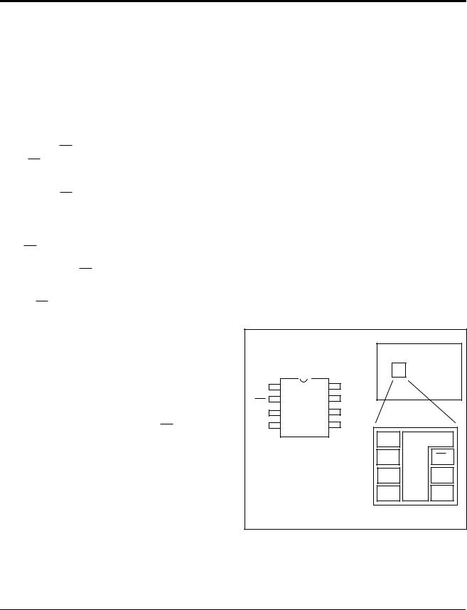
The X76F640 is a Password Access Security Supervisor, containing one 65536-bit Secure SerialFlash array and one 256-bit Secure SerialFlash array. Access to each memory array is controlled by two 64-bit passwords. These passwords protect read and write operations of the memory array. A separate RESET password is used to reset the passwords and clear the memory arrays in the event the read and write passwords are lost.
The X76F640 features a serial interface and software protocol allowing operation on a popular two wire bus. The bus signals are a clock Input (SCL) and a bidirectional data input and output (SDA). Access to the device is controlled through a chip select (CS) input, allowing any number of devices to share the same bus.
The X76F640 also features a synchronous response to reset providing an automatic output of a hard-wired 32-bit data stream conforming to the industry standard for memory cards.
The X76F640 utilizes Xicor’s proprietary Direct WriteTM cell, providing a minimum endurance of 100,000 cycles and a minimum data retention of 100 years.
Functional Diagram |
|
|
CS |
CHIP ENABLE |
8K BYTE |
|
||
SCL |
DATA TRANSFER |
SerialFlash ARRAY |
|
ARRAY 0 |
|
SDA |
ARRAY ACCESS |
(PASSWORD PROTECTED) |
|
||
INTERFACE |
|
|
ENABLE |
|
|
|
|
|
LOGIC |
|
32 BYTE |
|
|
|
|
|
SerialFlash ARRAY |
|
PASSWORD ARRAY |
ARRAY 1 |
|
AND PASSWORD |
(PASSWORD PROTECTED) |
|
|
|
|
VERIFICATION LOGIC |
|
RST |
|
|
|
RESET |
RETRY COUNTER |
|
RESPONSE REGISTER |
|
|
|
7025 FM 01 |
Xicor, Inc. 1994, 1995, 1996 Patents Pending |
1 |
Characteristics subject to change without notice |
7025-1.4 3/24/97 T2/C0/D1 SH |
|
|
|
|
X76F640
PIN DESCRIPTIONS
Serial Clock (SCL)
The SCL input is used to clock all data into and out of the device.
Serial Data (SDA)
SDA is a true three state serial data input/output pin. During a read cycle, data is shifted out on this pin. During a write cycle, data is shifted in on this pin. In all other cases, this pin is in a high impedance state.
Chip Enable (CS)
When CS is high, the X76F640 is deselected and the SDA pin is at high impedance and unless an internal write operation is underway, the X76F640 will be in standby mode. CS low enables the X76F640, placing it in the active mode.
Reset (RST)
RST is a device reset pin. When RST is pulsed high while CS is low the X76F640 will output 32 bits of fixed data which conforms to the standard for “synchronous response to reset”. CS must remain LOW and the part must not be in a write cycle for the response to reset to occur. See Figure 11. If at any time during the response to reset CS goes HIGH, the response to reset will be aborted and the part will return to the standby state. The response to reset is "mask programmable" only!
DEVICE OPERATION
There are two primary modes of operation for the X76F640; Protected READ and protected WRITE. Protected operations must be performed with one of four 8-byte passwords.
The basic method of communication for the device is
established by first enabling the device (CS LOW), generating a start condition, then transmitting a command, followed by the correct password. All parts will be shipped from the factory with all passwords equal to ‘0’. The user must perform ACK Polling to determine the validity of the password, before starting a data transfer (see Acknowledge Polling.) Only after the correct password is accepted and a ACK polling has been performed, can the data transfer occur.
To ensure the correct communication, RST must remain LOW under all conditions except when running a “Response to Reset sequence”.
Data is transferred in 8-bit segments, with each transfer being followed by an ACK, generated by the receiving device.
If the X76F640 is in a nonvolatile write cycle a “no CK”A (SDA=High) response will be issued in response to loading of the command byte. If a stop is issued prior to the nonvolatile write cycle the write operation will be terminated and the part will reset and enter into a standby mode.
The basic sequence is illustrated in Figure 1.
PIN NAMES
|
Symbol |
Description |
|
|
|
|
|
|
|
|
|
|
Chip Select Input |
|
|
CS |
|
||
|
|
|
||
SDA |
Serial Data Input/Output |
|
||
|
|
|
||
SCL |
Serial Clock Input |
|
||
|
|
|
||
RST |
Reset Input |
|
||
|
|
|
||
Vcc |
Supply Voltage |
|
||
|
|
|
||
Vss |
Ground |
|
||
|
|
|
||
NC |
No Connect |
7025 FM T01 |
||
|
|
|
|
|
PIN CONFIGURATION
|
|
|
|
Smart Card |
|
|
SOIC |
|
|
VSS |
1 |
8 |
VCC |
|
CS |
2 |
7 |
RST |
|
SDA |
3 |
6 |
SCL |
|
NC |
4 |
5 |
NC |
|
|
|
|
VCC |
GND |
|
|
|
RST |
CS |
|
|
|
SCL |
SDA |
|
|
|
NC |
NC |
|
|
|
|
7025 FM 02 |
After each transaction is completed, the X76F640 will reset and enter into a standby mode. This will also be the response if an unsuccessful attempt is made to access a protected array.
2
X76F640
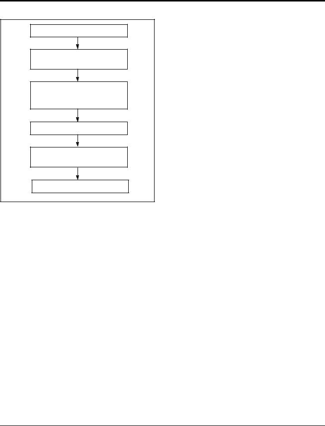
Figure 1. X76F640 Device Operation
LOAD COMMAND BYTE
LOAD 8-BYTE
PASSWORD
VERIFY PASSWORD
ACCEPTANCE BY
USE OF PASSWORD ACK POLLING
LOAD 2 BYTE ADDRESS
READ/WRITE
DATA BYTES
Twc OR DATA ACK POLLING
7025 FM 03
Retry Counter
The X76F640 contains a retry counter. The retry counter allows 8 accesses with an invalid password before any action is taken. The counter will increment with any combination of incorrect passwords. If the retry counter overflows, all memory areas are cleared and the device is locked by preventing any read or write array password matches. The passwords are unaffected. If a correct password is received prior to retry counter overflow, the retry counter is reset and access is granted. In order to reset the operation of a locked up device, a special reset command must be used with a RESET password.
Device Protocol
The X76F640 supports a bidirectional bus oriented protocol. The protocol defines any device that sends data onto the bus as a transmitter and the receiving device as a receiver. The device controlling the transfer is a master and the device being controlled is the slave. The master will always initiate data transfers and provide the clock for both transmit and receive operations. Therefore, the X76F640 will be considered a slave in all applications.
Clock and Data Conventions
Data states on the SDA line can change only during SCL LOW. SDA changes during SCL HIGH are reserved for indicating start and stop conditions. Refer to Figure 2 and Figure 3.
Start Condition
All commands are preceeded by the start condition, which is a HIGH to LOW transition of SDA when SCL is HIGH. The X76F640 continuously monitors the SDA and SCL lines for the start condition and will not respond to any command until this condition is met.
A start may be issued to terminate the input of a control byte or the input data to be written. This will reset the device and leave it ready to begin a new read or write command. Because of the push/pull output, a start cannot be generated while the part is outputting data. Starts are inhibited while a write is in progress.
Stop Condition
All communications must be terminated by a stop condition. The stop condition is a LOW to HIGH transition of SDA when SCL is HIGH. The stop condition is also used to reset the device during a command or data input sequence and will leave the device in the standby power mode. As with starts, stops are inhibited when outputting data and while a write is in progress.
Acknowledge
Acknowledge is a software convention used to indicate successful data transfer. The transmitting device, either master or slave, will release the bus after transmitting eight bits. During the ninth clock cycle the receiver will pull the SDA line LOW to acknowledge that it received the eight bits of data.
The X76F640 will respond with an acknowledge after recognition of a start condition and its slave address. If both the device and a write condition have been selected, the X76F640 will respond with an acknowledge after the receipt of each subsequent eight-bit word.
Reset Device Command
The reset device command is used to clear the retry counter and reactivate the device. When the reset device command is used prior to the retry counter overflow, the retry counter is reset and no arrays or passwords are affected. If the retry counter has overflowed, all memory areas are cleared and all commands are blocked and the retry counter is disabled. Issuing a valid reset device command (with reset password) to the device resets and re-enables the retry counter and re-enables the other commands. Again, the passwords are not affected.
Reset Password Command
A reset password command will clear both arrays and set all passwords to all zero.
3

X76F640
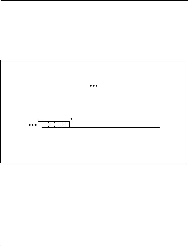
Figure 2. Data Validity
SCL
SDA
Data Stable |
Data |
|
Change |
7025 FM 04
Figure 3. Definition of Start and Stop Conditions
|
SCL |
|
|
|
|
|
|
|
|
|
|
|
|
|
|
|
|
|
SDA |
|
|
|
|
|
|
|
|
|
|
|
|
|
|
|
|
|
Start Condition |
Stop Condition |
7025 FM 05 |
|||||
|
|
|
|
|
|
|
|
|
|
|
|
|
|
||||
Table 1. X76F640 Instruction Set |
|
|
|
|
||||
|
|
|
|
|
|
|
|
|
1st Byte |
1st Byte |
|
2nd Byte |
|
|
|
|
|
after |
|
after |
|
|
|
Password |
||
|
|
|
|
|
||||
after Start |
Password |
|
Password |
Command Description |
used |
|||
|
|
|
|
|
|
|
|
|
1000 0000 |
High Address |
|
Low address |
Read (Array 0) |
Read 0 |
|||
|
|
|
|
|
|
|
|
|
1000 1000 |
High Address |
|
Low address |
Read (Array 1) |
Read 1 |
|||
|
|
|
|
|
|
|
|
|
1001 0000 |
High Address |
|
Low address |
Sector Write (Array 0) |
Write 0 |
|||
|
|
|
|
|
|
|
|
|
1001 1000 |
High Address |
|
Low address |
Sector Write (Array 1) |
Write 1 |
|||
|
|
|
|
|
|
|
|
|
1010 0000 |
0000 0000 |
0000 0000 |
Change Read 0 Password |
Read 0 |
||||
|
|
|
|
|
|
|
|
|
1010 1000 |
0000 0000 |
0000 0000 |
Change Read 1 Password |
Read 1 |
||||
|
|
|
|
|
|
|
|
|
1011 0000 |
0000 0000 |
0000 0000 |
Change Write 0 Password |
Write 0 |
||||
|
|
|
|
|
|
|
|
|
1011 1000 |
0000 0000 |
0000 0000 |
Change Write 1 Password |
Write 1 |
||||
|
|
|
|
|
|
|
|
|
1100 0000 |
0000 0000 |
0000 0000 |
Change Reset Password |
Reset |
||||
|
|
|
|
|
|
|
|
|
1110 0000 |
not used |
|
not used |
Reset Password Command |
Reset |
|||
|
|
|
|
|
|
|
|
|
1110 1000 |
not used |
|
not used |
Reset Device Command |
Reset |
|||
|
|
|
|
|
|
|
|
|
1111 0000 |
not used |
|
not used |
ACK Polling command (Ends Password operation) |
None |
|||
|
|
|
|
|
|
|
|
|
|
All the rest |
|
|
|
Reserved |
|
||
|
|
|
|
|
|
|
|
|
7025 FM T04
Notes: Illegal command codes will be disregarded.The part will respond with a “no-CK”A to the illegal byte and then return to the standby mode. All write/read operations require a password.
4
X76F640
PROGRAM OPERATIONS
Sector Programming
The sector program mode requires issuing the 8-bit write command followed by the password, password Ack command, the address and then the data bytes transferred as illustrated in figure 4. Up to 32 bytes may be transferred. After the last byte to be transferred is acknowledged a stop condition is issued which starts the nonvolatile write cycle.
Figure 4. Sector Programming
|
START |
|
|
|
COMMAND |
|
|
|
|
|
|
Write |
|
|
|
|
|
|
|
|
Write |
|
Wait tWC |
|||||||||||||||||||||||||||||||||||
|
|
|
|
7 |
|
|
|
|
|
|
|
|
0 |
|
|
|
|
|
|
|
|
|||||||||||||||||||||||||||||||||||||
|
|
|
|
|
|
|
|
|
|
|
|
|
|
|
|
|
|
|
|
|
|
|
Password |
|
|
|
|
|
|
Password |
|
|
||||||||||||||||||||||||||
|
|
|
|
|
|
|
|
|
|
|
|
|
|
|
|
|
|
|
|
|
|
|
|
|
|
|
|
|
|
|
|
|
|
|
|
|
|
|
|
|
|
|
|
|
|
|
|
|
|
|
|
|
|
|
|
|
|
OR |
SDA |
S |
|
|
|
|
|
|
|
|
|
|
|
|
|
|
|
|
|
|
|
|
|
|
|
|
|
|
|
|
|
|
|
|
|
|
|
|
|
|
|
|
|
|
|
|
|
|
|
|
|
|
|
|
|
|
|
|
Repeated |
|
|
|
|
|
|
|
|
|
|
|
|
|
|
|
|
|
|
|
|
|
|
|
|
|
|
|
|
|
|
|
|
|
|
|
|
|
|
|
|
|
|
|
|
|
|
|
|
|
|
|
|
|
|
|
|
|
|
ACK Polling |
|
|
|
|
|
|
|
|
|
|
|
|
|
|
|
|
|
|
|
|
|
|
|
|
|
|
|
|
|
|
|
|
|
|
|
|
|
ACK |
|
ACK |
ACK |
||||||||||||||||||
|
|
|
|
|
|
|
|
|
|
|
|
|
|
|
|
|
|
|
ACK |
|
Command |
|||||||||||||||||||||||||||||||||||||
|
|
|
|
|
|
|
|
|
|
|
|
|
|
|
|
|
|
|
|
|||||||||||||||||||||||||||||||||||||||
|
|
|
|
|
|
|
|
|
|
|
|
|
|
|
|
|
|
|
|
|
|
|
|
|
|
|
|
|
|
|
|
|
|
|
|
|
|
|
|
|
|
|
|
|
|
|
|
|
|
|
|
|
|
|
|
|
|
|
If ACK, Then
Password Matches
START
S 
NACK
ACK POLLING COMMAND
|
|
A15 A14 A13 A12 A11 A10 A9 A8 |
A7 A6 A5 A4 A3 A2 A1 A0 |
|
|
|
|
|
|
|
Data 0 |
|||||||||||||||||||||||||||||||||
|
|
|
|
|
|
|
|
|
|
|
|
|
|
|
|
|
|
|
|
|
|
|
|
|
|
|
|
|
|
|
|
|
|
|
|
|
|
|
|
|
|
|
|
. . . |
|
|
|
|
|
|
|
|
|
|
|
|
|
|
|
|
|
|
|
|
|
|
|
|
|
|
|
|
|
|
|
|
|
|
|
|
|
|
|
|
|
|
|
|
|
|
|
|
|
|
|
|
|
|
|
|
|
|
|
|
|
|
|
|
|
|
|
|
|
|
|
|
|
|
|
|
|
|
|
|
|
|
|
|
|
|
|
|
|
|
|
|
|
|
|
|
|
|
|
|
|
|
|
|
|
|
|
|
|
|
|
|
|
|
|
|
|
|
|
|
|
|
|
|
|
|
|
|
|
|
|
|
|
|
|
ACK |
|
|
|
|
|
|
|
|
|
|
ACK |
|
|
|
|
|
|
|
|
|
|
|
|
|
|
|
|
|
ACK |
|
|
|
|
|
|
|
|
|
|
|
ACK |
|||
|
|
|
|
|
|
|
|
|
|
|
|
|
|
|
|
|
Data 31 |
|
|
STOP |
||||||||||||||||||||||||
|
|
|
|
|
|
|
|
|
|
|
|
|
|
|
|
|
|
|
|
|
|
|
|
|
|
|
|
|
|
|
|
|||||||||||||
|
|
|
|
|
|
|
|
|
|
|
|
|
|
|
|
|
|
|
|
|
|
|
|
|
|
|
|
|
|
|
|
|
|
|
|
|
Wait tWC |
|||||||
|
|
|
|
|
|
|
|
|
|
|
|
|
|
|
|
|
|
|
|
|
|
|
|
|
|
|
|
|
|
|
|
|
S |
|||||||||||
|
|
|
|
|
|
|
|
|
|
|
|
|
|
|
|
|
|
|
|
|
|
|
|
|
|
|
|
|
|
|
|
|
||||||||||||
|
|
|
|
|
|
|
|
|
|
|
|
|
|
|
|
|
|
|
|
|
|
|
|
|
|
|
|
|
|
|
|
|
Data ACK Polling |
|||||||||||
|
|
|
|
|
|
|
|
|
|
|
|
|
|
|
|
|
|
|
|
|
|
|
|
|
|
|
|
|
|
|
|
|
||||||||||||
|
|
|
|
|
|
|
|
|
|
|
ACK |
|
|
|
|
|
|
|
|
|
|
|
|
|
|
|
|
ACK |
|
|
|
|
|
|
|
|
|
|
|
|
||||
7025 FM 07
5

X76F640
ACK Polling
Once a stop condition is issued to indicate the end of the host’s write sequence, the X76F640 initiates the internal nonvolatile write cycle. In order to take advantage of the typical 5ms write cycle, ACK polling can begin immediately. This involves issuing the start condition followed by the new command code of 8 bits (1st byte of the protocol.) If the X76F640 is still busy with the nonvolatile write operation, it will issue a “no-CK”A in response. If the nonvolatile write operation has completed, an “ACK” will be returned and the host can then proceed with the rest of the protocol.
Data ACK Polling Sequence
WRITE SEQUENCE
COMPLETED
ENTER ACK POLLING
ISSUE START
ISSUE NEW
COMMAND
CODE
ACK NO
RETURNED?
YES
PROCEED 
7025 FM 08
After the password sequence, there is always a nonvolatile write cycle. This is done to discourage random guesses of the password if the device is being tampered with. In order to continue the transaction, the X76F640
requires the master to perform an ACK polling with the specifi code of F0h. As with regular Acknowledge polling the user can either time out for 10ms, and then issue the ACK polling once, or continuously loop as described in the flow.
Password ACK Polling Sequence
PASSWORD LOAD
COMPLETED
ENTER ACK POLLING
ISSUE START |
|
ISSUE |
|
PASSWORD |
|
ACK COMMAND |
|
ACK |
NO |
RETURNED? |
|
YES |
|
PROCEED |
|
7025 FM 09
If the password that was inserted was correct, then an “ACK” will be returned once the nonvolatile cycle is over, in response to the ACK polling cycle immediately following it.
If the password that was inserted was incorrect, then a “no ACK” will be returned even if the nonvolatile cycle is over. Therefore, the user cannot be certain that the password is incorrect until the 10ms write cycle time has elapsed.
6
 Loading...