


 ™
™
SW Series Inverter/Chargers
With Revision 4.01 Software
Owner’s Manual
2001 Xantrex Technology, Inc. |
Telephone: 360/435-8826 |
SW Series Inverter/Charger |
5916 - 195th Street N. E. |
Fax: 360/435-2229 |
Part No. 2031-5 |
Arlington, WA 98223 |
www.traceengineering.com |
Rev. C: February 2001 |

2001 Xantrex Technology, Inc. |
Telephone: 360/435-8826 |
SW Series Inverter/Charger |
5916 - 195th Street N. E. |
Fax: 360/435-2229 |
Part No. 2031-5 |
Arlington, WA 98223 |
www.traceengineering.com |
Rev. C: February 2001 |
PRODUCT MATERIALS PACKAGE
Thank you for choosing Xantrex products to meet your powering needs. We make every effort to ensure that your inverter/charger is properly packaged for shipping including the following:
θOwner’s Manual;
θBattery Temperature Sensor (BTS);
θRed and black battery terminal covers with attaching hardware;
θHardware package (AC access panels with screws, crimp-on terminals);
θTrace™ bumper sticker;
If any of the above listed materials are missing from your package, or if it is unsatisfactory in any manner, please contact our Service department at 360-435-8826; or, fax this page explaining the discrepancy to 360-474-0616. Please provide:
Model Number: ________________________________
Serial Number: ________________________________
Comments:
Visit our web site at www.traceengineering.com for more information and answers to frequently asked questions.
2001 Xantrex Technology, Inc. |
Telephone: 360/435-8826 |
SW Series Inverter/Charger |
5916 - 195th Street N. E. |
Fax: 360/435-2229 |
Part No. 2031-5 |
Arlington, WA 98223 |
www.traceengineering.com |
Rev. C: February 2001 |
2001 Xantrex Technology, Inc. |
Telephone: 360/435-8826 |
SW Series Inverter/Charger |
5916 - 195th Street N. E. |
Fax: 360/435-2229 |
Part No. 2031-5 |
Arlington, WA 98223 |
www.traceengineering.com |
Rev. C: February 2001 |

|
TABLE OF CONTENTS |
TABLE OF CONTENTS |
|
IMPORTANT SAFETY INSTRUCTIONS ..................................................................................................... |
1 |
GENERAL PRECAUTIONS .................................................................................................................................... |
1 |
SPECIAL NOTICES................................................................................................................................................ |
2 |
PERSONAL PRECAUTIONS.................................................................................................................................. |
3 |
INTRODUCTION .......................................................................................................................................... |
5 |
UNIT IDENTIFICATION................................................................................................................................ |
7 |
MODEL NUMBER................................................................................................................................................... |
7 |
CONTROLS, INDICATORS AND COMPONENTS...................................................................................... |
9 |
CONTROL PANEL.................................................................................................................................................. |
9 |
AC SIDE ............................................................................................................................................................... |
12 |
DC SIDE ............................................................................................................................................................... |
14 |
INSTALLATION.......................................................................................................................................... |
15 |
QUICK INSTALL ................................................................................................................................................... |
16 |
COMPLETE INSTALL........................................................................................................................................... |
17 |
FUNCTIONAL TEST .................................................................................................................................. |
31 |
MENU SYSTEM.......................................................................................................................................... |
33 |
OVERVIEW .......................................................................................................................................................... |
33 |
USER MENU MAP................................................................................................................................................ |
34 |
SETUP MENU MAP.............................................................................................................................................. |
35 |
USER MENU ........................................................................................................................................................ |
36 |
SETUP MENU ...................................................................................................................................................... |
44 |
OPERATION............................................................................................................................................... |
57 |
THEORY OF OPERATION ................................................................................................................................... |
57 |
POWER VS. EFFICIENCY ................................................................................................................................... |
59 |
INVERTER CAPACITY VS TEMPERATURE ....................................................................................................... |
60 |
OPERATING MODES........................................................................................................................................... |
61 |
INVERTER MODE ................................................................................................................................................ |
62 |
CHARGER MODE ................................................................................................................................................ |
64 |
INVERTER/CHARGER MODE ............................................................................................................................. |
69 |
GENERATOR SUPPORT MODE ......................................................................................................................... |
71 |
AUTOMATIC GENERATOR CONTROL MODE ................................................................................................... |
73 |
UTILITY BACKUP MODE ..................................................................................................................................... |
81 |
UTILITY INTERACTIVE MODE ............................................................................................................................ |
83 |
ENERGY MANAGEMENT MODE......................................................................................................................... |
90 |
PEAK LOAD SHAVING MODE............................................................................................................................. |
92 |
IN BRIEF............................................................................................................................................................... |
92 |
LOW BATTERY TRANSFER (LBX) MODE .......................................................................................................... |
93 |
USING MULTIPLE INVERTERS........................................................................................................................... |
95 |
TECHNICAL INFORMATION ..................................................................................................................... |
99 |
BATTERY TYPE ................................................................................................................................................... |
99 |
BATTERY SIZING............................................................................................................................................... |
101 |
BATTERY BANK SIZING.................................................................................................................................... |
102 |
BATTERY CARE AND MAINTENANCE ............................................................................................................. |
104 |
BATTERY INSTALLATION ................................................................................................................................. |
106 |
BATTERY HOOK-UP CONFIGURATIONS......................................................................................................... |
107 |
BATTERY CABLE INDUCTANCE ...................................................................................................................... |
110 |
APPLICATIONS.................................................................................................................................................. |
111 |
TROUBLESHOOTING GUIDE............................................................................................................................ |
112 |
INVERTER/CHARGER TERMINOLOGY............................................................................................................ |
115 |
SPECIFICATIONS AND FEATURES (60 Hz Models) ........................................................................................ |
118 |
SPECIFICATIONS AND FEATURES (50 Hz Models) ........................................................................................ |
119 |
DIMENSIONS ..................................................................................................................................................... |
121 |
INSTALLATION DIAGRAMS .............................................................................................................................. |
121 |
USER SETTINGS WORKSHEETS..................................................................................................................... |
123 |
2001 Xantrex Technology, Inc. |
Telephone: 360/435-8826 |
SW Series Inverter/Charger |
5916 - 195th Street N. E. |
Fax: 360/435-2229 |
Part No. 2031-5 |
Arlington, WA 98223 |
www.traceengineering.com |
Rev. C: February 2001 |

TABLE OF CONTENTS
APPENDIX ................................................................................................................................................ |
128 |
OPTIONS ........................................................................................................................................................... |
128 |
OTHER PRODUCTS .......................................................................................................................................... |
129 |
REFERENCE TABLES AND GRAPHS .............................................................................................................. |
130 |
STORAGE CHECKLIST ..................................................................................................................................... |
133 |
WARRANTY/REPAIR INFORMATION .................................................................................................... |
135 |
LIMITED WARRANTY........................................................................................................................................ |
135 |
WARRANTY REGISTRATION ........................................................................................................................... |
135 |
LIFE SUPPORT POLICY.................................................................................................................................... |
135 |
WARRANTY OR REPAIR SERVICE REQUIRED.............................................................................................. |
136 |
INDEX ....................................................................................................................................................... |
137 |
2001 Xantrex Technology, Inc. |
Telephone: 360/435-8826 |
SW Series Inverter/Charger |
5916 - 195th Street N. E. |
Fax: 360/435-2229 |
Part No. 2031-5 |
Arlington, WA 98223 |
www.traceengineering.com |
Rev. C: February 2001 |

|
TABLE OF CONTENTS |
INDEX OF FIGURES |
|
Figure 1, Identification Label .................................................................................................................. |
7 |
Figure 2, SW Series Inverter/Charger .................................................................................................... |
9 |
Figure 3, Control Panel........................................................................................................................... |
9 |
Figure 4, AC Side |
12 |
Figure 5, Internal Components and Indicators ..................................................................................... |
13 |
Figure 6, Aux and .................................................................................................Gen Control Relays |
14 |
Figure 7, DC Side ................................................................................................................................. |
14 |
Figure 8, Air Flow ........................................................................................................Intake Location |
18 |
Figure 9, AC Input/Output ......................................................................................Power Connection |
19 |
Figure 10, Warning .....................................................................................................................Label |
21 |
Figure 11, Battery ..................................................................................to Inverter Cable Connection |
24 |
Figure 12, Neutral ...........................-To-Ground Bond Switching: No External AC Source Connected |
27 |
Figure 13, Neutral ................................-To-Ground Bond Switching: External AC Source Connected |
28 |
Figure 14, Neutral .......................................-To-Ground Bond Switching: Neutral Bonded To Ground |
28 |
Figure 15, Multiple .............................................................................................Point Ground System |
29 |
Figure 16, Single Point ...............................................................................................Ground System |
29 |
Figure 17, Trace™ ........................................................... |
57 |
Figure 18, Trace™ ................................................................... |
58 |
Figure 19, Trace™ .................................................................................. |
59 |
Figure 20, Inverter ......................................................................................Capacity vs. Temperature |
60 |
Figure 21, Three-Stage ............................................................................................Battery Charging |
64 |
Figure 22, BTS (Battery ....................................................................................Temperature Sensor) |
65 |
Figure 23, Two Wire ..........................................................................................Start Wiring Diagram |
76 |
Figure 24, Three Wire ..............................................................Start Wiring Diagram (HONDA Type) |
77 |
Figure 25, Three Wire .................................................................Start Wiring Diagram (ONAN Type) |
77 |
Figure 26, Relay RY7 ...........................................................................................and RY8 Sequence |
78 |
Figure 27, Selling ......Power From A DC Charging Source; Hypothetical Time Of Day Oper. History |
85 |
Figure 28, Selling ......Power Stored In The Batteries; Hypothetical Time Of Day Operational History |
86 |
Figure 29, Utility Interactive ..............................Line-Tie System With Battery Backup Flow Diagram |
88 |
Figure 30, Overvoltage ......................................................................................Protection for Battery |
89 |
Figure 31, Series Configuration: .......................................................................6-Volt Battery Wiring |
107 |
Figure 32, Series Configuration: .....................................................................12-Volt Battery Wiring |
107 |
Figure 33, Parallel ...................................................................Configuration: 12-Volt Battery Wiring |
108 |
Figure 34, Series- ..........................................................Parallel Configuration: 6-Volt Battery Wiring |
109 |
Figure 35, Series- ........................................................Parallel Configuration: 12-Volt Battery Wiring |
109 |
Figure 36, AC Waveforms.................................................................................................................. |
116 |
Figure 37, SW Series .................Dimensions: With AC Access Covers – Showing Knockout Sizes |
120 |
Figure 38, Installation ................Diagram, 120 VAC, 1 Phase, Grid Connected, Generator Backup |
121 |
Figure 39, Installation ...................Diagram, 240 VAC, 3 Wire, Grid Connected, Generator Backup |
122 |
Figure 40, AWG Wire .................................................................................................................Size |
131 |
2001 Xantrex Technology, Inc. |
Telephone: 360/435-8826 |
SW Series Inverter/Charger |
5916 - 195th Street N. E. |
Fax: 360/435-2229 |
Part No. 2031-5 |
Arlington, WA 98223 |
www.traceengineering.com |
Rev. C: February 2001 |

TABLE OF CONTENTS
INDEX OF TABLES |
|
Table 1, AC Input and Output Wiring Connections .............................................................................. |
19 |
Table 2, Minimum Recommended Battery Cable Size vs. Cable Length............................................. |
22 |
Table 3, Battery Cable To Maximum Breaker/Fuse Size ..................................................................... |
23 |
Table 4, Charging Setpoints For Common Battery Types.................................................................... |
67 |
Table 5, Typical Wattage Of Common Appliances ............................................................................ |
101 |
Table 6, Battery Charging: Charging Setpoints .................................................................................. |
104 |
Table 7, Battery State of Charge Voltage ........................................................................................... |
105 |
Table 8, Battery Cable Inductance ..................................................................................................... |
110 |
Table 9, Power Consumption Of Common Appliances ...................................................................... |
130 |
Table 10, AWG to Metric Wire Conversion Chart .............................................................................. |
130 |
Table 11, Minimum Recommended Battery Cable Size vs. Cable Length......................................... |
131 |
Table 12, Battery Cable to Maximum Breaker/Fuse Size................................................................... |
131 |
Table 13, Recommended Minimum AC Wire Sizes (75° C)............................................................... |
132 |
Table 14, Knockout/Hole Size To Conduit Size Required .................................................................. |
132 |
Table 15, Safety Ground Wire Sizes .................................................................................................. |
132 |
2001 Xantrex Technology, Inc. |
Telephone: 360/435-8826 |
SW Series Inverter/Charger |
5916 - 195th Street N. E. |
Fax: 360/435-2229 |
Part No. 2031-5 |
Arlington, WA 98223 |
www.traceengineering.com |
Rev. C: February 2001 |

IMPORTANT SAFETY INSTRUCTIONS
IMPORTANT SAFETY INSTRUCTIONS
SAVE THESE INSTRUCTIONS!
This manual contains important safety and operating instructions as prescribed by UL Standards for the Trace™ SW Series Inverter/Chargers for use in residential and commercial applications. This manual specifically covers products with the revision 4.01 software.
The 120 VAC/60 Hertz models of the SW Series Inverter/Chargers are ETL listed to UL Standard 1741 (Draft), Static Inverters and Charge Controllers for use in Photovoltaic Systems. The 12 and 24 VDC, 120 VAC/60 Hertz models of the SW Series Inverter/Chargers are ETL listed to UL standard 458, Power
Converters/Inverters and Power Converter/Inverter Systems for Land Vehicles and Marine Craft.
The 120 VAC/60 Hertz models of the SW Series Inverter/Chargers are also ETL listed to Canadian Standard CSA - C 22.2 No. 107.1 - M1, Commercial and Industrial Power Supplies.
The following Model Numbers of the SW Series Inverter/Chargers listed above comply with the following EU directives:
•89/336/EEC, “Council Directive of 3 May 1989 on the approximation of the laws of Member States relating to Electromagnetic compatibility” (EMC)
•73/23/EEC, “Council Directive of 19 February 1973 on the harmonization of the laws of Member States relating to electrical equipment for use within certain voltage limits” (LVD)
SW2612E |
SW4548AHC |
SW4548EPV |
SW2612A |
SW3048E |
SW2612EHC SW4548EHC |
SW2612AHC |
SW3048AHC |
SW4548E3PH |
|
SW3024E |
SW3048EHC |
SW3024E |
SW3048EPV |
SW3048E3PH |
SW3048E |
SW3024AHC |
SW3024A |
SW3048APV |
SW4548APV |
SW3048A |
SW3024EHC |
SW3048E |
SW4548E |
SW4548A |
The compliance of the above mentioned products with the Directives is confirmed through the application of the following essential requirements:
Emissions and Immunity |
|
Safety |
EN 50091-1 |
|
EN 50091-2 and |
|
EN 60950 |
|
|
|
NOTE: To achieve compliance to EN50091-1, Conducted RF emissions, product must not be connected to AC mains. Compliance is assured for off-grid applications only.
As the manufacturer we declare under our sole responsibility that the above mentioned products comply with the above named directives.
GENERAL PRECAUTIONS
1.Before using the SW Series Inverter/Charger, read all instructions and cautionary markings on:
(a)the inverter/charger; (b) the batteries and; (c) all appropriate sections of this manual.
WARNING - To reduce risk of injury, charge only deep-cycle lead acid, lead antimony, lead calcium, gel cell, absorbed glass mat, or NiCad/NiFe type rechargeable batteries. Other types of batteries may burst, causing personal injury and damage.
2.Do not expose inverter/charger to rain, snow or liquids of any type. The inverter is designed for indoor mounting only. Protect the inverter from splashing if used in vehicle applications.
2001 Xantrex Technology, Inc. |
Telephone: 360/435-8826 |
SW Series Inverter/Charger |
5916 - 195th Street N. E. |
Fax: 360/435-2229 |
Part No. 2031-5 |
Arlington, WA 98223 |
www.traceengineering.com |
Rev. C: February 2001 |
Page
1
IMPORTANT SAFETY INSTRUCTIONS
3.Use of battery cable or custom attachment not recommended or sold by Xantrex Technology Inc. for the SW Series Inverter/Charger may result in a risk of fire, electric shock, or injury to persons.
4.Do not disassemble the inverter/charger. Take it to a qualified service center when service or repair is required. Incorrect re-assembly may result in a risk of electric shock or fire.
5.To reduce risk of electric shock, disconnect all wiring before attempting any maintenance or cleaning. Turning off the inverter will not reduce this risk. Solar modules produce power when exposed to light. Cover them with opaque material before servicing any connected equipment.
WARNING – RISK OF EXPLOSIVE GASSES
(a)WORKING IN VICINITY OF A LEAD ACID BATTERY IS DANGEROUS. BATTERIES GENERATE EXPLOSIVE GASES DURING NORMAL BATTERY OPERATION. FOR THIS REASON, IT IS OF UTMOST IMPORTANCE THAT EACH TIME BEFORE SERVICING EQUIPMENT IN THE VICINITY OF THE BATTERY, YOU READ THIS MANUAL AND FOLLOW THE INSTRUCTIONS EXACTLY.
(b)To reduce risk of battery explosion, follow the instructions in this manual and those published by the battery manufacturer as well as manufacturer of any additional equipment used in the vicinity of the battery. Review all cautionary markings on these products.
SPECIAL NOTICES
1.Tools required to make AC and DC wiring connections: Wire strippers; 1/2" (13MM) open-end or socket wrench; Phillips #2 screwdriver; flat blade 1/4" (6MM) screwdriver.
2.No terminals or lugs are required for hook-up of the AC wiring. AC wiring must be copper wire and rated for 75° C or higher. The maximum wire size for the AC terminals is #6 AWG (4.11 mm diameter). Battery cables must be rated for 75° C or higher. Crimped and sealed copper ring terminal lugs with a 5/16 hole should be used to connect the battery cables to the DC terminals of the inverter/charger. Soldered cable lugs are also acceptable.
3.Torque all AC wiring connections to 20 inch-pounds. Torque all DC cable connections to 10-15 footpounds. Avoid dropping metal tools onto the batteries. A short-circuit could result in a spark, fire or possible explosion.
4.This inverter/charger is designed for use with a battery supply with a nominal voltage that matches the last two digits of the model number (e.g., 12 Volt with an SW2512).
5.For instructions on mounting, see the MOUNTING section on page 17 of this manual.
NOTE: Do not use the keyhole mounting slots for permanent installations. For battery installation and maintenance refer to the battery manufacturer’s instructions.
6.No AC or DC disconnects are provided as an integral part of this inverter. Both AC and DC disconnects must be provided as part of the system installation. Refer to the INSTALLATION section beginning on page 15 for more information.
7.No overcurrent protection for the battery supply is provided as an integral part of this inverter. Overcurrent protection of the battery cables must be provided as part of the system installation. Refer to the INSTALLATION section beginning on page 15 and the DC DISCONNECT AND OVERCURRENT PROTECTION section on page 23 for more information.
8.No over current protection for the AC output wiring is provided as an integral part of this inverter. Overcurrent protection of the AC output wiring must be provided as part of the system installation. Refer to the INSTALLATION section on page 15 and the AC WIRING section on page 18 for more information.
9.The AC output neutral conductor and DC negative conductors are not connected (bonded) to the inverter chassis. Both the input and output conductors are isolated from the enclosure and each other. System grounding, if required by sections 690-40, and 690-42 of the National Electric Code, ANSI/NFPA 70-1996, is the responsibility of the system installer. All installations must comply with local and national electrical codes and standards.
Page
2
2001 Xantrex Technology, Inc. |
Telephone: 360/435-8826 |
SW Series Inverter/Charger |
5916 - 195th Street N. E. |
Fax: 360/435-2229 |
Part No. 2031-5 |
Arlington, WA 98223 |
www.traceengineering.com |
Rev. C: February 2001 |
IMPORTANT SAFETY INSTRUCTIONS
10.GROUNDING INSTRUCTIONS - This inverter/battery charger should be connected to a grounded, permanent wiring system. For most installations, the negative battery conductor should be bonded to the grounding system at one (and only one point) in the system. All installations should comply with national and local codes and ordinances. Refer to the SYSTEM GROUNDING section on page 26 for more information.
PERSONAL PRECAUTIONS
1.Someone should be within range of your voice or close enough to come to your aid when you work near batteries.
2.Have plenty of fresh water and soap nearby in case battery acid contacts skin, clothing, or eyes.
3.Wear complete eye protection and clothing protection. Avoid touching eyes while working near batteries. Wash your hands when done.
4.If battery acid contacts skin or clothing, wash immediately with soap and water. If acid enters eye, immediately flood eye with running cool water for at least 15 minutes and get medical attention immediately.
(a)Baking soda neutralizes lead acid battery electrolyte.
(b)Vinegar neutralizes spilled NiCad and NiFe battery electrolyte.
(c)Keep a supply on hand in the area of the batteries.
5.NEVER smoke or allow a spark or flame in vicinity of a battery or generator.
6.Be extra cautious to reduce the risk of dropping a metal tool onto batteries. It could short-circuit the batteries or other electrical parts that may result in a spark which could cause an explosion.
7.Remove personal metal items such as rings, bracelets, necklaces, and watches when working with a battery. A battery can produce a short-circuit current high enough to weld a ring or the like to metal, causing severe burns.
8.NEVER charge a frozen battery.
9.If necessary to remove the battery, make sure all accessories are off. Then, remove the grounded terminal from the battery first.
10.If a remote or automatic generator control system is used, disable the automatic starting circuit and/or disconnect the generator from its starting battery while performing maintenance to prevent accidental starting.
11.Provide ventilation to outdoors from the battery compartment. The battery enclosure should be designed to prevent accumulation and concentration of hydrogen gas in “pockets” at the top of the compartment. Vent the battery compartment from the highest point. A sloped lid can also be used to direct the flow to the vent opening location.
12.Clean battery terminals. Be careful to keep corrosion from coming in contact with eyes.
13.Study all the battery manufacturer’s specific precautions, such as removing or not removing cell caps while charging and recommended rates of charge.
14.For flooded lead acid batteries, add distilled water in each cell until the battery acid reaches the level specified by the battery manufacturer. This helps purge excessive gas fumes from the cells. Do not overfill. For a battery without cell caps, carefully follow the manufacturer’s recharging instructions.
2001 Xantrex Technology, Inc. |
Telephone: 360/435-8826 |
SW Series Inverter/Charger |
5916 - 195th Street N. E. |
Fax: 360/435-2229 |
Part No. 2031-5 |
Arlington, WA 98223 |
www.traceengineering.com |
Rev. C: February 2001 |
Page
3

IMPORTANT SAFETY INSTRUCTIONS
Page
4
2001 Xantrex Technology, Inc. |
Telephone: 360/435-8826 |
SW Series Inverter/Charger |
5916 - 195th Street N. E. |
Fax: 360/435-2229 |
Part No. 2031-5 |
Arlington, WA 98223 |
www.traceengineering.com |
Rev. C: February 2001 |

INTRODUCTION
INTRODUCTION
Congratulations! You are the proud owner of the finest inverter on the market today - and one very complex piece of equipment. The Trace™ Sine wave (SW Series) Inverter/Charger has many features and capabilities previously either non-existent, or found only in separate products.
With proper installation, the inverter will operate satisfactorily for many applications straight out of the box, using the factory default settings. To fully utilize the inverter's generator interactive, or utility interactive capabilities, it is necessary to understand the way the inverter operates and then tailor its operation via the Control Panel and the USER and SETUP menu systems. This manual will provide the necessary information. However, it is recommended that you consult with your authorized dealer to ensure correct installation and maximum utilization of the numerous features of this product. If you do not understand any aspect of installation, contact your authorized Xantrex dealer/installer for assistance.
If you intend to operate the inverter in a utility interactive mode, in which power will be sold to the utility, you must contact the local utility office and get their approval. The utility may require additional information that may not be included in this manual. Please contact your authorized Xantrex dealer/installer for assistance.
As a minimum, you should read the sections of the manual that relate to your type of installation. The MENU SYSTEM section, beginning on page 33, explains how to make changes to the inverter’s user/setup menus. The OPERATION section, beginning on page 57, explains how the inverter works in each of its different operating modes. Focus on the operating modes that relate best to your type of installation and make the appropriate selections and adjustments. Installation diagrams are provided for many of the various applications. This menu system provides control of the inverter, allows features to be enabled, and allows setting of operating parameters.
This is a long manual and much of it is fairly technical. Throughout this manual terms may be used that are unfamiliar, see the INVERTER/CHARGER TERMINOLOGY glossary on page 115 for clarification. If you are an insomniac, properly used, this manual is guaranteed to provide several good nights of sleep.
Note: This manual is specific to the REVISION 4.01 software. Some features discussed may not be included in previous software revisions provided in inverters manufactured before March 1996.
You can verify that the inverter is using REVISION 4.01 software by checking under the TRACE ENGINEERING (3) menu heading. The second menu item should read REVISION 4.01. If your inverter includes a previous software version, please contact your authorized Xantrex dealer regarding upgrade options.
2001 Xantrex Technology, Inc. |
Telephone: 360/435-8826 |
SW Series Inverter/Charger |
5916 - 195th Street N. E. |
Fax: 360/435-2229 |
Part No. 2031-5 |
Arlington, WA 98223 |
www.traceengineering.com |
Rev. C: February 2001 |
Page
5

INTRODUCTION
Page
6
2001 Xantrex Technology, Inc. |
Telephone: 360/435-8826 |
SW Series Inverter/Charger |
5916 - 195th Street N. E. |
Fax: 360/435-2229 |
Part No. 2031-5 |
Arlington, WA 98223 |
www.traceengineering.com |
Rev. C: February 2001 |
UNIT IDENTIFICATION
UNIT IDENTIFICATION
This section describes the marking and location of the model and serial numbers for SW Series Inverter/Chargers. Use this section to determine the type and model of your inverter/charger. The unit identification label on the left side panel of the inverter/charger will show the serial number, model number, listings, ratings, and date of manufacture.
Model Number
DC Input Voltage
Operating Range
AC Input/Output |
Quarter and Year of |
Phase, |
Manufacture |
Waveform, |
|
Frequency and |
Product Code and Serial |
Voltage |
Number |
Figure 1, Identification Label
MODEL NUMBER
The Model Number of your inverter determines the different features your unit may have. Consider the following unit with a SW4024 model number:
SW |
40 |
24 |
* |
Model |
Power |
Nominal DC |
AC Voltage/Options |
|
|
Voltage |
|
Model: The first letter(s) (SW) indicate the model, in this case the SW Series.
Power: The first and second positions in the model number indicate the continuous AC power output in hundreds of VA (Volt-Amps). Power levels available start at 2500 up to 5500 Volt-Amps with different DC voltages. In the example above, 40 would stand for a 4000 VA (4 kVA), continuous-output inverter.
Input/Output DC Voltage: The number (24) following the power rating indicates an inverter/charger that is designed to convert 24 VDC input to an AC voltage output, and charge 24 VDC batteries when powered by the same AC voltage. Available DC voltages are 12, 24 and 48 volt models.
Input/Output AC Voltage/Options: The letter following the power rating indicates what AC voltage and frequency or particular option this inverter/charger is specifically designed to provide. No letter after the DC voltage number indicates an AC voltage of 120 VAC/60 Hz and requires the same AC voltage and frequency (120 VAC/60 Hz) to charge the inverter batteries. Available voltages range from 105 to 240 VAC at 50 or 60 Hz.
See the SPECIFICATIONS AND FEATURES section, on page 118, for the different models available.
2001 Xantrex Technology, Inc. |
Telephone: 360/435-8826 |
SW Series Inverter/Charger |
5916 - 195th Street N. E. |
Fax: 360/435-2229 |
Part No. 2031-5 |
Arlington, WA 98223 |
www.traceengineering.com |
Rev. C: February 2001 |
Page
7

UNIT IDENTIFICATION
Page
8
2001 Xantrex Technology, Inc. |
Telephone: 360/435-8826 |
SW Series Inverter/Charger |
5916 - 195th Street N. E. |
Fax: 360/435-2229 |
Part No. 2031-5 |
Arlington, WA 98223 |
www.traceengineering.com |
Rev. C: February 2001 |
CONTROLS, INDICATORS AND COMPONENTS
CONTROLS, INDICATORS AND COMPONENTS
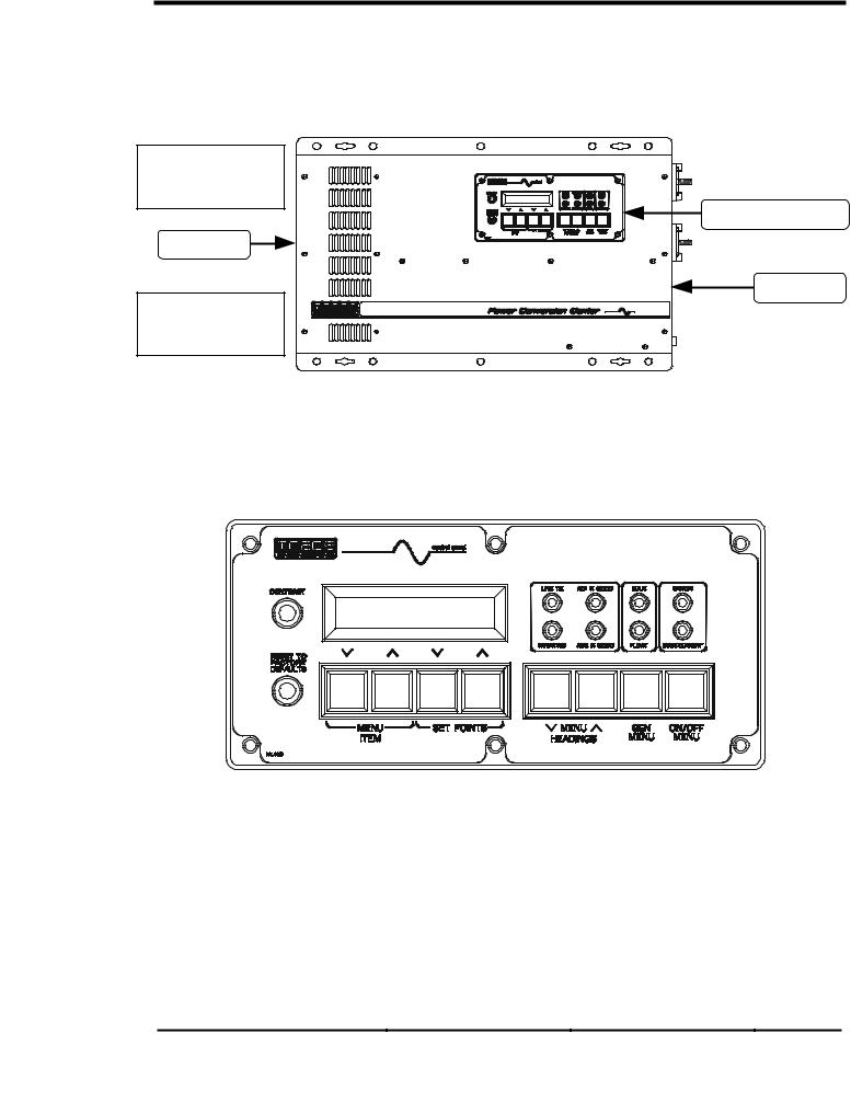
The SW Series Inverter/Chargers have an integral, full function Control Panel with LED status indicators. The following components are also included: inverter/charger circuit breaker; battery temperature sensor (BTS) port, remote port, and a stacking port.
Stacking Interface
Remote Interface
Control Panel
AC Side
DC Side
BTS Sensor Input
Circuit Breaker
Figure 2, SW Series Inverter/Charger
CONTROL PANEL
The Control Panel, on the front of the SW Series Inverter/Charger, provides the controls and displays needed to adjust, control and monitor the operation of the unit. The control panel is operational whenever DC power is applied to the inverter DC input terminals.
Figure 3, Control Panel
Eight pushbuttons are used to select the various menus, menu items and operating setpoint values for the unit, including the ability to turn the inverter on and off. A Liquid Crystal Display (LCD) presents the various system settings and data as selected by the operation of the MENU BUTTONS on the control panel. Eight LED indicators are provided to show the operating condition of the inverter, battery charger, AC inputs and self-protection systems.
DISPLAY
The Liquid Crystal Display (LCD) displays data as selected by the menu buttons. Refer to the USER MENU, beginning on page 36, and the SETUP MENU, beginning on page 44, for specific information on the Menu Items, functions and display information.
2001 Xantrex Technology, Inc. |
Telephone: 360/435-8826 |
SW Series Inverter/Charger |
5916 - 195th Street N. E. |
Fax: 360/435-2229 |
Part No. 2031-5 |
Arlington, WA 98223 |
www.traceengineering.com |
Rev. C: February 2001 |
Page
9

CONTROLS, INDICATORS AND COMPONENTS
CONTRAST CONTROL
The CONTRAST adjustment enables you to adjust the contrast of the LCD display screen to accommodate changing lighting conditions. Less contrast is usually preferable in brighter lighting conditions.
RESET TO FACTORY DEFAULTS BUTTON
The RESET TO FACTORY DEFAULTS button returns all of the inverter settings (except for the TIME OF DAY settings) to the factory default values. The default values will be re-entered only when this button is pushed from a specific menu item in the USER MENU. You must first select the TRACE ENGINEERING
(3) menu heading and then go to the first menu item, which will display “PRESS RESET NOW FOR DEFAULTS”. Once this reset button is pressed from this menu item, you must reprogram all settings required by your installation into the inverter.
Removing DC power from the inverter will also return the inverter to the factory default values (including the TIME OF DAY settings). You must then reprogram the inverter with the required settings for proper operation of your system. Recording your settings on the USER SETTINGS WORKSHEET, in the TECHNICAL INFORMATION section of this manual, will make the reprogramming of the inverter much easier.
The reset button is also used to re-synchronize the remote control (SWRC) display if the characters become jumbled. Pressing the reset button anywhere in the menu system (except the PRESS RESET NOW FOR DEFAULTS menu item) will re-synchronize the display, but the default values will not be reset.
MENU BUTTONS
ON/OFF MENU BUTTON (Red)
Pressing the red ON/OFF MENU button at any time will take you directly to the SET INVERTER menu item of the INVERTER MODE (1) menu heading. There are four options available from this menu item. The first letter of the selected item will be underlined. Pressing the red ON/OFF MENU button will move the cursor one position to the right, selecting the next item. You can also use the SET POINTS buttons to move either right or left.
GEN MENU BUTTON (Green)
Pressing the green GEN MENU button at any time will display the SET GENERATOR menu item of the GENERATOR MODE (2) menu heading. There are four options available from this menu. The first letter of the selected item will be underlined. Pressing the green GEN MENU button will move the cursor one position to the right, selecting the next item. You can also use the SET POINTS buttons to move either right or left.
MENU ACCESS/ADJUSTMENT BUTTONS (Black)
The MENU HEADING buttons are used to move either up or down through the selection of menu headings. Once a menu heading is selected, the MENU ITEM buttons are used to move up or down through the list of related menu items. The SET POINTS buttons change the value of a parameter or select a mode, for the selected menu item.
LED STATUS INDICATORS
The Control Panel features eight colored LED indicators that identify the various operating conditions of the inverter. Unless otherwise indicated, the LED’s will be "solid" in appearance, when illuminated.
LINE TIE (Yellow)
Selecting SELL from the GRID USAGE menu item under the INVERTER SETUP (9) menu heading will enable sell mode. This should only be done with utility connected systems and after you have received the approval of the local utility. This mode allows excess power to be sent into the utility grid.
INVERTING (Yellow)
The inverter is operational and AC output is available. If this LED is blinking, the inverter is in the search mode and is looking for an AC load greater than the SET SEARCH WATTS setting.
Page
10
2001 Xantrex Technology, Inc. |
Telephone: 360/435-8826 |
SW Series Inverter/Charger |
5916 - 195th Street N. E. |
Fax: 360/435-2229 |
Part No. 2031-5 |
Arlington, WA 98223 |
www.traceengineering.com |
Rev. C: February 2001 |

CONTROLS, INDICATORS AND COMPONENTS
AC1 IN GOOD (Green)
Indicates that AC power is present at the AC HOT IN 1 and NEUTRAL IN 1 input terminals. This input is intended for utility power. When an AC source is connected to the input terminals, it will start to blink slowly (once a second) to show the AC voltage has been detected. After the inverter has connected to the AC source, the LED will be solid. If the LED starts to blink during operation, utility power has been dropped.
AC2 IN GOOD (Green)
Indicates that AC power is present at the AC HOT IN 2 and NEUTRAL IN 2 input terminals. This input is intended for generator power. When an AC source is connected to the input terminals, it will start to blink slowly (once a second) to show the AC voltage has been detected. After the inverter has connected to the AC source, the LED will be solid. If the LED starts to blink during operation, generator power may have been dropped.
This LED will also blink slowly (once a second) when the automatic generator control system is enabled. When the generator has started, it will continue to blink slowly until the generator has been connected. If the generator does not successfully start, the AC 2 IN GOOD LED will stop blinking and the red ERROR LED will turn on. The ERROR CAUSES (5) menu heading will indicate a GENERATOR SYNC ERROR condition.
BULK (Yellow)
This indicator will be on to indicate the inverter is in the Bulk or Absorption charge stage. This indicator will go off and the FLOAT indicator will illuminate when the battery voltage has been held near the SET BULK VOLTS DC setting for the time period determined by the SET ABSORPTION TIME setting from the
BATTERY CHARGING (10) menu heading.
If the EQ mode is selected from the SET GENERATOR menu item under the GENERATOR MODE (2) menu heading, the BULK LED will slowly blink while the charger completes the equalization process.
FLOAT (Green)
This indicator will be on when the battery voltage has reached the Float Stage of the charging process. It will now regulate the charging process to the SET FLOAT VOLTS DC setting from the BATTERY CHARGING (10) menu heading. The SET FLOAT VOLTS DC setting provides a maintenance charge to the battery until another Bulk Charge Cycle is initiated or the AC source is disconnected. If a generator is manually controlled and powering the battery charger, the FLOAT indicator will come on to indicate that the generator should be turned off, since the battery is now fully charged.
This indicator is also used to indicate the regulation setpoint when the inverter is operating as an Utility Interactive Inverter (SELL mode). The indicator will blink slowly to indicate the battery is regulated to the
SET BATTERY SELL VOLTS DC setting from the BATTERY SELLING (17) menu heading, and the indicator will be “solid” to indicate the battery is regulated to the SET FLOAT VOLTS DC setting from the
BATTERY CHARGING (10) menu heading.
ERROR (Red)
Indicates that an operating error has occurred (refer to the ERROR CAUSES (5) menu heading for a list of possible causes). To reset the inverter, press the red ON/OFF MENU button and then select OFF and then ON with the SET POINTS buttons or by pressing the red button several times.
This indicator will blink slowly to indicate that the AC source frequency is not well-adjusted (3 to 7 hertz from nominal). You can use the LED blink to help adjust the AC source frequency. Once the frequency is within 3 hertz of your nominal frequency, the LED will turn off.
OVERCURRENT (Red)
The load requirement has exceeded the inverter’s maximum output AC amps. A sustained overcurrent condition will require a manual reset by pressing the red ON/OFF MENU button and then selecting OFF and then ON with the SET POINTS buttons or by pressing the red button several times. Momentary flashing of the red OVERCURRENT indicator means that the inverter has reached it maximum output AC amps and has automatically reset itself. This may occur during motor startups and is acceptable.
2001 Xantrex Technology, Inc. |
Telephone: 360/435-8826 |
SW Series Inverter/Charger |
5916 - 195th Street N. E. |
Fax: 360/435-2229 |
Part No. 2031-5 |
Arlington, WA 98223 |
www.traceengineering.com |
Rev. C: February 2001 |
Page
11
CONTROLS, INDICATORS AND COMPONENTS
AC SIDE
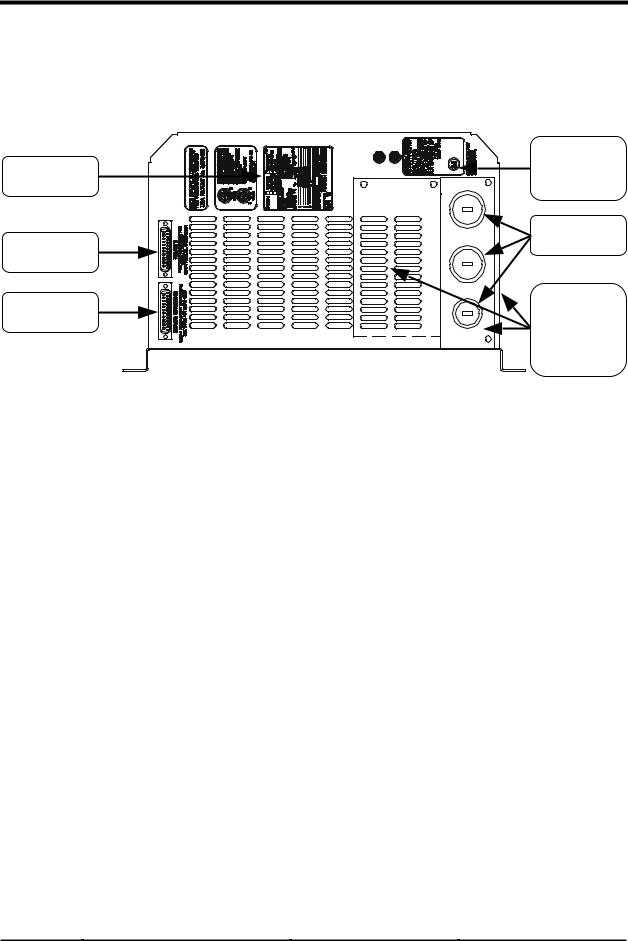
Figure 4 shows the components located on the AC side of the inverter. The removable AC Access Panels cover and protect the Internal Components and Indicators, such as the AC Terminal Block, BTS Connection, LED status indicators (for the AC1 and Gen Control relays) and the Aux and Gen Control relay terminals. Refer to the INSTALLATION section beginning on page 15, for all wiring connections.
|
Inverter/ |
|
Identification |
Charger |
|
Label |
Circuit Breaker |
|
|
Knockouts |
|
Remote |
(Also On Side} |
|
Port |
|
|
Stacking |
Three |
|
Removable |
||
Port |
||
Access Panel |
||
|
||
|
(One Panel on |
|
|
Side) |
Figure 4, AC Side
REMOTE PORT
The SW Series Inverter/Charger can be controlled remotely from the unit by plugging in a Sine wave Remote Control (SWRC) or Sine wave Communications Adapter (SWCA).
The SWRC remote control is a full function, programmable remote control with backlit LCD which duplicates the functions of the integral Control Panel.
The SWCA serial communications interface adapter allows for remote setup, adjustment, monitoring and troubleshooting of SW Series Inverter/Chargers from a personal computer and allows modem access monitoring over long distances.
See the APPENDIX, OPTIONS section, starting on page 128, for a complete description of the SWRC Remote Control and SWCA Serial Communications Adapter.
STACKING PORT
The stacking port allows multiple SW Series Inverter/Chargers to be used in the same system. The inverters can be used in a “SERIES” configuration to operate 240 Vac loads and to connect to 120/240 Vac power systems. A series stacking interface cable (SWI) is required to connect the series stacking ports of the inverters. This port is also used to connect two units in a “PARALLEL” configuration. The parallel stacking interface cable (SWI/PAR) allows two inverters to be connected to provide twice the continuous and surge capability at the same AC voltage. See the USING MULTIPLE INVERTERS section on page 95 for more information.
INVERTER/CHARGER CIRCUIT BREAKER
This circuit breaker protects the unit’s internal wiring while the unit is inverting or charging. It is not used for the pass-through current. This is not a branch-circuit rated breaker, separate output breakers are required. Press the breaker to reset (to reset on 48-volt units, move the breaker handle to the ON position).
Page
12
2001 Xantrex Technology, Inc. |
Telephone: 360/435-8826 |
SW Series Inverter/Charger |
5916 - 195th Street N. E. |
Fax: 360/435-2229 |
Part No. 2031-5 |
Arlington, WA 98223 |
www.traceengineering.com |
Rev. C: February 2001 |
CONTROLS, INDICATORS AND COMPONENTS
INTERNAL COMPONENTS AND INDICATORS
Additional components and indicators are located behind three removable AC Access Panels located on the AC Side of the unit. They include the AC Terminal Block, BTS Connector, three LED indicators and the Aux and Gen Control Relay Connectors.
RY7 (Yellow) |
RY8 (Green) |
AC1 Relay |
AC |
LED |
LED |
(Red) LED |
Terminal Block |
BTS
Connector
Aux and Gen Control |
AC |
Relay Connectors |
Safety Ground |
Figure 5, Internal Components and Indicators
LED INDICATORS
Three LED indicators allow visual indication of operation of the RY7, RY8 and AC1 relays.
RY7 (Yellow) LED
Allows visual indication of relay RY7 operation. During the automatic generator control sequence, the LED will be on to show that RY7 is closed (engaged) from the N.O. to the COM contacts, and will be off when RY7 is opened (disengaged).
RY8 (Green) LED
Allows visual indication of relay RY8 operation. During the automatic generator control sequence, the LED will be on to show that RY8 is closed (engaged) from the N.O. to the COM contacts, and will be off when RY8 is opened (disengaged).
AC1 RELAY (Red) LED
Allows visual indication of AC1 relay operation. The LED will be on when the AC1 relay is closed (engaged). This LED along with the test-jumper adjacent to the LED is used by utilities to perform voltage and frequency tests to qualify the SW Series Inverter/Charger for line-tie applications.
BTS PORT
The battery temperature sensor (BTS) can be connected (plugged in) at the RJ-11 four-conductor connector, located on the AC Circuit Board. The BTS provides information that enables the three-stage standby battery charger to “fine tune” the battery charge voltages for better charging performance, greater efficiency and longer battery life.
AC TERMINAL BLOCK
A six position terminal block is provided to make the AC connections. The terminal block is located on the AC Circuit Board. The terminal block is used to hardwire all AC input and output connections.
2001 Xantrex Technology, Inc. |
Telephone: 360/435-8826 |
SW Series Inverter/Charger |
5916 - 195th Street N. E. |
Fax: 360/435-2229 |
Part No. 2031-5 |
Arlington, WA 98223 |
www.traceengineering.com |
Rev. C: February 2001 |
Page
13
CONTROLS, INDICATORS AND COMPONENTS
AC SAFETY GROUND
The AC Safety Ground is used to connect the inverter chassis to the AC Grounding System.
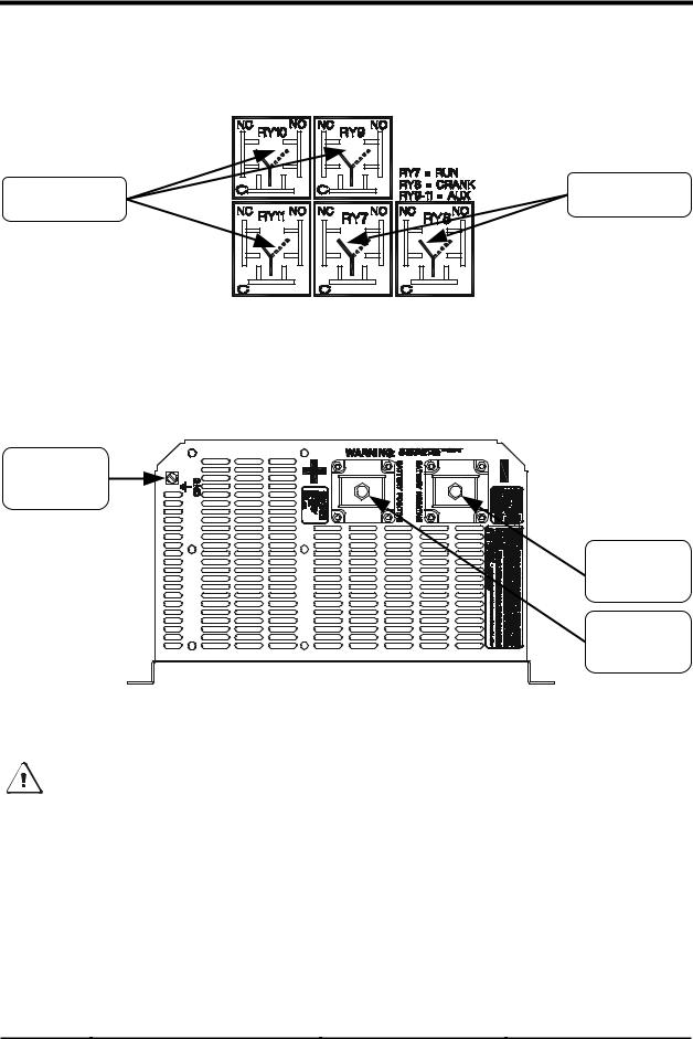
AUXILIARY AND GENERATOR CONTROL RELAY CONNECTORS
Auxiliary Control |
Generator Control |
|
Relay Connectors |
Relay Connectors |
|
Figure 6, Auxiliary and Generator Control Relay Connectors
DC SIDE
Figure 5 shows the components located on the DC side of the inverter. Refer to the INSTALLATION section for the battery wiring connections to the Battery Terminals and the DC Ground.
DC (Equipment) Ground
Battery
Terminal
(-)
Battery
Terminal
(+)
Figure 7, DC Side
BATTERY TERMINALS
Caution: Before connecting the battery cables to the inverter, verify the correct battery voltage and cable polarity using a voltmeter. The inverter is not reverse polarity protected. If the positive terminal of the battery is connected to the negative terminal of the inverter and vice versa, severe damage will result. If necessary, color-code the cables with colored tape or heat shrink tubing: RED for positive (+); BLACK for negative (-) to avoid polarity problems.
DC (EQUIPMENT) GROUND
This connection is used to connect the exposed chassis of the inverter to the DC grounding system. The terminal accepts wires from #14 AWG to #2 AWG.
Page
14
2001 Xantrex Technology, Inc. |
Telephone: 360/435-8826 |
SW Series Inverter/Charger |
5916 - 195th Street N. E. |
Fax: 360/435-2229 |
Part No. 2031-5 |
Arlington, WA 98223 |
www.traceengineering.com |
Rev. C: February 2001 |

INSTALLATION
INSTALLATION
This section is very important, since it tells you how to properly install your SW Series Inverter/Charger. It becomes very frustrating when your inverter system does not perform properly, simply because care was not taken during installation. Please read this entire section carefully. You will save time and avoid common mistakes.
This section also describes the requirements and recommendations for installing the SW Series Inverter/Charger. In the U.S., the National Electrical Code (NEC) defines the standards for both the AC and DC wiring in residential, commercial and RV applications. It will list the requirement for wire sizes, overcurrent protection and installation methods and requirements. There are still many other variables not covered by the NEC. Most are determined by the level of automatic operation, the amount of external AC and DC power to be controlled and the loads to be operated.
The NEC standards and regulations are described here in general for your convenience, and are not represented as comprehensive or complete. For comprehensive and complete official standards and regulations, write the address listed below:
NFPA - National Fire Protection Association
National Electrical Code Handbook
1 Batterymarch Park, PO Box 9101
Quincy, MA 02269-9101 617-770-3000.
Before beginning the installation of the SW Series Inverter/Charger, read all instructions. Disconnect all sources of AC and DC power to prevent accidental shock. Disable and secure all AC and DC disconnect devices and automatic generator starting devices.
All installations should meet all local codes and standards and be performed by qualified personnel such as a licensed electrician. Although the DC electrical system may be “low voltage”, significant hazards may be present, particularly from short circuits of the battery system. Inverter systems by their nature involve power from multiple sources (inverter, generator, utility, batteries, solar arrays etc.) that add hazards and complexity that can be very challenging.
After you have finished installing your unit, continue with the FUNCTIONAL TEST section on page 31. This Functional Test should be completed prior to configuring your unit’s Menu System for your specific operation.
2001 Xantrex Technology, Inc. |
Telephone: 360/435-8826 |
SW Series Inverter/Charger |
5916 - 195th Street N. E. |
Fax: 360/435-2229 |
Part No. 2031-5 |
Arlington, WA 98223 |
www.traceengineering.com |
Rev. C: February 2001 |
Page
15

INSTALLATION
QUICK INSTALL
This section provides installers, licensed electrical contractors, and knowledgeable laymen the essential steps to quickly install the Trace™ SW Series Inverter/Charger. If you haven’t had experience with the SW Series Inverter/Charger, you are urged to skip this section and read the entire INSTALLATION section before installing the inverter/charger.
MOUNTING
Mount the unit securely in a clean, dry, properly ventilated enclosure. Do not mount the unit in the same enclosure as vented or maintenance-free type vented batteries. Bolt the unit securely. Allow adequate clearance to allow access to the indicators or controls.
DC CABLING
1.Connect an appropriate sized cable from the positive batter terminal (or battery bank) to the inverter’s positive (red) terminal. See Table 12 in the Appendix to determine the proper size cable and length of run needed to use with your inverter model and for your specific application. The National Electric Code (NEC) requires the use of a DC fuse or disconnect with this cable. See Table 12 in the Appendix to determine the correct fuse or breaker to use.
2.Connect an appropriate sized cable from the negative battery terminal to the negative (black) inverter terminal. Torque all terminals to 10-15 foot-pounds. NOTE: A 'snap' caused by charging the internal capacitors may occur when first connecting the cable. This can be avoided by first removing the DC fuse or opening the disconnect in the positive battery cable.
3.Connect a cable from the inverter’s DC Chassis Ground to the system ground.
AC IN CABLING
1.See Table 13 in the Appendix to determine the appropriate AC wire size.
2.Remove the knockout from the inverter chassis and install a strain relief or conduit in which to route the AC cabling in and out.
3.Connect the black wire from the hot side of the AC power to the terminal labeled AC HOT IN 1 (AC HOT IN 2 if a generator is the AC source) on the inverter.
4.Connect the white wire from the neutral side of the AC power source to the terminal labeled NEUTRAL IN 1 (NEUTRAL IN 2 if a generator is the AC source) on the inverter.
5.Connect the green wire from the ground of the AC power source to the AC Ground Terminal of the inverter/charger.
AC OUT CABLING
1.Connect the black wire between the terminal marked AC HOT OUT to the hot bus of your AC load center or AC sub-panel.
2.Connect the white wire from the terminal marked NEUTRAL OUT to the neutral bus of your AC load center or sub-panel.
3.Connect the AC Ground Terminal of the inverter to the safety ground bus of the AC load center or sub-panel.
WRAP UP
1.Secure all wiring with wire ties or other non-conductive fasteners to prevent chafing or damage. Use strain-reliefs, grommets, or conduits to prevent damage to the wiring where it passes through any apertures. Tighten all connections to the correct torque (AC Connections at 20 inch-pounds; DC Connections at 10-15 foot-pounds).
2.Make a final check of all wiring, then reconnect to the AC power source.
3.Turn the inverter ON and check inverter operation (See the FUNCTIONAL TEST section on page 31).
Page
16
2001 Xantrex Technology, Inc. |
Telephone: 360/435-8826 |
SW Series Inverter/Charger |
5916 - 195th Street N. E. |
Fax: 360/435-2229 |
Part No. 2031-5 |
Arlington, WA 98223 |
www.traceengineering.com |
Rev. C: February 2001 |
INSTALLATION
COMPLETE INSTALL
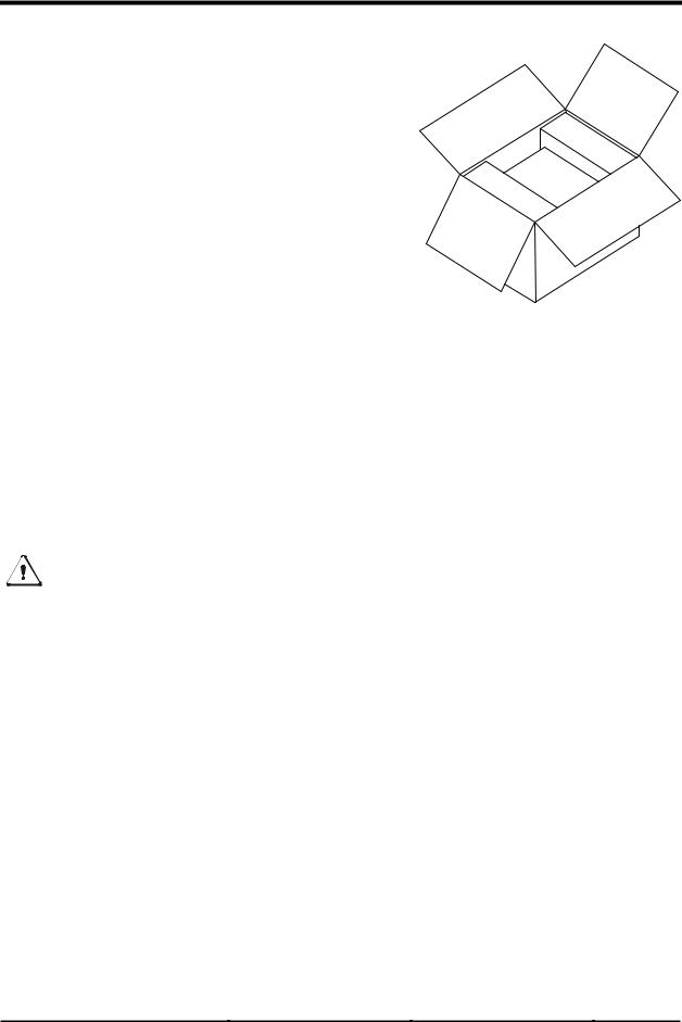
UNPACKING
Before beginning, unpack the inverter/charger; record the serial number on the inside cover of this booklet and on the warranty card. Right now, please do the following:
•Verify that you have everything listed on the Packaging Materials sheet. If any items are missing, please call Customer Service at (360) 435-8826.
•Save your “proof-of-purchase”, You will need the “proof-of- purchase” to obtain warranty service.
•Keep the original carton and packing materials. If you need to return your inverter for service, you should ship it in the original carton. It is also the best way to keep the inverter safe if it needs to be moved.
LOCATION
Inverters are sophisticated electronic devices and should be treated accordingly. Treat the inverter as you would any fine piece of electronic equipment. When selecting the location for the inverter, don't think of it in the same terms as the other interfacing equipment, e.g. batteries, diesel generators, motor generators, washing machines etc. It is a highly complex microprocessor controlled device. There are nearly 500,000 silicon junctions in its output devices and integrated circuits. The crystal oscillator runs at 4 megahertz. The drive circuitry timing is accurate to a thousandth of a second. Genetically speaking, it is a cousin to stereo equipment, television sets or computers. The use of conformal-coated circuit boards, plated copper bus bars, powder coated metal components, and stainless steel fasteners improves tolerance to hostile environments. However, in a corrosive or condensing environment (one in which humidity and/or temperature change cause water to form on components) all the ingredients for electrolysis are present - water, electricity and metals. In a corrosive or condensing environment, the life expectancy of the inverter is indeterminate and the warranty is voided.
Caution: Install the inverter in a dry, protected location away from sources of high temperature and moisture. Exposure to saltwater is particularly destructive and potentially hazardous.
Locate the inverter as close to the batteries as possible in order to keep the battery cable length short. Do not locate the inverter directly above the batteries or in the same compartment as vented batteries. Batteries generate hydrogen sulfide gas, which is very corrosive to electronic equipment and everything else. They also generate hydrogen and oxygen. If these gases accumulate, an arc caused by the connecting of battery cables or the switching of a relay could ignite the mixture. Mounting the inverter in a ventilated enclosure with sealed batteries is acceptable.
Ensure the inverter is located in an area that prevents insects and rodents from entering the inverter, as the inverter can provide a warm habitat in a cold environment. This may involve installing the inverter in an enclosure and include mesh screens or nets over any openings to ensure the unit is kept well ventilated.
This inverter can create RFI (Radio Frequency Interference). Keep this in mind when determining the placement of the inverter. You should locate the inverter as far away as possible from any electronic devices that may be susceptible to RFI.
MOUNTING
UL Standard 1741 (draft) requires that the inverter be mounted on a vertical surface (on a wall) and that the keyhole slots not be used as the only method of mounting. The purpose of the wall mounting requirement is to orient the inverter so that its bottom cover, which has no holes, will not allow burning material to be ejected in case of an internal fire.
2001 Xantrex Technology, Inc. |
Telephone: 360/435-8826 |
SW Series Inverter/Charger |
5916 - 195th Street N. E. |
Fax: 360/435-2229 |
Part No. 2031-5 |
Arlington, WA 98223 |
www.traceengineering.com |
Rev. C: February 2001 |
Page
17
INSTALLATION
Use 1/4" minimum diameter bolts for mounting. The mounting must be capable of supporting twice the weight of the inverter in order to comply with UL 1741. If this unit is used in a mobile application (i.e. RV, Boat) secure the inverter to a shelf or deck to prevent movement. Place flexible washers on the mounting screws or bolts between the shelf or deck and the inverter chassis to reduce vibration.
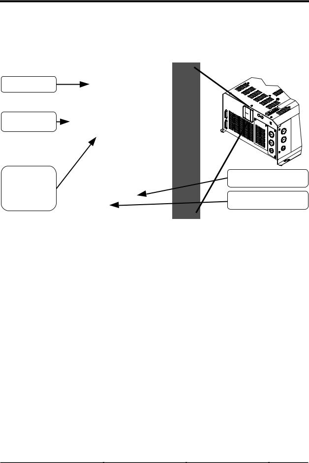
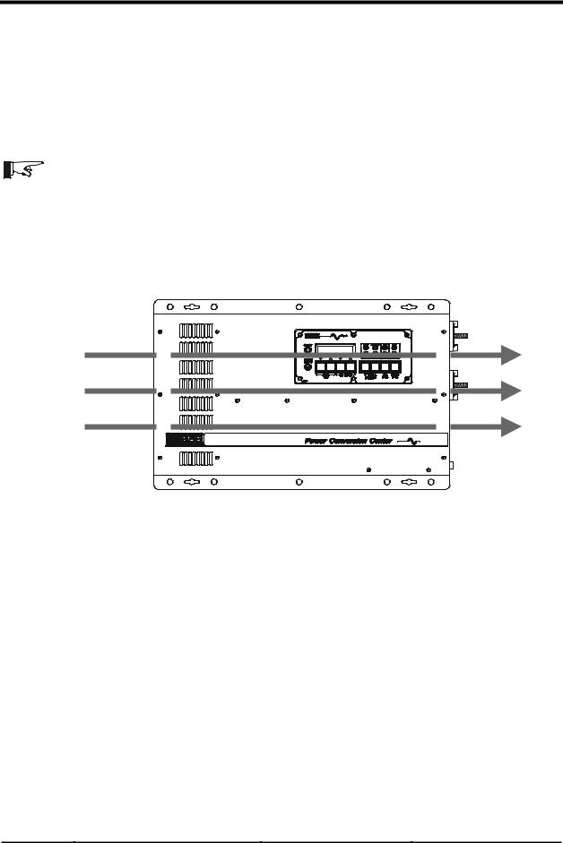
VENTILATION
Installation of the inverter in a properly ventilated enclosure is necessary for efficient operation of the unit. The inverter’s thermal shutdown point will be reached sooner than normal in a poorly ventilated environment and will result in a lower peak power output, reduced surge capability, and potentially shorter inverter life.
Note: Do not operate the inverter in a closed-in area or restrict ventilation in any way.
Testing has shown that the volume of the enclosure is not as important as the overall ventilation. A minimum airspace clearance of 1½ inches around the top and bottom and 3 inches of clearance at the left and right sides of the inverter will provide adequate ventilation. Because the top and bottom of the SW Series chassis is not vented, clearance between the enclosure and the top of the inverter is not critical. A fresh air intake port should be provided directly to the left side and an exhaust port on the right side will allow cool outside air to flow through the inverter and back out of the enclosure.
|
Top |
Left |
Right |
(AC Side) |
(DC Side) |
AIR |
|
FLOW |
|
|
Bottom |
Figure 8, Air Flow Intake Location
AC WIRING
This section describes AC wiring requirements and recommendations; including AC connections; wire sizing; overcurrent devices; GFCIs; external relays; hookup procedure; and neutral-to-ground switching. Your local electrical code and the National Electrical Code (NEC) define the standards for AC installation wiring, but there are still many installation variables to be considered. Consult the local code and the NEC for the proper wire sizes, connectors and conduit. All installations should meet all local codes and standards and be performed by qualified personnel such as a licensed electrician.
AC INPUT AND OUTPUT CONNECTIONS
A six position terminal block is provided to make the AC connections. The terminal block is located on the left-hand side of the inverter, enclosed under a cover plate (See INTERNAL COMPONENTS AND INDICATORS on page 13 for location.). The terminal block can accept up to # 6 AWG stranded wire and is used to hardwire all AC connections. For 120 VAC inverters, we recommend 6 AWG (THHN) wire for full utilization of the inverter’s 60 amp AC pass through capability. The code requires that disconnect switches be provided in the AC input and output wiring circuits. AC circuit breakers in an AC load center can be used to meet this requirement. The wiring both in and out of the inverter must also be protected from short circuits and overloads by a fuse or circuit breaker. Typically, a 60 amp circuit breaker will protect #6 AWG wiring. Consult your local code for more information and for other wire sizes.
Page
18
2001 Xantrex Technology, Inc. |
Telephone: 360/435-8826 |
SW Series Inverter/Charger |
5916 - 195th Street N. E. |
Fax: 360/435-2229 |
Part No. 2031-5 |
Arlington, WA 98223 |
www.traceengineering.com |
Rev. C: February 2001 |

INSTALLATION
Note: The three neutral terminals are common to each other and can be used in any combination or order. In a residential application, it is often easier to only connect one AC neutral wire to the inverter and make the other neutral connections at a central point such as in the AC load center, etc. In mobile installations, the AC system must have the neutral physically isolated from the ground throughout the load distribution powered by the inverter. The SW Series Inverter/Charger does not include neutral to ground switching for the AC electrical system. This must be done externally from the inverter. See the NEUTRAL- TO-GROUND BOND SWITCHING (RV AND MARINE APPLICATIONS) section on page 27 for more information.
AC Terminal Block
(TB1)
1a 1b
|
|
2b |
AC IN 1 |
|
2a |
From |
|
AC IN 2 |
|
|
Utility Power |
|
|
|
|
From |
3a |
3b |
|
Generator Power |
|
|
|
|
4a |
4b |
|
|
5a |
5b |
AC OUT |
|
|
|
To |
|
6a |
6b |
AC Loads |
Figure 9, AC Input/Output Power Connection
Before making any AC connections, make sure that the inverter is disconnected from the battery (or battery bank). Feed the wires through conduit fittings located on the left side or left bottom side of the inverter. (Note: Conduit fittings must be purchased separately and are required by code to comply with residential and commercial installations).
The AC wiring both in and out of the inverter must also be protected from short circuits and overloads by a fuse or circuit breaker. Consult the NEC or your local code for more information and for other wire sizes. Table 13 on page 132 gives suggestions for wire sizing. Follow the wiring guide on the circuit board inside the cover plate (see Figure 9, above). Connect the AC wiring as follows (from front to back when wall mounted):
Table 1, AC Input and Output Wiring Connections
AC CONNECTIONS |
AC TERMINAL BLOCK # |
WIRE COLOR |
PURPOSE |
|
|
|
|
AC HOT IN 1 |
1b |
Black (Hot) |
Utility Power |
NEUTRAL IN 1 |
3b |
White (Neutral) |
Utility Power |
AC HOT IN 2 |
2b |
Black (Hot) |
Generator |
NEUTRAL IN 2 |
4b |
White (Neutral) |
Generator |
AC HOT OUT |
6b |
Black or Red (Hot) |
AC Loads |
NEUTRAL OUT |
5b |
White (Neutral) |
AC Loads |
2001 Xantrex Technology, Inc. |
Telephone: 360/435-8826 |
SW Series Inverter/Charger |
5916 - 195th Street N. E. |
Fax: 360/435-2229 |
Part No. 2031-5 |
Arlington, WA 98223 |
www.traceengineering.com |
Rev. C: February 2001 |
Page
19

INSTALLATION
AC INSTALLATION GUIDELINES
The following steps are a basic guideline for installation and connection of the AC wiring into and out of the inverter.
1.Disconnect the inverter from the battery bank (if already connected), by either removing the DC side fuse, or opening the DC disconnect. Then remove the AC wiring compartment cover from the front of the inverter by removing the two screws on the cover.
2.If conduit will be utilized (consult code, it may be required in your installation), determine which knockout(s) will be utilized and remove them from the inverter. Using appropriate conduit connectors, fasten the conduit to the inverter. Feed all AC wiring through the conduit and into the inverter AC terminal block. Be sure to leave yourself several extra inches of wire to work with. Remember that you need at least two sets of three conductor wiring, one for AC Hot, Neutral, and Ground into the inverter, and another for AC Hot, Neutral and Ground out of the inverter to the loads. Torque all AC terminals to 10 to 15 inch-pounds.
3.Connect the Hot (black) and Neutral (white) wires from the AC source(s) to the appropriately labeled terminals in the AC terminal block. The Safety Ground (green) should be connected to the terminal stud labeled “AC Ground” bolted to the chassis. Repeat the procedure for the AC wiring going to the AC sub-panel which will power the loads, except connect these wires to the terminals labeled AC HOT OUT.
4.Inspect all wiring for proper installation and then replace the access cover using the two screws to secure it.
IMPORTANT PRECAUTION
The AC output of the inverter must at no time be connected directly to utility power or a generator. This condition can be far worse than a short circuit. If the inverter survives this condition, it will shut down until corrections are made. Connection to a utility or generator must be only done internally by the inverters built-in relays. This allows the inverter to first synchronize to the other AC sources waveform, preventing damage. Connect the utility or generator to the provided input terminals AC HOT IN 1 or AC HOT IN 2 respectively.
When the inverter output is connected directly to an external source, the inverter will shut down and indicate an error on the control panel. Checking the ERROR CAUSES menu heading will show a YES for the AC SOURCE WIRED TO OUTPUT menu item. Either determine the source of the AC or call a qualified electrician to correct the situation.
EXTERNAL TRANSFER RELAYS
It is not acceptable to switch the AC input from one AC source to another while the inverter is connected. This applies whether the inverter is in battery charging mode or inverter mode. Switching the AC input from one source to another can result in a loss of synchronization that can cause a severe overcurrent condition that is far worse than short circuiting the inverter. Two separate AC inputs are provided to eliminate the need for use of external transfer relays. If a transfer relay is used, it must provide a center “OFF” position (“break before make”) that causes a loss of input power to the inverter for a period of at least 100 milliseconds. This will allow the inverter to disconnect from the original AC input and then re-synchronize to the new AC source although the same AC input terminal is being used. During the transition period, the inverter will have to operate the load while it re-synchronizes to the new AC source (about a thirty-second period at the minimum). Most transfer relays will switch too fast for the inverter to detect - and will cause the inverter to lose synchronization with the AC source. This is indicated by the inverter shutting down upon transfer and the red overcurrent LED indicator flashing or turning on.
Manually, hand operated transfer switches may be acceptable since the transfer time can be slow enough for the inverter to detect. The switch must go through a center “off” position. They are often used to switch from one generator to another. Since the inverter has a separate AC input for a utility grid, a transfer switch is not required to switch from the utility grid to a back-up generator. The inverter will not allow the generator to be connected to the utility - if both are available, the generator will be disconnected and the inverter will connect to the utility on AC HOT IN 1.
Page
20
2001 Xantrex Technology, Inc. |
Telephone: 360/435-8826 |
SW Series Inverter/Charger |
5916 - 195th Street N. E. |
Fax: 360/435-2229 |
Part No. 2031-5 |
Arlington, WA 98223 |
www.traceengineering.com |
Rev. C: February 2001 |
INSTALLATION
120 VAC GROUND FAULT INTERRUPT OUTLETS (GFI’S)
Xantrex has tested the following 120 VAC GFI’s and found them to work satisfactorily with our inverters:
LEVITON |
6599 |
PASS & SEYMOR |
1591 4A957 |
ACE Hardware |
ACE 33238 |
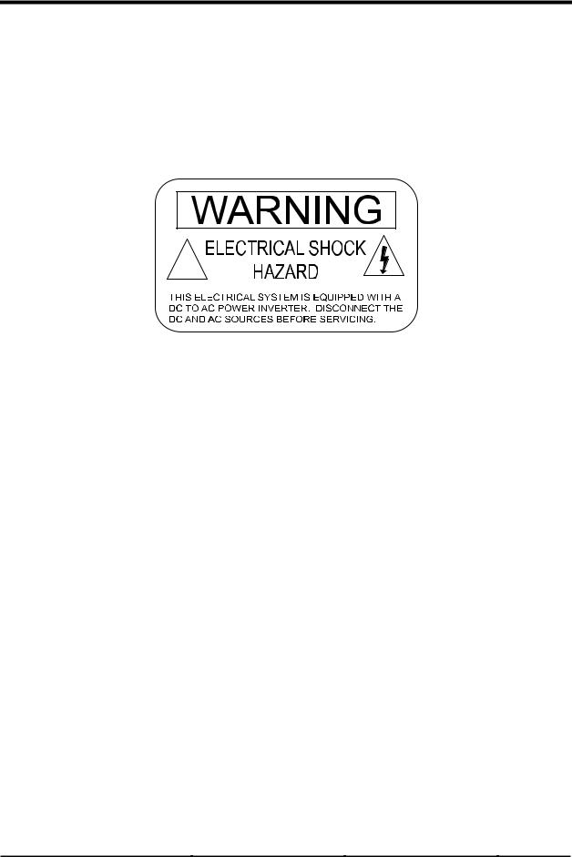
WARNING LABEL
A warning label is provided to inform all personnel that an inverter is installed in your electrical system. This label should be installed at the electrical panel that is being powered by the inverter. Be cautious until the inverter is disconnected from your electrical system.
!
Figure 10, Warning Label
2001 Xantrex Technology, Inc. |
Telephone: 360/435-8826 |
SW Series Inverter/Charger |
5916 - 195th Street N. E. |
Fax: 360/435-2229 |
Part No. 2031-5 |
Arlington, WA 98223 |
www.traceengineering.com |
Rev. C: February 2001 |
Page
21
INSTALLATION
DC WIRING
CAUTION: The inverter’s maximum peak current requirements are high. If battery cables are too small and/or connections are loose, efficiency and maximum output power are degraded. Small cables or loose connections may cause dangerous overheating and a fire.
BATTERY CABLE SIZING
The larger the battery cables the better. Undersized cables result in additional stress on the inverter, lower efficiency, reduced surge power and lower peak output voltage. Don’t use cables that are too small and degrade the efficiency that we have worked so hard to achieve and you have paid so much to own.
Also, don’t use cables that are too long - the shorter the better. The lower the DC system voltage, the shorter the cables need to be. If long cables are required, either oversize them substantially, or switch to a higher voltage system, such as 24 Vdc or 48 Vdc. On 12-Vdc system, cables may need to be doubled up (paralleled) to get maximum performance from the inverter.
NOTE: Do not separate the positive and negative cables - taping them together in parallel is best. This reduces the inductance of the wire resulting in a better waveform and reduces the current in the inverter’s filter capacitors. Make the battery cables as short as possible.
Although large cables may seem expensive, spending an additional $100 or more to ensure the performance of your inverter is a wise investment. Using cables that are too small is like putting cheap tires on a high performance sports car - the results will be disappointing.
If the system is expected to operate at the inverter’s continuous power level rating for long periods of time (over an hour), larger disconnects and cables may be required. Most systems do not operate at full capacity for periods exceeding an hour and can operate satisfactorily with the following cable and disconnects shown. If your system includes enormous batteries or has a very large DC source able to continuously power the inverter (such as a hydroelectric plant, etc.) then increasing the disconnect and cable sizes may be required to prevent nuisance tripping of a breaker or blowing of fuses.
The following table gives recommended minimum cable sizes for various cable run lengths and inverter voltages. Use only all copper cables. These recommendations may not meet all local code or NEC requirements.
|
Table 2, Minimum Recommended Battery Cable Size vs. Cable Length |
|||||
|
|
|
|
|
|
|
INVERTER |
TYPICAL |
NEC |
1 TO 3 FEET |
3 TO 5 FT |
5 TO 10 FT |
|
DC |
||||||
|
2 |
|
|
|
||
MODEL |
AMPS1 |
AMPS |
ONE WAY |
ONE WAY |
ONE WAY |
|
SW2512 |
267 Amps |
334 Amps |
#4/0 AWG/107 mm2 |
#4/0 AWG/107 mm2 |
Not Recommended |
|
SW2612E |
278 Amps |
348 Amps |
#4/0 AWG/107 mm2 |
#4/0 AWG/107 mm2 |
Not Recommended |
|
SW3024E or J |
160 Amps |
201 Amps |
#4/0 AWG/107 mm2 |
#4/0 AWG/107 mm2 |
#4/0 AWG/107 mm2 |
|
SW4024 or W, K |
214 Amps |
267 Amps |
#4/0 AWG/107 mm2 |
#4/0 AWG/107 mm2 |
#4/0 AWG/107 mm2 |
|
SW3048E or J |
80 Amps |
100 Amps |
#2/0 AWG/67.4 mm2 |
#2/0 AWG/67.4 mm2 |
#4/0 AWG/107 mm2 |
|
SW4048 or K |
107 Amps |
134 Amps |
#2/0 AWG/67.4 mm2 |
#2/0 AWG/67.4 mm2 |
#4/0 AWG/107 mm2 |
|
SW4548E or A |
120 Amps |
150 Amps |
#2/0 AWG/67.4 mm2 |
#2/0 AWG/67.4 mm2 |
#4/0 AWG/107 mm2 |
|
SW5548 |
147 Amps |
184 Amps |
#4/0 AWG/107 mm2 |
#4/0 AWG/107 mm2 |
#4/0 AWG/107 mm2 |
|
1TYPICAL DC AMPS is based on Low Battery Voltage with an efficiency of 85%.
2NEC AMPS is based on Low Battery Voltage, an efficiency of 85%, and a 125% NEC de-rating.
WARNING! Battery cables that are too small will melt and burn the first time the inverter is operated at high power levels.
Page
22
2001 Xantrex Technology, Inc. |
Telephone: 360/435-8826 |
SW Series Inverter/Charger |
5916 - 195th Street N. E. |
Fax: 360/435-2229 |
Part No. 2031-5 |
Arlington, WA 98223 |
www.traceengineering.com |
Rev. C: February 2001 |
 Loading...