


PS2.5
PS3.0
Installation and Operation Guide
Xantrex
ProsineTM 2.5 and 3.0
Inverter/Chargers

|
|
|
|
|
|
|
|
|
|
|
|
|
|
|
|
|
|
|
|
|
|
|
|
|
|
|
|
|
|
|
|
|
|
|
|
|
|
|
|
|
|
|
|
|
|
|
|
|
|
|
|
|
|
|
|
|
|
|
|
|
|
|
|
|
|
|
|
|
|
|
|
|
|
|
|
|
|
|
|
|
|
|
|
|
|
|
|
|
|
|
|
|
|
|
|
|
|
|
|
|
|
|
|
|
|
|
|
|
|
|
|
|
|
|
|
|
|
|
|
|
|
|
|
|
|
|
|
|
|
|
|
|
|
|
|
|
|
|
|
|
|
|
|
|
|
|
|
ProsineTM |
|
|
PS2.5 Inverter/Charger |
|
|
|||||||||||||||||||||||||||||||
|
|
|
|
|
|
|
|
|
|
|
|
|
|
|
|
PS3.0 Inverter/Charger |
|
|
||||||||||||||||||
Installation and Operation Guide
About Xantrex
Xantrex Technology Inc. is a world-leading supplier of advanced power electronics and controls with products from 50 watt mobile units to one MW utility-scale systems for wind, solar, batteries, fuel cells, microturbines, and backup power applications in both grid-connected and standalone systems. Xantrex products include inverters, battery chargers, programmable power supplies, and variable speed drives that convert, supply, control, clean, and distribute electrical power.
Trademarks
Xantrex is a registered trademark of Xantrex International. © 2002 Xantrex International. All rights reserved. Prosine is a registered trademark of Xantrex International.
Other trademarks, registered trademarks, and product names are the property of their respective owners and are used herein for identification purposes only.
Notice of Copyright
Installation and Operation Guide © November 2002 Xantrex International.
Disclaimer
Xantrex manufactures its products from parts and components that are new or equivalent to new, in accordance with industry-standard practices.
UNLESS SPECIFICALLY AGREED TO IN WRITING, XANTREX TECHNOLOGY INC. (“XANTREX”):
(a)MAKES NO WARRANTY AS TO THE ACCURACY, SUFFICIENCY OR SUITABILITY OF ANY TECHNICAL OR OTHER INFORMATION PROVIDED IN ITS MANUALS OR OTHER DOCUMENTATION.
(b)ASSUMES NO RESPONSIBILITY OR LIABILITY FOR LOSS OR DAMAGE, WHETHER DIRECT, INDIRECT, CONSEQUENTIAL OR INCIDENTAL, WHICH MIGHT ARISE OUT OF THE USE OF SUCH INFORMATION. THE USE OF ANY SUCH INFORMATION WILL BE ENTIRELY AT THE USER’S RISK.
Date and Revision
November 2002, Revision 3
Part number
445-0096-01-01 Rev 3
Contact information
Telephone: 1-800-670-0707 (toll free in North America) 1-604-422-2777 (outside North America)
Fax: 1-604-420-2145 (outside North America) Email: CustomerService@xantrex.com
Web: www.xantrex.com

IMPORTANT SAFETY INSTRUCTIONS
This manual contains important safety and operating instructions as prescribed by UL and CSA specifications for inverter/chargers. This manual covers PS 2.5 and PS 3.0, 12and 24-volt model inverter/chargers.
 General Safety Precautions
1.READ AND SAVE THESE INSTRUCTIONS. They contain important safety and operating information for the Prosine inverter/charger.
2.Before using the inverter/charger, read all instructions and cautionary markings on (1) the inverter/charger, (2) the batteries, and (3) all appropriate sections of this instruction manual.
3.Do not expose the Prosine inverter/charger to rain, snow, spray or bilge water. To reduce risk of fire hazard, do not cover or obstruct the ventilation openings. Do not install the Prosine inverter/charger in a zero-clearance compartment.
Overheating may result.
4.Do not use attachments not recommended or sold by the manufacturer. Doing so may result in a risk of fire, electric shock, or injury to persons.
5.The Prosine inverter/charger is designed to be permanently connected to your AC and DC electrical systems. Xantrex recommends that all wiring be done by a certified technician or electrician to ensure adherence to proper electrical wiring regulations.
6.To avoid a risk of fire and electric shock, make sure that existing wiring is in good electrical condition; and that wire size is not undersized. Do not operate the Prosine inverter/charger with damaged or substandard wiring.
7.Do not operate the Prosine inverter/charger if it has received a sharp blow, been dropped, or otherwise damaged in any way. If the Prosine inverter/ charger is damaged, see the Warranty section of this manual.
8.Do not disassemble the Prosine inverter/charger. See the Service section of the Owner’s Manual for instructions on obtaining service for the Prosine inverter/ charger. Attempting to service the unit yourself may result in a risk of electrical shock or fire. Internal capacitors remain charged long after all power is disconnected.
9.To reduce risk of electrical shock, disconnect both AC and DC power from the Prosine inverter/charger before attempting any maintenance or cleaning or working on any circuits connected to the Prosine inverter/charger. Turning off controls will not reduce this risk.
10.Grounding: the Prosine inverter/charger must be provided with an equipmentgrounding conductor connected to the AC input ground terminal. Grounding and all other wiring must comply with local codes and ordinances
11.For marine applications in the United States, external connections to the Prosine inverter/charger shall comply with the United States Coast Guard Electrical Regulations (33CFR183, Sub part 1).
Prosine 2.5/3.0 Installation & Operation Guide |
i |

12. WARNING—RISK OF EXPLOSIVE GASES
a) WORKING IN THE VICINITY OF A LEAD-ACID BATTERY IS DANGEROUS. BATTERIES GENERATE EXPLOSIVE GASES DURING NORMAL BATTERY OPERATION. BEFORE INSTALLING OR USING YOUR INVERTER/CHARGER, READ THIS MANUAL AND FOLLOW THE INSTRUCTIONS EXACTLY.
b)This equipment contains components which tend to produce arcs or sparks. To prevent fire or explosion do not install in compartments containing batteries or flammable materials or in locations which require ignition protected equipment. This includes any space containing gasoline-powered machinery, fuel tanks, or joints, fittings, or other connection between components of the fuel system.
c)To reduce the risk of battery explosion, follow these instructions and those published by the battery manufacturer and the manufacturer of the equipment in which the battery is installed.
13. PRECAUTIONS WHEN WORKING WITH BATTERIES
a)Someone should be within range of your voice or close enough to come to your aid when you work near a lead-acid battery.
b)Have plenty of fresh water and soap nearby in case battery acid contacts skin, clothing, or eyes.
c)Wear complete eye protection and clothing protection. Avoid touching eyes while working near battery.
d)If battery acid contacts skin or clothing, wash immediately with soap and water. If acid enters eye, immediately flood eye with running cold water for at least 20 minutes and get medical attention immediately.
e)Baking soda neutralizes lead-acid battery electrolyte. Keep a supply on hand in the area of the batteries.
f)NEVER smoke or allow a spark or flame in vicinity of a battery or engine.
g)Be extra cautious to reduce risk of dropping a metal tool on the battery. It might spark or short-circuit the battery or other electrical part that may cause an explosion.
h)Remove personal metal items such as rings, bracelets, necklaces, and watches when working with a lead-acid battery. A lead-acid battery produces a short-circuit current high enough to weld a ring or the like to metal, causing a severe burn.
i)Use the Prosine inverter/charger for charging a LEAD-ACID battery only. Do not use the Prosine inverter/charger to charge nickel-cadmium or drycell batteries commonly used with home appliances and electronic equipment. These batteries may burst and cause injury to persons and damage to property.
j)NEVER attempt to charge a frozen battery. Charging a battery when its temperature is below 32° F (0° C) is inefficient and ineffective. If possible, gradually warm the battery above 32° F (0° C) before charging.
ii |
Prosine 2.5/3.0 Installation & Operation Guide |

Important Safety Instructions
FCC INFORMATION TO THE USER
NOTE: This equipment has been tested and found to comply with the limits for a Class A digital device, pursuant to Part 15 of the FCC Rules. These limits are designed to provide reasonable protection against harmful interference when the equipment is operated in a commercial environment. This equipment generates, uses, and can radiate radio frequency energy and, if not installed and used in accordance with the instruction manual, may cause harmful interference to radio communications. Operation of this equipment in a residential area is likely to cause harmful interference in which case the user will be required to correct the interference at his own expense.
Prosine 2.5/3.0 Installation & Operation Guide |
iii |

Materials List
Your Prosine Inverter/Charger package includes the following items. (See the illustration on page vi.)
1.Prosine inverter/charger
2.Control panel with fasteners
3.Control panel communications cable
4.Red & black DC terminal covers
5.Installation and Operation Guide
6.Quick Installation Guide
7.Mounting brackets with fasteners (PS3.0 only).
8.Drip cover/vent shield
9.Battery temperature sensor
If any of these materials are missing from your package, or if it is unsatisfactory in any manner, please call Customer Service:
Phone: 1-800-670-0707 (toll free) 1-604-422-2777 (direct)
Fax: 1-604-420-2145
Web site: http://www.xantrex.com
Email: CustomerService@xantrex.com
Please record the following information:
Model Number: _____________________________________
Serial Number: _____________________________________
Purchased From: ____________________________________
Purchase Date: _____________________________________
Comments:
____________________________________________________________________________
____________________________________________________________________________
____________________________________________________________________________
____________________________________________________________________________
____________________________________________________________________________
Thank you for choosing Xantrex to meet your independent power needs.
iv |
Prosine 2.5/3.0 Installation & Operation Guide |

Materials List
System / Installation Information
Before you call Customer Service, please record the following information about your system. It will help our staff to give you better service.
Serial Number (This is on the side of the Prosine).
Type of installation (e.g., RV, Boat, Home).
Date of installation.
Battery bank size.
Battery type (e.g., flooded, sealed gel cell, AGM.
AC service setting.
AC wiring size and length.
DC wiring size and length.
Options installed on inverter/charger.
Charger or Invert mode when failure occurred.
Warning, Error, or Panel Fault message if any.
Appliance(s) operating when failure occurred.
Prosine 2.5/3.0 Installation & Operation Guide |
v |
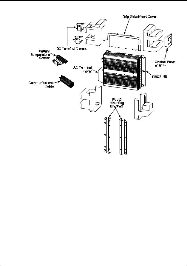
Figure 1. Inverter/Charger Components
vi |
Prosine 2.5/3.0 Installation & Operation Guide |

Warranty
Warranty
What does this warranty cover? This Limited Warranty is provided by Xantrex Technology, Inc. ("Xantrex") and covers defects in workmanship and materials in your Xantrex Prosine 2.5/3.0 Inverter/ Charger. This warranty lasts for a Warranty Period of 24 months from the date of purchase at point of sale to you, the original end user customer.
This Limited Warranty is transferable to subsequent owners but only for the unexpired portion of the Warranty Period.
What will Xantrex do? Xantrex will, at its option, repair or replace the defective product free of charge, provided that you notify Xantrex of the product defect within the Warranty Period, and provided that Xantrex through inspection establishes the existence of such a defect and that it is covered by this Limited Warranty.
Xantrex will, at its option, use new and/or reconditioned parts in performing warranty repair and building replacement products. Xantrex reserves the right to use parts or products of original or improved design in the repair or replacement. If Xantrex repairs or replaces a product, its warranty continues for the remaining portion of the original Warranty Period or 90 days from the date of the return shipment to the customer, whichever is greater. All replaced products and all parts removed from repaired products become the property of Xantrex.
Xantrex covers both parts and labor necessary to repair the product, and return shipment to the customer via a Xantrex-selected non-expedited surface freight within the contiguous United States and Canada. Alaska and Hawaii are excluded. Contact Xantrex Customer Service for details on freight policy for return shipments outside of the contiguous United States and Canada.
How do you get service? If your product requires troubleshooting or warranty service, contact your merchant. If you are unable to contact your merchant, or the merchant is unable to provide service, contact Xantrex directly at:
Phone: 1-800-670-0707 (toll free) 1-604-422-2777 (direct)
Fax: 1-604-420-2145
Email: CustomerService@xantrex.com
Direct returns may be performed according to the Xantrex Return Material Authorization Policy described in your product manual. For some products, Xantrex maintains a network of regional Authorized Service Centers. Call Xantrex or check our website to see if your product can be repaired at one of these facilities.
In any warranty claim, dated proof of purchase must accompany the product and the product must not have been disassembled or modified without prior written authorization by Xantrex.
Proof of purchase may be in any one of the following forms:
•The dated purchase receipt from the original purchase of the product at point of sale to the end user, or
•The dated dealer invoice or purchase receipt showing original equipment manufacturer (OEM) status, or
•The dated invoice or purchase receipt showing the product exchanged under warranty
What does this warranty not cover? This Limited Warranty does not cover normal wear and tear of the product or costs related to the removal, installation, or troubleshooting of the customer's electrical systems. This warranty does not apply to and Xantrex will not be responsible for any defect in or damage to:
Prosine 2.5/3.0 Installation & Operation Guide |
vii |
Disclaimer
a)the product if it has been misused, neglected, improperly installed, physically damaged or altered, either internally or externally, or damaged from improper use or use in an unsuitable environment;
b)the product if it has been subjected to fire, water, generalized corrosion, biological infestations, or input voltage that creates operating conditions beyond the maximum or minimum limits listed in the Xantrex product specifications including high input voltage from generators and lightning strikes;
c)the product if repairs have been done to it other than by Xantrex or its authorized service centers (hereafter "ASCs");
d)the product if it is used as a component part of a product expressly warranted by another manufacturer;
e)the product if its original identification (trade-mark, serial number) markings have been defaced, altered, or removed.
Disclaimer
Product
THIS LIMITED WARRANTY IS THE SOLE AND EXCLUSIVE WARRANTY PROVIDED BY XANTREX IN CONNECTION WITH YOUR XANTREX PRODUCT AND IS, WHERE PERMITTED BY LAW, IN LIEU OF ALL OTHER WARRANTIES, CONDITIONS, GUARANTEES, REPRESENTATIONS, OBLIGATIONS AND LIABILITIES, EXPRESS OR IMPLIED, STATUTORY OR OTHERWISE IN CONNECTION WITH THE PRODUCT, HOWEVER ARISING (WHETHER BY CONTRACT, TORT, NEGLIGENCE, PRINCIPLES OF MANUFACTURER'S LIABILITY, OPERATION OF LAW, CONDUCT, STATEMENT OR OTHERWISE), INCLUDING WITHOUT RESTRICTION ANY IMPLIED WARRANTY OR CONDITION OF QUALITY, MERCHANTABILITY OR FITNESS FOR A PARTICULAR PURPOSE. ANY IMPLIED WARRANTY OF MERCHANTABILITY OR FITNESS FOR A PARTICULAR PURPOSE TO THE EXTENT REQUIRED UNDER APPLICABLE LAW TO APPLY TO THE PRODUCT SHALL BE LIMITED IN DURATION TO THE PERIOD STIPULATED UNDER THIS LIMITED WARRANTY.
IN NO EVENT WILL XANTREX BE LIABLE FOR ANY SPECIAL, DIRECT, INDIRECT, INCIDENTAL OR CONSEQUENTIAL DAMAGES, LOSSES, COSTS OR EXPENSES HOWEVER ARISING WHETHER IN CONTRACT OR TORT INCLUDING WITHOUT RESTRICTION ANY ECONOMIC LOSSES OF ANY KIND, ANY LOSS OR DAMAGE TO PROPERTY, ANY PERSONAL INJURY, ANY DAMAGE OR INJURY ARISING FROM OR AS A RESULT OF MISUSE OR ABUSE, OR THE INCORRECT INSTALLATION, INTEGRATION OR OPERATION OF THE PRODUCT.
Exclusions
If this product is a consumer product, federal law does not allow an exclusion of implied warranties. To the extent you are entitled to implied warranties under federal law, to the extent permitted by applicable law they are limited to the duration of this Limited Warranty. Some states and provinces do not allow limitations or exclusions on implied warranties or on the duration of an implied warranty or on the limitation or exclusion of incidental or consequential damages, so the above limitation(s) or exclusion(s) may not apply to you. This Limited Warranty gives you specific legal rights. You may have other rights which may vary from state to state or province to province.
viii |
Prosine 2.5/3.0 Installation & Operation Guide |

Warranty
Warning: Limitations On Use
Please refer to your product user manual for limitations on uses of the product. Specifically, please note that the Xantrex Prosine 2.5/3.0 Inverter/Charger is not intended for use in connection with life support systems and Xantrex makes no warranty or representation in connection with any use of the product for such purposes.
Please note that the Xantrex Prosine 2.5/3.0 Inverter/Charger is not intended for use as an uninterruptible power supply and Xantrex makes no warranty or representation in connection with any use of the product for such purposes.
Return Material Authorization Policy
Before returning a product directly to Xantrex you must obtain a Return Material Authorization (RMA) number and the correct factory "Ship To" address. Products must also be shipped prepaid. Product shipments will be refused and returned at your expense if they are unauthorized, returned without an RMA number clearly marked on the outside of the shipping box, if they are shipped collect, or if they are shipped to the wrong location.
When you contact Xantrex to obtain service, please have your instruction manual ready for reference and be prepared to supply:
•The serial number of your product
•Information about the installation and use of the unit
•Information about the failure and/or reason for the return
•A copy of your dated proof of purchase
Return Procedure
1.Package the unit safely, preferably using the original box and packing materials. Please ensure that your product is shipped fully insured in the original packaging or equivalent. This warranty will not apply where the product is damaged due to improper packaging.
2.Include the following:
•The RMA number supplied by Xantrex Technology Inc clearly marked on the outside of the
box.
•A return address where the unit can be shipped. Post office boxes are not acceptable.
•A contact telephone number where you can be reached during work hours
•A brief description of the problem
3.Ship the unit prepaid to the address provided by your Xantrex customer service representative.
If you are returning a product from outside of the USA or Canada In addition to the above you MUST include return freight funds and are fully responsible for all documents, duties, tariffs, and deposits.
If you are returning a product to a Xantrex Authorized Service Center (ASC) A Xantrex return material authorization (RMA) number is not required. However, you must contact the ASC prior to returning the product or presenting the unit to verify any return procedures that may apply to that particular facility.
Prosine 2.5/3.0 Installation & Operation Guide |
ix |

Return Procedure
x |
Prosine 2.5/3.0 Installation & Operation Guide |

Contents
Important Safety Instructions. . . . . . . . . . . . . . . . . . . . . . . . . . . . . . . . . . . . . . . . . . .i Materials List . . . . . . . . . . . . . . . . . . . . . . . . . . . . . . . . . . . . . . . . . . . . . . . . . . . . . .iv Warranty. . . . . . . . . . . . . . . . . . . . . . . . . . . . . . . . . . . . . . . . . . . . . . . . . . . . . . . . . vii
Disclaimer. . . . . . . . . . . . . . . . . . . . . . . . . . . . . . . . . . . . . . . . . . . . . . . . . . . . . . . viii
Product . . . . . . . . . . . . . . . . . . . . . . . . . . . . . . . . . . . . . . . . . . . . . . . . . . . viii
Exclusions . . . . . . . . . . . . . . . . . . . . . . . . . . . . . . . . . . . . . . . . . . . . . . . . . . . . . . viii Warning: Limitations On Use . . . . . . . . . . . . . . . . . . . . . . . . . . . . . . . . . . . . . . . . .ix Return Material Authorization Policy . . . . . . . . . . . . . . . . . . . . . . . . . . . . . . . . . . . ix Return Procedure . . . . . . . . . . . . . . . . . . . . . . . . . . . . . . . . . . . . . . . . . . . . . . . . . . ix
Contents . . . . . . . . . . . . . . . . . . . . . . . . . . . . . . . . . . . . . . . . . . . . . . . . . . . . . . . . . .xi Section 1: Features. . . . . . . . . . . . . . . . . . . . . . . . . . . . . . . . . . . . . . . . . . . . . . . . . . 1
Battery Charger Features. . . . . . . . . . . . . . . . . . . . . . . . . . . . . . . . . . . . . . . . . . . . 1
Inverter Features . . . . . . . . . . . . . . . . . . . . . . . . . . . . . . . . . . . . . . . . . . . . . . . . . . 2
Section 2: Controls and Indicators. . . . . . . . . . . . . . . . . . . . . . . . . . . . . . . . . . . . . . 5
DIP Switch Panel . . . . . . . . . . . . . . . . . . . . . . . . . . . . . . . . . . . . . . . . . . . . . . . . . . 5
Accessory Jacks. . . . . . . . . . . . . . . . . . . . . . . . . . . . . . . . . . . . . . . . . . . . . . . . . . . 5
AC Bypass Selector . . . . . . . . . . . . . . . . . . . . . . . . . . . . . . . . . . . . . . . . . . . . . . . . 6
DC Terminals & Covers . . . . . . . . . . . . . . . . . . . . . . . . . . . . . . . . . . . . . . . . . . . . . 6
AC Terminals & Covers . . . . . . . . . . . . . . . . . . . . . . . . . . . . . . . . . . . . . . . . . . . . . 6
Standard LED Control Panel . . . . . . . . . . . . . . . . . . . . . . . . . . . . . . . . . . . . . . . . . 7
Battery Status Indicator . . . . . . . . . . . . . . . . . . . . . . . . . . . . . . . . . . . . . . . . 8
Faults Indicators & Reset Button . . . . . . . . . . . . . . . . . . . . . . . . . . . . . . . . . 8
Inverter Status Indicators and On/Off Button . . . . . . . . . . . . . . . . . . . . . . . . 9
Power Indicator. . . . . . . . . . . . . . . . . . . . . . . . . . . . . . . . . . . . . . . . . . . . . . 10
Charger Status Indicator and On/Off Button. . . . . . . . . . . . . . . . . . . . . . . . 10
Mounting and Installing the LED Control Panel . . . . . . . . . . . . . . . . . . . . . . . . . . 11
ACS Control Panel . . . . . . . . . . . . . . . . . . . . . . . . . . . . . . . . . . . . . . . . . . . . . . . . 12
Liquid Crystal Display . . . . . . . . . . . . . . . . . . . . . . . . . . . . . . . . . . . . . . . . . 13
Control Buttons . . . . . . . . . . . . . . . . . . . . . . . . . . . . . . . . . . . . . . . . . . . . . . 13
Menu Navigation Procedure . . . . . . . . . . . . . . . . . . . . . . . . . . . . . . . . . . . . 14
ACS Menu Tree . . . . . . . . . . . . . . . . . . . . . . . . . . . . . . . . . . . . . . . . . . . . . 14
AC Information Menu . . . . . . . . . . . . . . . . . . . . . . . . . . . . . . . . . . . . . . . . . 15
Battery Information Menu . . . . . . . . . . . . . . . . . . . . . . . . . . . . . . . . . . . . . . 16
Inverter Information Menu. . . . . . . . . . . . . . . . . . . . . . . . . . . . . . . . . . . . . . 16
Charger Information Menu . . . . . . . . . . . . . . . . . . . . . . . . . . . . . . . . . . . . . 17
Prosine 2.5/3.0 Installation & Operation Guide |
xi |

Contents
System Information Menu. . . . . . . . . . . . . . . . . . . . . . . . . . . . . . . . . . . . . . 18
Version Information Menu. . . . . . . . . . . . . . . . . . . . . . . . . . . . . . . . . . . . . . 19
Faults Display & Reset Button . . . . . . . . . . . . . . . . . . . . . . . . . . . . . . . . . . . . . . . 20
Inverter Status Indicators and On/Off Button . . . . . . . . . . . . . . . . . . . . . . . . . . . . 20
Power Indicator . . . . . . . . . . . . . . . . . . . . . . . . . . . . . . . . . . . . . . . . . . . . . . . . . . 21
Charger Status Indicator and On/Off Button . . . . . . . . . . . . . . . . . . . . . . . . . . . . 21
Mounting and Installing the ACS Control Panel . . . . . . . . . . . . . . . . . . . . . . . . . . 22
Battery Temperature Sensor . . . . . . . . . . . . . . . . . . . . . . . . . . . . . . . . . . . . . . . . 23
Section 3: Configuration . . . . . . . . . . . . . . . . . . . . . . . . . . . . . . . . . . . . . . . . . . . . 25
DIP Switch Settings . . . . . . . . . . . . . . . . . . . . . . . . . . . . . . . . . . . . . . . . . . . . . . . 25
ACS Configuration . . . . . . . . . . . . . . . . . . . . . . . . . . . . . . . . . . . . . . . . . . . . . . . . 28
User Configuration Items . . . . . . . . . . . . . . . . . . . . . . . . . . . . . . . . . . . . . . 28
Installer Configuration Items . . . . . . . . . . . . . . . . . . . . . . . . . . . . . . . . . . . . 28
ACS Configuration Considerations. . . . . . . . . . . . . . . . . . . . . . . . . . . . . . . . . . . . 29
AC (Shorepower) Configuration . . . . . . . . . . . . . . . . . . . . . . . . . . . . . . . . . 30
Battery Configuration . . . . . . . . . . . . . . . . . . . . . . . . . . . . . . . . . . . . . . . . . 31
Inverter Configuration . . . . . . . . . . . . . . . . . . . . . . . . . . . . . . . . . . . . . . . . . 33
Charger Configuration . . . . . . . . . . . . . . . . . . . . . . . . . . . . . . . . . . . . . . . . 34
System Configuration . . . . . . . . . . . . . . . . . . . . . . . . . . . . . . . . . . . . . . . . . 36
Section 4: Inverter/Charger Installation. . . . . . . . . . . . . . . . . . . . . . . . . . . . . . . . . 37
Safety Instructions . . . . . . . . . . . . . . . . . . . . . . . . . . . . . . . . . . . . . . . . . . . . . . . . 37 Installation Overview . . . . . . . . . . . . . . . . . . . . . . . . . . . . . . . . . . . . . . . . . . . . . . 37 Designing the Installation . . . . . . . . . . . . . . . . . . . . . . . . . . . . . . . . . . . . . . . . . . . 40 Tools and Materials Required. . . . . . . . . . . . . . . . . . . . . . . . . . . . . . . . . . . . . . . . 42 Where to Install the Prosine Inverter/Charger . . . . . . . . . . . . . . . . . . . . . . . . . . . 42 Mounting the Prosine Inverter/Charger . . . . . . . . . . . . . . . . . . . . . . . . . . . . . . . . 44 AC Cabling . . . . . . . . . . . . . . . . . . . . . . . . . . . . . . . . . . . . . . . . . . . . . . . . . . . . . . 45
Recommended Wire Size vs Breaker Rating . . . . . . . . . . . . . . . . . . . . . . . 45 AC and DC Wiring Separation . . . . . . . . . . . . . . . . . . . . . . . . . . . . . . . . . . 45 AC Output Neutral-to-Ground Bonding. . . . . . . . . . . . . . . . . . . . . . . . . . . . 45
AC Disconnect and Overload Protection . . . . . . . . . . . . . . . . . . . . . . . . . . . . . . . 45 DC Cabling . . . . . . . . . . . . . . . . . . . . . . . . . . . . . . . . . . . . . . . . . . . . . . . . . . . . . . 46
DC Over-Current Protection . . . . . . . . . . . . . . . . . . . . . . . . . . . . . . . . . . . . 46
Recommended DC Cable Sizes For Proper Operation . . . . . . . . . . . . . . . . . . . . 47
DC Disconnect . . . . . . . . . . . . . . . . . . . . . . . . . . . . . . . . . . . . . . . . . . . . . . 47 Battery Cable Routing. . . . . . . . . . . . . . . . . . . . . . . . . . . . . . . . . . . . . . . . . 47 DC Cabling Connections . . . . . . . . . . . . . . . . . . . . . . . . . . . . . . . . . . . . . . 47 DC Cabling Procedure . . . . . . . . . . . . . . . . . . . . . . . . . . . . . . . . . . . . . . . . 48 DC Grounding. . . . . . . . . . . . . . . . . . . . . . . . . . . . . . . . . . . . . . . . . . . . . . . 49
Connecting the Battery Temperature Sensor . . . . . . . . . . . . . . . . . . . . . . . . . . . . 49
Mounting Options . . . . . . . . . . . . . . . . . . . . . . . . . . . . . . . . . . . . . . . . . . . . 49
xii |
Prosine 2.5/3.0 Installation & Operation Guide |

Contents
Mounting to the Negative Battery Terminal . . . . . . . . . . . . . . . . . . . . . . . . 50 Mounting to the Side of the Battery Case . . . . . . . . . . . . . . . . . . . . . . . . . . 51
Typical System Diagrams . . . . . . . . . . . . . . . . . . . . . . . . . . . . . . . . . . . . . . . . . . . 52
Residential Backup System . . . . . . . . . . . . . . . . . . . . . . . . . . . . . . . . . . . . 52 Recreational Vehicle System . . . . . . . . . . . . . . . . . . . . . . . . . . . . . . . . . . . 53 Residential Solar and Wind System . . . . . . . . . . . . . . . . . . . . . . . . . . . . . . 54
Section 5: Operation . . . . . . . . . . . . . . . . . . . . . . . . . . . . . . . . . . . . . . . . . . . . . . . 55
Prosine Inverter Load Sense Mode . . . . . . . . . . . . . . . . . . . . . . . . . . . . . . . . . . . 56 Operating Limits for Inverter Operation . . . . . . . . . . . . . . . . . . . . . . . . . . . . . . . . 56
Section 6: Multistage Charging . . . . . . . . . . . . . . . . . . . . . . . . . . . . . . . . . . . . . . . 59
Charging Profile . . . . . . . . . . . . . . . . . . . . . . . . . . . . . . . . . . . . . . . . . . . . . . . . . . 59
Bulk Charge . . . . . . . . . . . . . . . . . . . . . . . . . . . . . . . . . . . . . . . . . . . . . . . . 59 Absorption Charge . . . . . . . . . . . . . . . . . . . . . . . . . . . . . . . . . . . . . . . . . . . 59 Float Charge . . . . . . . . . . . . . . . . . . . . . . . . . . . . . . . . . . . . . . . . . . . . . . . . 60 Equalization Charge . . . . . . . . . . . . . . . . . . . . . . . . . . . . . . . . . . . . . . . . . . 60
Operation in Charger Mode . . . . . . . . . . . . . . . . . . . . . . . . . . . . . . . . . . . . . . . . . 61 Operation in Equalization Mode . . . . . . . . . . . . . . . . . . . . . . . . . . . . . . . . . . . . . . 61
Equalization Procedure. . . . . . . . . . . . . . . . . . . . . . . . . . . . . . . . . . . . . . . . 61 Adjustable Charger Mode Settings . . . . . . . . . . . . . . . . . . . . . . . . . . . . . . . 62 Battery Charging Times . . . . . . . . . . . . . . . . . . . . . . . . . . . . . . . . . . . . . . . 63
Operating Limits for Charger Operation . . . . . . . . . . . . . . . . . . . . . . . . . . . . . . . . 63
Battery Charging and Equalization Guide. . . . . . . . . . . . . . . . . . . . . . . . . . 64
Section 7: Batteries . . . . . . . . . . . . . . . . . . . . . . . . . . . . . . . . . . . . . . . . . . . . . . . . 67
Terminology . . . . . . . . . . . . . . . . . . . . . . . . . . . . . . . . . . . . . . . . . . . . . . . . . . . . . 67
Types . . . . . . . . . . . . . . . . . . . . . . . . . . . . . . . . . . . . . . . . . . . . . . . . . . . . . . . . . . 67
Starting Batteries . . . . . . . . . . . . . . . . . . . . . . . . . . . . . . . . . . . . . . . . . . . . 68
Deep-Cycle Batteries . . . . . . . . . . . . . . . . . . . . . . . . . . . . . . . . . . . . . . . . . 68
Sealed Gel Cell. . . . . . . . . . . . . . . . . . . . . . . . . . . . . . . . . . . . . . . . . . . . . . 69
Environment . . . . . . . . . . . . . . . . . . . . . . . . . . . . . . . . . . . . . . . . . . . . . . . . 69
Location . . . . . . . . . . . . . . . . . . . . . . . . . . . . . . . . . . . . . . . . . . . . . . . . . . . 69
Enclosures . . . . . . . . . . . . . . . . . . . . . . . . . . . . . . . . . . . . . . . . . . . . . . . . . 69
Temperature . . . . . . . . . . . . . . . . . . . . . . . . . . . . . . . . . . . . . . . . . . . . . . . . 69
Battery Bank Sizing . . . . . . . . . . . . . . . . . . . . . . . . . . . . . . . . . . . . . . . . . . . . . . . 70
Estimating Battery Requirements. . . . . . . . . . . . . . . . . . . . . . . . . . . . . . . . . . . . . 70
Battery Bank Sizing Example & Worksheet . . . . . . . . . . . . . . . . . . . . . . . . 71
Monthly Battery Maintenance. . . . . . . . . . . . . . . . . . . . . . . . . . . . . . . . . . . . . . . . 73
Cleaning Batteries . . . . . . . . . . . . . . . . . . . . . . . . . . . . . . . . . . . . . . . . . . . 73
Preparation . . . . . . . . . . . . . . . . . . . . . . . . . . . . . . . . . . . . . . . . . . . . . . . . . 73
Attire . . . . . . . . . . . . . . . . . . . . . . . . . . . . . . . . . . . . . . . . . . . . . . . . . . . . . . 73
Tools . . . . . . . . . . . . . . . . . . . . . . . . . . . . . . . . . . . . . . . . . . . . . . . . . . . . . . 73
Prosine 2.5/3.0 Installation & Operation Guide |
xiii |

Contents
Equipment. . . . . . . . . . . . . . . . . . . . . . . . . . . . . . . . . . . . . . . . . . . . . . . . . . 74
Supplies . . . . . . . . . . . . . . . . . . . . . . . . . . . . . . . . . . . . . . . . . . . . . . . . . . . 74
Procedure . . . . . . . . . . . . . . . . . . . . . . . . . . . . . . . . . . . . . . . . . . . . . . . . . . 74
Cables. . . . . . . . . . . . . . . . . . . . . . . . . . . . . . . . . . . . . . . . . . . . . . . . . . . . . 75
Cabling & Hook-up Configurations . . . . . . . . . . . . . . . . . . . . . . . . . . . . . . . . . . . . 75
Parallel Connection. . . . . . . . . . . . . . . . . . . . . . . . . . . . . . . . . . . . . . . . . . . 75
Series Connection . . . . . . . . . . . . . . . . . . . . . . . . . . . . . . . . . . . . . . . . . . . 76
Series – Parallel Connection . . . . . . . . . . . . . . . . . . . . . . . . . . . . . . . . . . . 77
Appendix A: Specifications . . . . . . . . . . . . . . . . . . . . . . . . . . . . . . . . . . . . . . . . . . 79
Charger Output Voltages . . . . . . . . . . . . . . . . . . . . . . . . . . . . . . . . . . . . . . 80 Prosine 2.5/3.0 Chassis Dimensions . . . . . . . . . . . . . . . . . . . . . . . . . . . . . 81 Prosine 2.5/3.0 Chassis Dimensions with Brackets . . . . . . . . . . . . . . . . . . 82
Appendix B: Inverter Applications . . . . . . . . . . . . . . . . . . . . . . . . . . . . . . . . . . . . 85
Resistive Loads . . . . . . . . . . . . . . . . . . . . . . . . . . . . . . . . . . . . . . . . . . . . . . . . . . 85
Inductive Loads . . . . . . . . . . . . . . . . . . . . . . . . . . . . . . . . . . . . . . . . . . . . . . . . . . 85
Problem Loads in Load Sense . . . . . . . . . . . . . . . . . . . . . . . . . . . . . . . . . . . . . . . 85
Appendix C: Troubleshooting . . . . . . . . . . . . . . . . . . . . . . . . . . . . . . . . . . . . . . . . 87
What to do if a problem occurs. . . . . . . . . . . . . . . . . . . . . . . . . . . . . . . . . . . . . . . 87 Error Code Displays and What They Mean . . . . . . . . . . . . . . . . . . . . . . . . . . . . . 88
Control Panel . . . . . . . . . . . . . . . . . . . . . . . . . . . . . . . . . . . . . . . . . . . . . . . 88 Advanced Control System (ACS) . . . . . . . . . . . . . . . . . . . . . . . . . . . . . . . . 88
Error Code Table . . . . . . . . . . . . . . . . . . . . . . . . . . . . . . . . . . . . . . . . . . . . . . . . . 89
xiv |
Prosine 2.5/3.0 Installation & Operation Guide |

Section 1: Features
Congratulations on your purchase of the Prosine inverter/charger. The Prosine inverter/charger uses advanced high-frequency switching technology in the power conversion process. The circuits are similar to those used in power supplies for computers and other modern electronic equipment. This technology offers several benefits:
•Light weight: for easy installation
•Quiet operation: no transformer buzz
•Clean DC output: filtered output for ideal battery charging
•High surge capability: for hard-to-start AC loads
All Prosine inverter/chargers are approved for general use including residential, recreational vehicle, marine, and photovoltaic applications based upon Canadian Standards Association (CSA), Underwriter Laboratories (UL), and other regulatory agency standards. Prosine inverter/chargers meet the stringent requirements of CSA 107.1 “General Use Power Supplies,” UL 458 “Power Converters/Inverters and Power Converter/Inverter Systems for Land Vehicles and Marine Crafts,” UL1741 “Power Conditioning Units for Use in Residential Photovoltaic Systems,” and other standards.
Battery Charger Features
Dead Battery Charging Starts recharging batteries even if the battery voltage is near zero.
Power Factor Correction High power factor charging results in faster battery charging because lower AC current is required from your generator or shorepower. When the AC source has limited capacity, the charger leaves more current available for other AC loads on the circuit. On a 15-ampere shorepower circuit, a Prosine charger delivers as much as 100 amps of DC current to the battery, while non power-factor-corrected chargers typically can deliver only about 70 amps.
Automatic Three-Stage Charging Whenever AC power is supplied to the Prosine inverter/charger, the “smart” charging capability of the Prosine provides a three-stage charge to quickly bring back deep-cycle batteries to their full charge. Using microprocessor control, the Prosine precisely regulates the voltage and current delivered to the battery, accurately charging the battery without risk of overcharging and battery damage. Depleted batteries are taken through the recommended “Bulk”, “Absorption”, and “Float” stages. The charging algorithm used in the Prosine inverter/charger is based on the same charge cycle algorithm used in Xantrex’s proven Truecharge battery charger line.
Manual Equalization Charging The Prosine inverter/charger enables you to initiate an equalization charge to optimize your battery capacity and rejuvenate your batteries. Equalization (for flooded batteries only) helps reduce sulfation and extends battery life.
Battery Temperature Sensor Since battery temperature is a key factor in correct charging, the charging formula must be adjusted (automatically and in real time) according to the actual battery temperature to ensure that batteries are fully, but not over charged. For this reason, Xantrex has included a battery temperature sensor with your Prosine inverter/charger and has temperaturecompensated the charge algorithm.
Prosine 2.5/3.0 Installation & Operation Guide |
1 |

Inverter Features
Battery Temperature Shut Down When using the battery-temperature sensor, the charger will shut down if it detects excessively high or low battery temperatures. If battery temperature exceeds 50°C (122°F), or falls below -15°C (5°F), the charger will shut down.
Adjustable Maximum AC Input Current This feature protects against nuisance tripping of AC circuit breakers on the utility or generator AC supply. You can set the maximum AC input current to 8, 12, 16, or 24 amps to prevent 10, 15, 20, and 30-amp (respectively) circuit breakers from unnecessarily tripping as AC load demands approach their current rating. You can set the maximum AC input current in one (1) amp increments using the ACS control panel. The Prosine automatically reduces its charging current to attempt to keep the sum of all loads from exceeding this setting. The Prosine has no control over the loads you apply, so if nuisance-tripping still occurs, try removing one or more of your AC loads.
Inverter Features
Automatic Transfer Switch When utility AC power fails or is disconnected from the unit, or falls below 90 volts, the Prosine will automatically begin inverting and provide AC power from your batteries within 20 milliseconds; fast enough to keep a computer running. When utility AC is restored, the inverter will sample the AC power for about 8 seconds, synchronize to the AC waveform, and automatically switch your loads to utility power. It also returns to charging the batteries.
Automatic Waveform Regulation The Prosine inverter/charger monitors and regulates the AC waveform when inverting, delivering a true sinewave with typically only 1% total harmonic distortion (THD). This is usually cleaner than generator and utility waveforms.
High Surge Capacity The Prosine inverter will deliver up to 4000 watts of power for up to five seconds to start large motors and other inductive loads that require high power levels to start. The Prosine 2.5 will deliver 2500 watts (21-amps RMS) continuously, while the Prosine 3.0 delivers up to 3000 watts (25-amps RMS) continuously.
Load Sense Prosine inverters reduce power consumption during idle periods to conserve battery capacity by “searching” for loads that exceed a specified threshold. When a load is detected, the inverter ‘turns-on’ and delivers full voltage. When no load is detected, the inverter ‘stands-by,’ consuming less than three watts of power. The threshold can be set at 10, 25, or 50 watts (10 to 1401 watts using the ACS Control Panel), or disabled by setting it to zero (0).
Integral Protective Circuitry All Prosine inverter/chargers feature built-in protective circuitry that guards against damage to the inverter and your AC equipment due to high battery voltage, low battery voltage, AC overload, and high temperature conditions. This protective circuitry includes:
Automatic Low Battery Shut Down The Prosine inverter protects your batteries from damage by over-discharge by shutting down when battery voltage drops to 10.00 volts for 12-volt units, and 20 volts for 24-volt units. The unit will resume inverting when battery voltage exceeds 12.3 volts for 12volt models, and 24.6-volts for 24-volt models.
Automatic High Battery Shut Down The Prosine inverter/charger protects itself from damage from excessive battery voltages by shutting down when battery voltage reaches 16-volts for 12-volt units, and 32-volts for 24-volt units. When battery voltage falls to 15.5-volts for 12-volt units, and 31-volts for 24-volt units, the unit will automatically restart.
2 |
Prosine 2.5/3.0 Installation & Operation Guide |

Section 1: Features
Over-Current Protection When the AC loads connected to the Prosine inverter/charger exceed 50 amps, the inverter will instantaneously reduce the output voltage until the loads on the inverter are reduced. If the overload continues, the inverter will shut down. The unit will automatically restart after a calculated recovery time.
High-Temperature Shut Down When the inverter detects a high-temperature condition internally, the inverter will shut down. When the internal temperature cools by at least 6°C (11°F) the unit will automatically restart.
Audible Fault Alarm The Prosine inverter/charger features a user-enable audible alarm to alert you in the event of a fault condition. The audible alarm is accompanied by blinking LEDs (on the control panel) or by a fault code display (on the ACS control panel). There are four fault conditions at which the audible alarm will sound:
•Battery high-voltage
•Battery low-voltage
•System over-temperature
•Communication error or temporary fault
Visual Fault Code Display If an error occurs, the Prosine inverter/charger control panel will display an error code that you can use to determine the cause of the error. Three LEDs will flash on the standard control panel to describe the error. On the ACS control panel, the error code will be displayed on the LCD display. A table of fault codes and likely causes, along with corrective measures to take, is provided in “Appendix C: Troubleshooting”.
Prosine 2.5/3.0 Installation & Operation Guide |
3 |
Inverter Features
4 |
Prosine 2.5/3.0 Installation & Operation Guide |

Section 2: Controls and Indicators
Prosine 2.5 inverter/chargers feature DC input and output connectors, an AC terminal block, a DIP switch panel for custom configuration, three accessory jacks, an LED control panel for the PS2.5 and an ACS panel for PS3.0, an LCD control panel, a cover for the AC connector block. The LCD control panel is optional on the PS2.5 and standard on the PS3.0. DC terminal covers come standard with both units. A replacement AC cover with a GFCI outlet is available as an accessory option for both the PS2.5 and PS3.0.
Figure 2. Prosine Chassis Side and Bottom Views
DIP Switch Panel
The DIP switch panel consists of two small, eightposition up-down switches located under a cover on the side of the Prosine inverter/charger: SW1 and SW2.
These switches are used to configure the Battery Type, Battery Temperature, Load Sensing, Audible Signal, AC Service Rating, and Battery Size user-selectable options. See “Section 3: Configuration” on page 25 for configuration instructions.
Accessory Jacks
Three accessory jacks are provided on the side of Prosine inverter/charger: a battery temperature sensor jack (labeled BATT TEMP) and two Remote Output jacks. The battery temperature sensor reports battery temperature to the charger to
Prosine 2.5/3.0 Installation & Operation Guide |
5 |
AC Bypass Selector
optimize the charging profile. The remote output jacks enable you to remotely mount the standard and/or the ACS control panels, described later in this section of this manual.
AC Bypass Selector
The small slide switch located between the Batt Temp jack and the Remote Output jacks is the AC Bypass selector switch. The default position of this switch is On. In the On position, the inverter/ charger operates as programmed. When the switch is in the Bypass position, the inverter/charger is Off, and AC current bypasses the inverter/charger to supply
the AC loads directly.
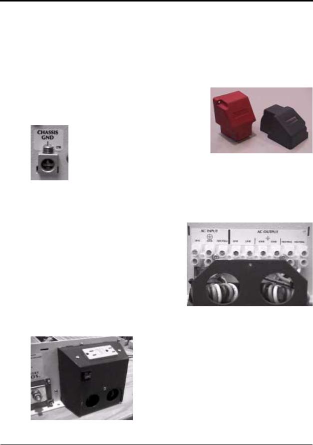
DC Terminals & Covers
The DC cabling connectors are located on the bottom of the Prosine inverter/charger. Each connector is an M10 x 1.5 stainless steel stud and nut. The studs are about 1-inch long and
approximately 3/8-inch in diameter. Use a 17mm (~11/16-inch) wrench. Two colorcoded covers, a red one for the positive terminal and a black one for the negative terminal, are provided for preventing accidental contact with these connectors after installation.
Adjacent to the DC terminals is the chassis ground lug. The chassis ground lug provides a ground path for DC fault current from the inverter/charger chassis to ensure your battery fuse opens in the event of a fault.
AC Terminals & Covers
On the bottom of the Prosine inverter/charger, alongside the DC connectors, a nine-position terminal block is provided for attaching AC cabling to the unit. The terminal block is divided into ACInput and AC-Output sections. One terminal each is
provided for the AC Line-In (Hot) cable, the AC Neutral-In cable, and the AC Ground-In (GND) cable. Two terminals each are provided for the AC Line-Out cable, the AC Neutral-Out cable, and the
AC Ground-Out cable. All are clearly labeled. The AC Line cable usually has a black insulator, the AC Neutral generally has a white insulator, and the AC Ground cable generally has either a green insulator, or no insulator at all.
Adjacent to the AC terminal block is a black bracket with two 1-inch diameter holes in it. This bracket is provided for attaching cable clamps (strain reliefs) or conduit. A cover is provided that slides into the end plate of the inverter and attaches to the strain-relief bracket. This cover is also available with an optional AC duplex GFCI outlet and 15-amp circuit protector.
6 |
Prosine 2.5/3.0 Installation & Operation Guide |
Section 2: Controls and Indicators
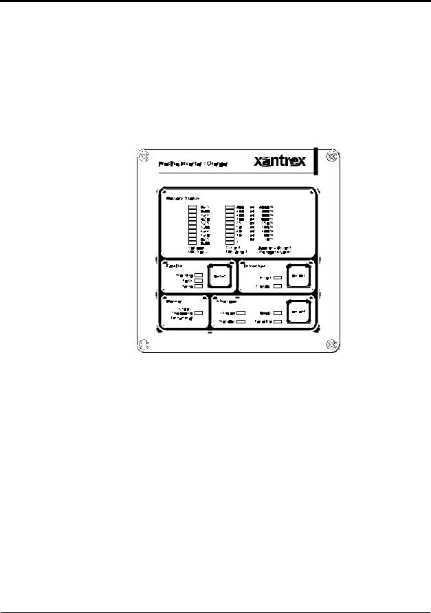
Standard LED Control Panel
The Prosine inverter/charger is supplied with a control panel that can be mounted into an instrument panel, bulkhead or wall. The standard control panel is used to report information about Prosine operating parameters and the external AC and DC power sources connected to it. The standard control panel has five separate functional divisions: the Battery Status LED display, the Faults Display and Reset Button, the Inverter Status Indicator and On/Off Control Button, the Shorepower Indicator, and the Charger Status Display and On/Off Control. These functional divisions are shown in the following illustration.
Figure 3. Standard LED Control Panel Display
Prosine 2.5/3.0 Installation & Operation Guide |
7 |
Standard LED Control Panel
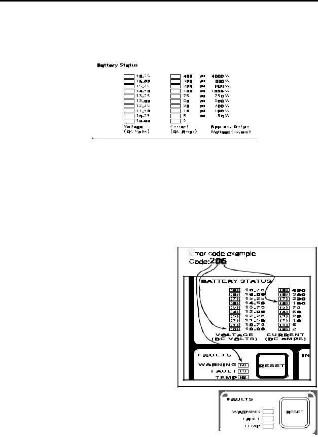
Battery Status Indicator
The Battery Status LED Display includes two vertical series of LEDs that indicate the battery voltage and current. A conversion table enables you to estimate the AC output from the inverter by the DC current.
Battery Voltage Indicator This indicator reports the battery voltage at the input terminals of the Prosine inverter/charger. At low currents, the indicator is very accurate. At high currents, the indicated voltage will be somewhat lower than the actual battery voltage due to voltage drop across the cables between battery and inverter. The range of the battery voltage indicator is from 10.0 to 16.75 volts DC. The LEDs do not light until the voltage level exceeds the value printed alongside the LED.
Battery Current Indicator This indicator reports the current drawn by the Prosine inverter/charger from the batteries. It does not indicate current drawn by other loads connected to the batteries. High current loads (over 200A) are displayed by yellow LEDs. The LEDs do not light until the current level exceeds the value printed alongside the LED.
Error Code Display When an error occurs, either the Warning, the Fault, or the Temp LED will be lighted, as well as one of the Battery Voltage LEDs, and one of the Battery Current LEDs. These three LEDs indicate an error code that you can look up on the Error. Code table in “Appendix C: Troubleshooting” to assist in determining the nature of the error In the example at right, the Warning, 10V, and 100A LEDs are flashing, and the error code indicated is derived from the value shown in parenthesis, in this case: 206. Look in the tables in “Appendix C: Troubleshooting” to determine the meaning of the code.
Faults Indicators & Reset Button
Warning LED This LED flashes on-and-off for the duration of any error condition, accompanied by an audible alarm if the alarm is enabled.
|
|
|
|
|
|
|
|
|
|
|
|
|
|
|
|
|
|
8 |
Prosine 2.5/3.0 Installation & Operation Guide |
||||
Section 2: Controls and Indicators
Fault LED This LED flashes on-and-off during an error condition from which the unit will automatically recover and restart when the condition is remedied. The FAULT LED will be lighted steadily when any error occurs from which the inverter/charger cannot automatically recover. It is usually necessary to disconnect the AC or DC supply to recover from this type of error. An error condition is accompanied by an audible alarm if the alarm is enabled.
Temp LED This LED flashes on-and-off to indicate that the internal temperature of the Prosine inverter/charger is too high and the unit has shutdown. When the internal temperature of the unit cools sufficiently, the inverter/charger will automatically restart. The audible alarm that accompanies this condition (if enabled) will also be silenced upon auto-restart.
Reset Button The RESET button on the Faults panel has two functions: pressed and released, it will silence the audible alarm which, if enabled, will sound an insistent intermittent tone anytime an error condition occurs, which can be looked up in a table to determine the nature of the error. Press and hold the RESET button to display error codes. Error codes are listed in an Appendix to this manual.
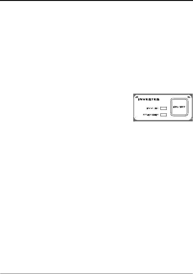
Inverter Status Indicators and On/Off Button
Invert LED When the green LED labeled INVERT is flashing,
shorepower is not present, Load Sense is enabled, and no AC loads exceed the Load Sense threshold. The inverter is not
producing AC power from the batteries. When the INVERT LED is lighted steadily, shorepower is not present and the
inverter is producing AC power from the batteries. The INVERT LED is not lighted when shorepower is present.
Standby LED When the amber LED labeled STANDBY is lighted steadily, shorepower is present and the inverter will pass AC power through to any AC loads that may be present.
If shorepower should fail or be removed while the inverter is in Standby mode, the inverter will automatically begin to produce AC power from the batteries, and the INVERT LED will be lighted.
On/Off Button. A button labeled ON/OFF is provided adjacent to the INVERT and STANDBY LEDs. When pressed, this button switches the inverter from On to Standby mode. Use in conjunction with the charger’s ON/OFF button to set the startup inverter/charger mode. See “Section 3: Configuration‚” on page 25 for instructions on how to set the startup inverter/charger mode.
Prosine 2.5/3.0 Installation & Operation Guide |
9 |
Standard LED Control Panel
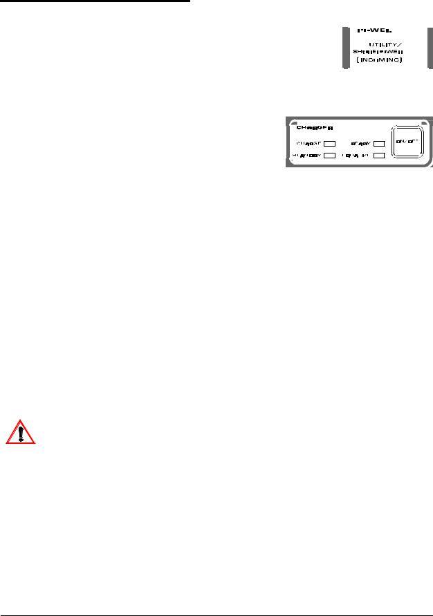
Power Indicator
A green LED labeled UTILITY/SHOREPOWER (INCOMING) lights whenever AC power is supplied to the AC INPUT connectors on the inverter/charger. Throughout this manual, the term “shorepower” refers to the presence of AC power at the AC INPUT connectors, regardless of the source of the power: from the utility grid (power company), a generator, or any other source.
Charger Status Indicator and On/Off
Button
The Charger Status Indicator includes four LEDs: a green LED labeled CHARGE; a green LED labeled READY; an amber LED labeled STANDBY; and an amber LED labeled EQUALIZE. A charger ON/OFF button is also provided.
Charge LED The green CHARGE LED lights when the Prosine charger is in Bulk or Absorption charging mode. A discussion of the Prosine three-stage charging profile is found in the “Charging Profile” section of this manual (see page 59).
Ready LED The green READY LED lights when the charging cycle has been completed, and the charger is in Float charging mode.
Standby LED The amber STANDBY LED lights when the charger is enabled awaiting AC power. When shorepower becomes available, the charger will begin charging, the STANDBY LED will be extinguished, and the CHARGE LED will be lighted.
Equalize LED The amber EQUALIZE LED lights when the battery equalization has been requested, and the Prosine is in Charge mode. An equalization charge cycle will commence after fully charging the batteries, and both the EQUALIZE LED and the CHARGE LED will flash on-and-off. See “Section 6: Multistage Charging” on page 59 for more information about equalization.
On/Off Button The charger ON/OFF button switches the charger between charger standby mode, On, and Off. In standby mode, the charger begins charging automatically when AC shorepower is available. In charge mode, press and hold this button for 5 seconds to request an equalize charge. Equalize mode will not begin until the batteries are fully charged.
CAUTION Disconnect DC loads on the batteries during equalization to prevent damage to them by the high voltages encountered during equalization. Equalization must be monitored to prevent battery damage. Refer to “Section 6: Multistage Charging” for more details.
10 |
Prosine 2.5/3.0 Installation & Operation Guide |

Section 2: Controls and Indicators
Mounting and Installing the LED Control Panel
You can install the LED Control Panel in a convenient location up to 50-feet from the Prosine inverter/ charger unit. This can be extended up to 100-feet with an appropriate extension cable of the same type.
For flush mount installation onto a wall, bulkhead, or panel, the remote panel requires an opening with the measurements of 4 1/8 inches by 4 1/8 inches (10.5cm by 10.5cm). Be sure that there is no wiring or other obstruction within the wall before making an opening. The LED Control Panel requires approximately 2 inches (5cm) of free space within the wall to accommodate its depth. Follow the steps shown below:
1.Select an appropriate location that is dry, not subject to corrosive or explosive fumes, and otherwise appropriate for mounting an electronic device.
2.Hold the control panel faceplate flush against the wall, bulkhead or panel and mark around the outside edge of the faceplate with a pencil.
3.Mark the location of the four mounting holes at each corner.
4.Remove the faceplate and mark a line 7/16-inch inside each of the four perimeter lines that you marked previously.
5.Drill an access hole at each corner of the resulting small square, large enough to allow you to insert a jigsaw blade. Place your drill bit so that the finished hole will not extend beyond the 4 1/8-inch by 4 1/8-inch square you marked on the bulkhead.
6.Use your jigsaw to cut between the holes you just drilled, and remove the material you just cut out. Blow out any waste residue from the cutting and drilling.
7.Route the telephone-type connector cable from your inverter/charger and the control panel and plug it into the control panel only.
8.Insert the control panel into the bulkhead and secure with appropriate fasteners.
9.Insert the other end of the connector cable it one of the RJ-11 connectors marked “Remote Output.”
10.Secure the EMI bead attached to the communications cable to a location close to the inverter/charger. The EMI bead reduces interference from the inverter on the control panel. Securing it prevents accidental disconnect of the remote panel.
If you purchased the ACS Panel as an accessory to be used with your Prosine 2.5, the ACS Panel and standard supplied panel can both be used at the same time. Either connect the standard panel to the OUTPUT jack on the back of the ACS Panel, or connect the standard panel to the REMOTE output connector jack on the side of the Prosine inverter/charger. The standard panel can then be mounted close by the Prosine unit for system monitoring in that location and the ACS Panel can be mounted remotely in some other area where you want more detailed operating information and control capability.
Prosine 2.5/3.0 Installation & Operation Guide |
11 |
ACS Control Panel
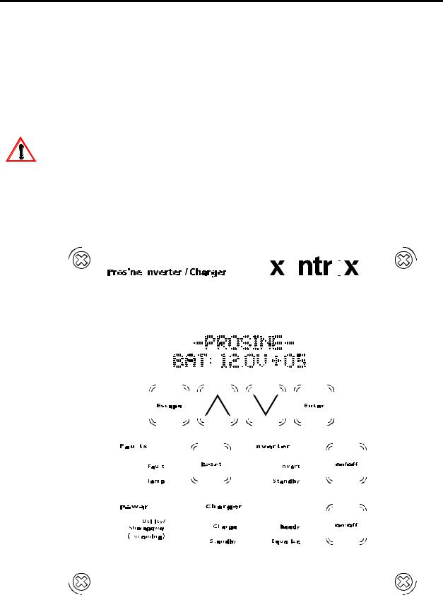
ACS Control Panel
The Advanced Control System (ACS) panel features a two-line 16-character liquid crystal display (LCD) that enables you to monitor and control your Prosine inverter/charger from a remote location. It comes standard with a 50-foot (15-metre) four-conductor telephone cord. The ACS control panel provides you with a finer degree of both monitoring and operating control over the standard control panel. If you purchased a Prosine 3.0, it comes with the ACS panel in place of the standard panel. The digital readout of the ACS gives you a detailed display of many parameters for the system, while the menu structure allows advanced configuration as well as the convenience to change system settings when you need to.
CAUTION Configuration settings made with the ACS panel will override settings made by configuring the DIP switches on the side of the chassis.
The ACS Panel has a backlight to facilitate reading. The backlight for the LCD panel illuminates when any key on the ACS is pressed. The backlight will remain on for one minute after the last key press, or after a warning has been displayed.
|
|
|
|
|
|
|
|
|
|
|
|
|
|
|
|
|
|
|
|
|
|
|
|
|
|
|
|
|
|
|
|
|
|
|
|
|
|
|
|
|
|
|
|
|
|
|
|
|
|
|
|
|
|
|
|
|
|
|
|
|
|
|
|
|
|
|
|
|
|
|
|
|
|
|
|
|
|
|
|
|
|
|
|
|
|
|
|
|
|
|
|
|
|
|
|
|
|
|
|
|
|
|
|
|
|
|
|
|
|
|
|
|
|
|
|
|
|
|
|
|
|
|
|
|
|
|
|
|
|
|
|
|
|
|
|
|
|
|
|
|
|
|
|
|
|
|
|
|
|
|
|
|
|
|
|
|
|
|
|
|
|
|
|
|
|
|
|
|
|
|
|
|
|
|
|
|
|
|
|
|
|
|
|
|
|
|
|
|
|
|
|
|
|
|
|
|
|
|
|
|
|
|
|
|
|
|
|
|
|
|
|
|
|
|
|
|
|
|
|
|
|
|
|
|
|
|
|
|
|
|
|
|
|
|
|
|
|
|
|
|
|
|
|
|
|
|
|
|
|
|
|
|
|
|
|
|
|
|
|
|
|
|
|
|
|
|
|
|
|
|
|
|
|
|
|
|
|
|
|
|
|
|
|
|
|
|
|
|
|
|
|
|
|
|
|
|
|
|
|
|
|
|
|
|
|
|
|
|
|
|
|
|
|
|
|
|
|
|
|
|
|
|
|
|
|
|
|
|
|
|
|
|
|
|
|
|
|
|
|
|
|
|
|
|
|
|
|
|
|
|
|
|
|
|
|
|
|
|
|
|
|
|
|
|
|
|
|
|
|
|
|
|
|
|
|
|
|
|
|
|
|
|
|
|
|
|
|
|
|
|
|
|
|
|
|
|
|
|
|
|
|
|
|
|
|
|
|
|
|
|
|
|
|
|
|
|
|
|
|
|
|
|
|
|
|
|
|
|
|
|
|
|
|
|
|
|
|
|
|
|
|
|
|
|
|
|
|
|
|
|
|
|
|
|
|
|
|
|
|
|
|
|
|
|
|
|
|
|
|
|
|
|
|
|
|
|
|
|
|
|
|
|
|
|
|
|
|
|
|
|
|
|
|
|
|
|
|
|
|
|
|
|
|
|
|
|
|
|
|
|
|
|
|
|
|
|
|
|
|
|
|
|
|
|
|
|
|
|
|
|
|
|
|
|
|
|
|
|
|
|
|
|
|
|
|
|
|
|
|
|
|
|
|
|
|
|
|
|
|
|
|
|
|
|
|
|
|
|
|
|
|
|
|
|
|
|
|
|
|
|
|
|
|
|
|
|
|
|
|
|
|
|
|
|
|
|
|
|
|
|
|
|
|
|
|
|
|
|
|
|
|
|
|
|
|
|
|
|
|
|
|
|
|
|
|
|
|
|
|
|
|
|
|
|
|
|
|
|
|
|
|
|
|
|
|
|
|
|
|
|
|
|
|
|
|
|
|
|
|
|
|
|
|
|
|
|
|
|
|
|
|
|
|
|
|
|
|
|
|
|
|
|
|
|
|
|
|
|
|
|
|
|
|
|
|
|
|
|
|
|
|
|
|
|
|
|
|
|
|
|
|
|
|
|
|
|
|
|
|
|
|
|
|
|
|
|
|
|
|
|
|
|
|
|
|
|
|
|
|
|
|
|
|
|
|
|
|
|
|
|
|
|
|
|
|
|
|
|
|
|
|
|
|
|
|
|
|
|
|
|
|
|
|
|
|
|
|
|
|
|
|
|
|
|
|
|
|
|
|
|
|
|
|
|
|
|
|
|
|
|
|
|
|
|
|
|
|
|
|
|
|
|
|
|
|
|
|
|
|
|
|
|
|
|
|
|
|
|
|
|
|
|
|
|
|
|
|
|
|
|
|
|
|
|
|
|
|
|
|
|
|
|
|
|
|
|
|
|
|
|
|
|
|
|
|
|
|
|
|
|
|
|
|
|
|
|
|
|
|
|
|
|
|
|
|
|
|
|
|
|
|
|
|
|
|
|
|
|
|
|
|
|
|
|
|
|
|
|
|
|
|
|
|
|
|
|
|
|
|
|
|
|
|
|
|
|
|
|
|
|
|
|
|
|
|
|
|
|
|
|
|
|
|
|
|
|
|
|
|
|
|
|
|
|
|
|
|
|
|
|
|
|
|
|
|
|
|
|
|
|
|
|
|
|
|
|
|
|
|
|
|
|
|
|
|
|
|
|
|
|
|
|
|
|
|
|
|
|
|
|
|
|
|
|
|
|
|
|
|
|
|
|
|
|
|
|
|
|
|
|
|
|
|
|
|
|
|
|
|
|
|
|
|
|
|
|
|
|
|
|
|
|
|
|
|
|
|
|
|
|
|
|
|
|
|
|
|
|
|
|
|
|
|
|
|
|
|
|
|
|
|
|
|
|
|
|
|
|
|
|
|
|
|
|
|
|
|
|
|
|
|
|
|
|
|
|
|
|
|
|
|
|
|
|
|
|
|
|
|
|
|
|
|
|
|
|
|
|
|
|
|
|
|
|
|
|
|
|
|
|
|
|
|
|
|
|
|
|
|
|
|
|
|
|
|
|
|
|
|
|
|
|
|
|
|
|
|
|
|
|
|
|
|
|
|
|
|
|
|
|
|
|
|
|
|
|
|
|
|
|
|
|
|
|
|
|
|
|
|
|
|
|
|
|
|
|
|
|
|
|
|
|
|
|
|
|
|
|
|
|
|
|
|
|
|
|
|
|
|
|
|
|
|
|
|
|
|
|
|
|
|
|
|
|
|
|
|
|
|
|
|
|
|
|
|
|
|
|
|
|
|
|
|
|
|
|
|
|
|
|
|
|
|
|
|
|
|
|
|
|
|
|
|
|
|
|
|
|
|
|
|
|
|
|
|
|
|
|
|
|
|
|
|
|
|
|
|
|
|
|
|
|
|
|
|
|
|
|
|
|
|
|
|
|
|
|
|
|
|
|
|
|
|
|
|
|
|
|
|
|
|
|
|
|
|
|
|
|
|
|
|
|
|
|
|
|
|
|
|
|
|
|
|
|
|
|
|
|
|
|
|
|
|
|
|
|
|
|
|
|
|
|
|
|
|
|
|
|
|
|
|
|
|
|
|
|
|
|
|
|
|
|
|
|
|
|
|
|
|
|
|
|
|
|
|
|
|
|
|
|
|
|
|
|
|
|
|
|
|
|
|
|
|
|
|
|
|
|
|
|
|
|
|
|
|
|
|
|
|
|
|
|
|
|
|
|
|
|
|
|
|
|
|
|
|
|
|
|
|
|
|
|
|
|
|
|
|
|
|
|
|
|
|
|
|
|
|
|
|
|
|
|
|
|
|
|
|
|
|
|
|
|
|
|
|
|
|
|
|
|
|
|
|
|
|
|
|
|
|
|
|
|
|
|
|
|
|
|
|
|
|
|
|
|
|
|
|
|
|
|
|
|
|
|
|
|
|
|
|
|
|
|
|
|
|
|
|
|
|
|
|
|
|
|
|
|
|
|
|
|
|
|
|
|
|
|
|
|
|
|
|
|
|
|
|
|
|
|
|
|
|
|
|
|
|
|
|
|
|
|
|
|
|
|
|
|
|
|
|
|
|
|
|
|
|
|
|
|
|
|
|
|
|
|
|
|
|
|
|
|
|
|
|
|
|
|
|
|
|
|
|
|
|
|
|
|
|
|
|
|
|
|
|
|
|
|
|
|
|
|
|
|
|
|
|
|
|
|
|
|
|
|
|
|
|
|
|
|
|
|
|
|
|
|
|
|
|
|
|
|
|
|
|
|
|
|
|
|
|
|
|
|
|
|
|
|
|
|
|
|
|
|
|
|
|
|
|
|
|
|
|
|
|
|
|
|
|
|
|
|
|
|
|
|
|
|
|
|
|
|
|
|
|
|
|
|
|
|
|
|
|
|
|
|
|
|
|
|
|
|
|
|
|
|
|
|
|
|
|
|
|
|
|
|
|
|
|
|
|
|
|
|
|
|
|
|
|
|
|
|
|
|
|
|
|
|
|
|
|
|
|
|
|
|
|
|
|
|
|
|
|
|
|
|
|
|
|
|
|
|
|
|
|
|
|
|
|
|
|
|
|
|
|
|
|
|
|
|
|
|
|
|
|
|
|
|
|
|
|
|
|
|
|
|
|
|
|
|
|
|
|
|
|
|
|
|
|
|
|
|
|
|
|
|
|
|
|
|
|
|
|
|
|
|
|
|
|
|
|
|
|
|
|
|
|
|
|
|
|
|
|
|
|
|
|
|
|
|
|
|
|
|
|
|
|
|
|
|
|
|
|
|
|
|
|
|
|
|
|
|
|
|
|
|
|
|
|
|
|
|
|
|
|
|
|
|
|
|
|
|
|
|
|
|
|
|
|
|
|
|
|
|
|
|
|
|
|
|
|
|
|
|
|
|
|
|
|
|
|
|
|
|
|
|
|
|
|
|
|
|
|
|
|
|
|
|
|
|
|
|
|
|
|
|
|
|
|
|
|
|
|
|
|
|
|
|
|
|
|
|
|
|
|
|
|
|
|
|
|
|
|
|
|
|
|
|
|
|
|
|
|
|
|
|
|
|
|
|
|
|
|
|
|
|
|
|
|
|
|
|
|
|
|
|
|
|
|
|
|
|
|
|
|
|
|
|
|
|
|
|
|
|
|
|
|
|
|
|
|
|
|
|
|
|
|
|
|
|
|
|
|
|
|
|
|
|
|
|
|
|
|
|
|
|
|
|
|
|
|
|
|
|
|
|
|
|
|
|
|
|
|
|
|
|
|
|
|
|
|
|
|
|
|
|
|
|
|
|
|
|
|
|
|
|
|
|
|
|
|
|
|
|
|
|
|
|
|
|
|
|
|
|
|
|
|
|
|
|
|
|
|
|
|
|
|
|
|
|
|
|
|
|
|
|
|
|
|
|
|
|
|
|
|
|
|
|
|
|
|
|
|
|
|
|
|
|
|
|
|
|
|
|
|
|
|
|
|
|
|
|
|
|
|
|
|
|
|
|
|
|
|
|
|
|
|
|
|
|
|
|
|
|
|
|
|
|
|
|
|
|
|
|
|
|
|
|
|
|
|
|
|
|
|
|
|
|
|
|
|
|
|
|
|
|
|
|
|
|
|
|
|
|
|
|
|
|
|
|
|
|
|
|
|
|
|
|
|
|
|
|
|
|
|
|
|
|
|
|
|
|
|
|
|
|
|
|
|
|
|
|
|
|
|
|
|
|
|
|
|
|
|
|
|
|
|
|
|
|
|
|
|
|
|
|
|
|
|
|
|
|
|
|
|
|
|
|
|
|
|
|
|
|
|
|
|
|
|
|
|
|
|
|
|
|
|
|
|
|
|
|
|
|
|
|
|
|
|
|
|
|
|
|
|
|
|
|
|
|
|
|
|
|
|
|
|
|
|
|
|
|
|
|
|
|
|
|
|
|
|
|
|
|
|
|
|
|
|
|
|
|
|
|
|
|
|
|
|
|
|
|
|
|
|
|
|
|
|
|
|
|
|
|
|
|
|
|
|
|
|
|
|
|
|
|
|
|
|
|
|
|
|
|
|
|
|
|
|
|
|
|
|
|
|
|
|
|
|
|
|
|
|
|
|
|
|
|
|
|
|
|
|
|
|
|
|
|
|
|
|
|
|
|
|
|
|
|
|
|
|
|
|
|
|
|
|
|
|
|
|
|
|
|
|
|
|
|
|
|
|
|
|
|
|
|
|
|
|
|
|
|
|
|
|
|
|
|
|
|
|
|
|
|
|
|
|
|
|
|
|
|
|
|
|
|
|
|
|
|
|
|
|
|
|
|
|
|
|
|
|
|
|
|
|
|
|
|
|
|
|
|
|
|
|
|
|
|
|
|
|
|
|
|
|
|
|
|
|
|
|
|
|
|
|
|
|
|
|
|
|
|
|
|
|
|
|
|
|
|
|
|
|
|
|
|
|
|
|
|
|
|
|
|
|
|
|
|
|
|
|
|
|
|
|
|
|
|
|
|
|
|
|
|
|
|
|
|
|
|
|
|
|
|
|
|
|
|
|
|
|
|
|
|
|
|
|
|
|
|
|
|
|
|
|
|
|
|
|
|
|
|
|
|
|
|
|
|
|
|
|
|
|
|
|
|
|
|
|
|
|
|
|
|
|
|
|
|
|
|
|
|
|
|
|
|
|
|
|
|
|
|
|
|
|
|
|
|
|
|
|
|
|
|
|
|
|
|
|
|
|
|
|
|
|
|
|
|
|
|
|
|
|
|
|
|
|
|
|
|
|
|
|
|
|
|
|
|
|
|
|
|
|
|
|
|
|
|
|
|
|
|
|
|
|
|
|
|
|
|
|
|
|
|
|
|
|
|
|
|
|
|
|
|
|
|
|
|
|
|
|
|
|
|
|
|
|
|
|
|
|
|
|
|
|
|
|
|
|
|
|
|
|
|
|
|
|
|
|
|
|
|
|
|
|
|
|
|
|
|
|
|
|
|
|
|
|
|
|
|
|
|
|
|
|
|
|
|
|
|
|
|
|
|
|
|
|
|
|
|
|
|
|
|
|
|
|
|
|
|
|
|
|
|
|
|
|
|
|
|
|
|
|
|
|
|
|
|
|
|
|
|
|
|
|
|
|
|
|
|
|
|
|
|
|
|
|
|
|
|
|
|
|
|
|
|
|
|
|
|
|
|
|
|
|
|
|
|
|
|
|
|
|
|
|
|
|
|
|
|
|
|
|
|
|
|
|
|
|
|
|
|
|
|
|
|
|
|
|
|
|
|
|
|
|
|
|
|
|
|
|
|
|
|
|
|
|
|
|
|
|
|
|
|
|
|
|
|
|
|
|
|
|
|
|
|
|
|
|
|
|
|
|
|
|
|
|
|
|
|
|
|
|
|
|
|
|
|
|
|
|
|
|
|
|
|
|
|
|
|
|
|
|
|
|
|
|
|
|
|
|
|
|
|
|
|
|
|
|
|
|
|
|
|
|
|
|
|
|
|
|
|
|
|
|
|
|
|
|
|
|
|
|
|
|
|
|
|
|
|
|
|
|
|
|
|
|
|
|
|
|
|
|
|
|
|
|
|
|
|
|
|
|
|
|
|
|
|
|
|
|
|
|
|
|
|
|
|
|
|
|
|
|
|
|
|
|
|
|
|
|
|
|
|
|
|
|
|
|
|
|
|
|
|
|
|
|
12 |
|
|
|
|
|
|
|
|
|
|
|
|
|
|
|
|
|
|
|
|
|
|
|
|
|
|
|
|
|
|
|
|
|
|
|
|
|
|
|
|
|
|
|
|
|
|
|
|
|
|
|
|
|
|
|
|
|
|
|
|
|
|
|
|
|
|
|
|
Prosine 2.5/3.0 Installation & Operation Guide |
||||||||||||||||||||||||
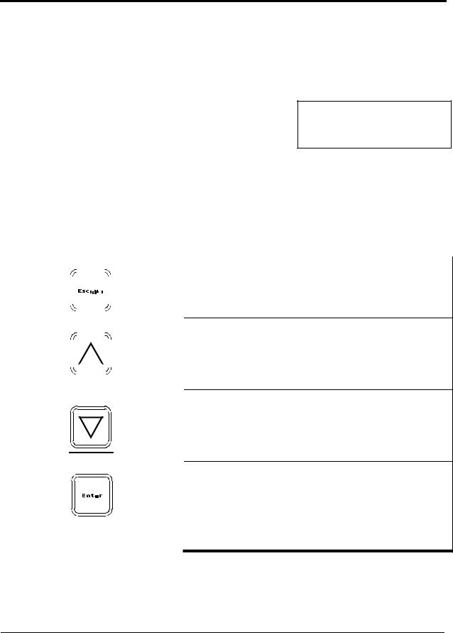
Section 2: Controls and Indicators
Liquid Crystal Display
You can cycle the LCD panel through a menu tree of items that provide both system display information and adjustable parameters. Some display screens allow you to set configuration parameters. The following diagram and tables will help you get familiar with the buttons and LEDs on the ACS Panel and their functionality.
The top level screen for the ACS panel displays battery voltage and current flow, either from the batteries to the inverter (a “–” in front of the current reading) or to the batteries from the charger (a “+” in front of the current reading). The “–” indicates that the inverter/charger is in
inverter mode while the “+” indicates charger mode. In the example shown, the battery voltage is at 12.9 volts and the battery is being charged at the rate of 0.5 amps.
Control Buttons
The ACS LCD display panel includes four menu control keys, an ESCAPE key, an Up arrow key, a Down arrow key, and an ENTER key. The function of each key is described below.
Button Purpose |
Comments |
|
|
|
|
Moves up one level in the menu tree. |
Does not change values. |
|
Moves up one option in the selected menu, or
Selects the next higher value (or previous choice) in a screen that allows the user or installer to scroll through selectable values.
This button is shown as S in the following instructions. For some menus, if you hold the button down, it will scroll rapidly through the numerical values.
Moves down one option in the selected menu, or
Selects the next lower value (or next choice) in a screen that allows the user or installer to scroll through selectable values.
This button is shown as T in the following instructions. For some menus, if you hold the button down, it will scroll rapidly through the numerical values.
Selects the menu level, or is used to enter your choice. If editing of the displayed value is permitted, this key places the value in edit mode, allowing you to scroll through the allowed values, then when pressed again, the current value displayed will be the new value for that menu item.
You can then use the S or T buttons to move through the screens at that level.
If the screen has editable options, you can then use the S or T buttons to move through the options.
Prosine 2.5/3.0 Installation & Operation Guide |
13 |
 Loading...