


 Loading...
About Xantrex
Xantrex Technology Inc. is a world-leading supplier of advanced power electronics and controls with products from 50 watt mobile units to one MW utility-scale systems for wind, solar, batteries, fuel cells, microturbines, and backup power applications in both grid-connected and stand-alone systems. Xantrex products include inverters, battery chargers, programmable power supplies, and variable speed drives that convert, supply, control, clean, and distribute electrical power.
Trademarks
XDL series is a trademark of Xantrex International. Xantrex is a registered trademark of Xantrex International.
Other trademarks, registered trademarks, and product names are the property of their respective owners and are used herein for identification purposes only.
Notice of Copyright
© Xantrex International. All rights reserved.
Disclaimer
UNLESS SPECIFICALLY AGREED TO IN WRITING, XANTREX TECHNOLOGY INC. (“XANTREX”)
(a)MAKES NO WARRANTY AS TO THE ACCURACY, SUFFICIENCY OR SUITABILITY OF ANY TECHNICAL OR OTHER INFORMATION PROVIDED IN ITS MANUALS OR OTHER DOCUMENTATION.
(b)ASSUMES NO RESPONSIBILITY OR LIABILITY FOR LOSS OR DAMAGE, WHETHER DIRECT, INDIRECT, CONSEQUENTIAL OR INCIDENTAL, WHICH MIGHT ARISE OUT OF THE USE OF SUCH INFORMATION. THE USE OF ANY SUCH INFORMATION WILL BE ENTIRELY AT THE USER’S RISK.
Date and Revision
May 2008 - Revision 4
Part Number
975-0107-01-04
Contact Information
Telephone: 1-800-733-5427 (toll free in North America) 1-858-450-0085 (direct)
Fax: 1-858-678-4481
Email: service@programmablepower.com sales@programmablepower.com
Web: www.programmablepower.com
1

|
Table of Contents |
Introduction |
3 |
Specification |
5 |
EMC |
7 |
Safety |
8 |
Installation |
9 |
Connections |
10 |
Initial Operation |
12 |
Manual Operation |
14 |
Remote Operation (XDL 35-5P & XDL 56-4P only) |
21 |
Remote Commands |
30 |
Maintenance |
34 |
Calibration |
34 |
Instructions en Francais |
36 |
Bedienungsanleitung auf Deutsch |
52 |
Istruzioni in Italiano |
68 |
Instrucciones en Español |
84 |
Warranty Information |
99 |
2

Introduction
Unmatched Precision, Unrivalled Performance
The XDL series represents the ‘next generation’ of laboratory power supplies offering an unparalleled level of precision.
Voltage and current are controlled using 16 bit DACs enabling voltages to be set to 1mV resolution even at full output. Indeed, the accuracy is sufficient for the PSU to be used as a calibration source for most hand-held DMMs.
The XDL series uses pure linear technology and offers unrivalled performance in terms of regulation, output noise and dynamics. Line and load regulation are at the limit of measurement (nominally 0·002%). Output noise is less than 500µV rms. Recovery time from transient current pulses is better than 50µs.
The XDL series provides full remote sense capability via dedicated sense terminals. Remote sense is essential to maintain precise regulation at the load (two 0·03Ω connection leads will drop 300mV at 5 Amps). When remote sense is not required, internal local sensing can be selected at the touch of a button.
Multiple Ranges for Greater Flexibility
The XDL series provides multiple ranges for increased current capability at lower voltages. The main range offers 0 to 35 Volts at up to 3 Amps (XDL 35-5) or 0-56V at up to 2 Amps (XDL 56-4). The higher current range provides up to 5 Amps for voltages up to 15V (XDL 35-5) or 4 Amps for voltages up to 25V (XDL 56-4). A further low current range provides enhanced current setting and measurement resolution of 0·1mA.
The product of voltage and current can be displayed at any time by pressing the VxA button. The power is displayed to a resolution of 0·01 Watts.
Fast, Simple and Safe to use
The user interface of the XDL series has been carefully designed to provide rapid control whilst guarding against any possibility of error.
Voltage and current setting can be performed either by direct numeric entry or, for applications where the voltage or current must be gradually changed, by using the quasi-analogue Jog control.
To enable the current limit to be set before connecting the load, the limit setting is displayed when the output is off. Pressing the View Limits key at any time provides a temporary display of the limit values allowing precise adjustment to also be made with the output on.
Setting Memories for Added Convenience
The XDL series provided storage of up to 10 power supply sets-ups in non-volatile memory. Upon mains switch-off, the set-up of the PSU is saved and is automatically restored at switch-on.
OVP and OCP Trips with 'Alarm' Output
The XDL series provides fully adjustable over-voltage and over-current trips which can be used both as a fail-safe against accidental mis-setting and as a protection against inappropriate load conditions. In addition to turning the output off, a trip condition switches the rear panel alarm signal enabling other equipment to be controlled.
For complete protection of the power supply, the trip will also be operated by over-temperature or excess voltage on the sense terminals.
3

Fully Programmable via GPIB, RS232 or USB
The XDL 35-5P and XDL 56-4P incorporate a full bus interface permitting remote control and readback via either GPIB (IEEE-488), RS232 or USB.
The GPIB interface conforms fully with IEEE-488.2 and IEEE-488.1.
The serial interface can be used as a conventional RS232 interface or as part of a multiinstrument addressable RS232 chain.
USB represents the future for medium speed PC connectivity. By adding USB hubs, multiple devices can be connected. A Windows device driver is supplied which creates a virtual COM port, enabling USB to be used with applications that do not directly support it.
XDL series supplies use simple and consistent command structures which make programming particularly easy regardless of which interface is used.
A National Instruments LabWindows* device driver is available.
All power supply settings can be controlled via the bus. Voltage and current can be set to a resolution of 1mV or 0·1mA. Actual voltage and current can be read back together with the power supply status.
* LabWindows is a trademark of National Instruments Corp.
4

Specification
General specifications apply for the temperature range 5°C to 40°C. Accuracy specifications apply for the temperature range 18°C to 28°C after 1 hour warm-up with no load and calibration at 23°C. Typical specifications are determined by design and are not guaranteed.
OUTPUT
Voltage/Current Ranges: |
XDL 35-5 |
|
XDL 56-4 |
|
|
|||
|
0V to 35V/0·001A to 3A |
|
0V to 56V/0·001A to 2A |
|
|
|||
|
0V to 35V/0·1mA to 500mA |
0V to 56V/0·1mA to 500mA |
|
|
||||
|
0V to 15V/0·001A to 5A |
|
0V to 25V/0·001A to 4A |
|
|
|||
Voltage Setting: |
Resolution 1mV |
|
|
|
|
|
||
|
Accuracy ± (0·03% + 5mV) |
|
|
|
|
|
||
Current Setting: |
Resolution 1mA; 0·1mA on 500mA range |
|
|
|
||||
|
Accuracy ± (0·2% + 5mA); ± (0·2% + 0·5mA) on 500mA range. |
|
|
|||||
Output Mode: |
Constant voltage or constant current with automatic cross-over. |
|
|
|||||
|
CI indicator lit in constant current mode. |
|
|
|
||||
Output Switch: |
Electronic, non isolating. Switch illuminated when Output on. |
|
|
|||||
|
Preset voltage and current limit displayed when Output off. |
|
|
|||||
Output Terminals: |
4mm terminals on 19mm (0·75”) spacing for Output; screwless terminals |
|||||||
|
for Sense. Duplicate rear panel Output and Sense screw terminals on |
|||||||
|
remote control model (XDL 35-5P & XDL 56-4P). |
|
|
|
||||
Transient Response: |
<50µs to within 15mV of set level for a change in load current from full |
|||||||
|
load to half load or vice versa. |
|
|
|
|
|||
Voltage Programming |
Maximum time required for output to settle within 1% of its total |
|
|
|||||
Speed: |
excursion (for resistive load). Excludes command processing time. |
|||||||
|
|
|
XDL 35-5 |
|
XDL 56-4 |
|||
|
|
|
Full |
No |
|
Full |
No |
|
|
|
|
Load |
Load |
|
Load |
Load |
|
Up |
15V 5A |
|
6ms |
6ms |
25V/4A |
10ms |
6ms |
|
Up |
35V 3A |
|
20ms |
7ms |
56V/2A |
40ms |
15ms |
|
Up |
35V 500mA |
200ms |
40ms |
56V/500mA |
300ms |
60ms |
||
Down |
15V 5A |
|
6ms |
250ms |
25V/4A |
10ms |
400ms |
|
Down |
35V 3A |
|
25ms |
600ms |
56V/2A |
50ms |
800ms |
|
Down |
35V 500mA |
120ms |
600ms |
56V/500mA |
200ms |
800ms |
||
Ripple and Noise |
Normal mode voltage: <0·35mVrms; <2mVp-p (typ). |
|
|
|
||||
(20MHz bandwidth): |
Normal mode current: <0·2mArms; <20µArms on 500mA range. |
|||||||
Load Regulation: |
For any load change, measured at the output terminals, using |
|
|
|||||
|
remote sense. |
|
|
|
|
|
|
|
|
Voltage <0·01% + 2mV. |
|
|
|
|
|
||
|
Current <0·01% + 250µA; <0.01% +50µA on 500mA range. |
|
|
|||||
|
Add typically 2·5mV for a 0·5V drop in the positive output lead. |
|
|
|||||
|
Specification applies for sense lead resistance <0·5Ω. |
|
|
|||||
Line Regulation: |
Voltage <0·01% + 2mV for 10% line change. |
|
|
|
||||
|
Current <0·01% + 250µA; <0.01%+ 50µA on 500mA range. |
|
|
|||||
Temperature Coefficient: |
Voltage: |
typically <(50ppm + 0·5mV)/°C |
|
|
|
|||
|
Current: |
typically <(100ppm + 1mA)/°C; |
|
|
|
|||
|
|
|
(100ppm + 0·1mA)/°C on 500mA range. |
|
|
|||
Output Protection: |
Output will withstand forward voltages of up to 20V above rated output |
|||||||
|
voltage. Reverse protection by diode clamp for currents up to 3A. |
|||||||
|
|
|
|
|
|
|
|
|
|
|
|
|
|
|
|
5 |
|

Over-voltage Protection: |
Range 1V to 40V (XDL 35-5), 1V to 62V (XDL 56-4) |
(OVP) |
Resolution 0·1V; accuracy ± (2% + 0·5V) |
|
Response time typically 100µs |
Over-current Protection: |
Range 0·01A to 5·5A (XDL 35-5), 0·01A to 4·4A (XDL 56-4) |
(OCP) |
Resolution 0·01A; accuracy ± (0·2% + 0·01A) |
|
Response time typically 35ms |
Protection Functions: |
Output trips off for OVP, OCP, over-temperature and Sense miswiring. |
METER SPECIFICATIONS
Display Type: |
5-digit (Volts), 4-digit (Amps), 14mm (0·56") LED. |
Voltage (CI mode): |
Resolution 10mV |
|
Accuracy ± (0·1% of reading + 10mV) |
Current (CV mode): |
Resolution 0·001A; 0·1mA on 500mA range |
|
Accuracy ± (0·2% + 0·005A); ± (0·2% + 0·5mA) on 500mA range |
V x A: |
Resolution 0·01W; 0·001W on 500mA range |
|
Accuracy ± (0·3% + 0·05W); ± (0·3% + 0·005W) on 500mA range |
ALARM OUTPUT
Isolated rear-panel open-collector output signal. User can select output to be activated for either OVP, OCP, Overtemperature or Sense miswiring, or for any of those four faults.
KEYBOARD & ROTARY CONTROL
All functions, including the selection and set-up of the remote control interfaces, can be set from the keyboard. The rotary jog control can be used to adjust output voltage and current settings in a quasi-analogue mode.
INTERFACES (XDL 35-5P & XDL 56-4P only)
Full remote control facilities are available through the optional RS232, GPIB and USB interfaces. Setting and readback resolutions are the same as for the Output and Meter specifications respectively.
RS232: |
Variable Baud rate, 19200 Baud maximum. 9-pin D-connector. |
|
Single instrument or addressable RS232 chain operation. |
IEEE-488: |
Conforming with IEEE488.1 and IEEE488.2 |
USB: |
Standard USB hardware connection. |
Remote Command |
Typically <80ms between receiving the command terminator for a |
Processing Time: |
step voltage change at the instrument and the output voltage |
|
beginning to change. |
GENERAL
AC Input: |
230V AC or 115V AC ± 10%, 50/60Hz. Installation Category II |
Power Consumption: |
250VA max. |
Operating Range: |
+5ºC to +40ºC, 20% to 80% RH |
Storage Range: |
−40ºC to + 70ºC |
Environmental: |
Indoor use at altitudes up to 2000m, Pollution Degree 2. |
Cooling: |
Intelligent variable-speed fan. |
|
Over-temperature trip shuts down output if internal temperatures |
|
exceed predetermined thresholds. |
Store/Recall: |
Up to 10 set-ups can be saved and recalled via the keyboard or |
|
remote interfaces. |
Safety: |
Complies with EN61010−1 |
EMC: |
Complies with EN61326 |
Size: |
140 x 160 x 290mm (WxHxD), excluding feet and terminals. |
Weight: |
5·5kg |
|
|
6 |
|

EMC
This instrument has been designed to meet the requirements of the EMC Directive 2004/108/EC. Compliance was demonstrated by meeting the test limits of the following standards:
Emissions
EN61326 (1998) EMC product standard for Electrical Equipment for Measurement, Control and Laboratory Use. Test limits used were:
a)Radiated: Class B
b)Conducted: Class B
c)Harmonics: EN61000-3-2 (2000) Class A; the instrument is Class A by product category.
Immunity
EN61326 (1998) EMC product standard for Electrical Equipment for Measurement, Control and Laboratory Use.
Test methods, limits and performance achieved were:
a)EN61000-4-2 (1995) Electrostatic Discharge : 4kV air, 4kV contact, Performance A.
b)EN61000-4-3 (1997) Electromagnetic Field, 3V/m, 80% AM at 1kHz, Performance A.
c)EN61000-4-11 (1994) Voltage Interrupt, 1 cycle, 100%, Performance B.
d)EN61000-4-4 (1995) Fast Transient, 1kV peak (AC line), 0·5kV peak (DC Outputs), Performance B.
e)EN61000-4-5 (1995) Surge, 0·5kV (line to line), 1kV (line to ground), Performance B.
f)EN61000-4-6 (1996) Conducted RF, 3V, 80% AM at 1kHz (AC line only; DC Output connections <3m not tested), Performance A.
According to EN61326 the definitions of performance criteria are:
Performance criterion A: ‘During test normal performance within the specification limits.’
Performance criterion B: ‘During test, temporary degradation, or loss of function or performance which is self-recovering’.
Performance criterion C: ‘During test, temporary degradation, or loss of function or performance which requires operator intervention or system reset occurs.’
Where Performance B is stated it is because DC Output regulation may deviate beyond Specification limits under the test conditions. However, the possible deviations are still small and unlikely to be a problem in practice.
Note that if operation in a high RF field is unavoidable it is good practice to connect the PSU to the target system using screened leads which have been passed (together) through an absorbing ferrite sleeve fitted close to the PSU terminals.
Cautions
To ensure continued compliance with the EMC directive observe the following precautions:
a)after opening the case for any reason ensure that all signal and ground connections are remade correctly and that case screws are correctly refitted and tightened.
b)In the event of part replacement becoming necessary, only use components of an identical type, see the Service Manual.
7

Safety
This power supply is a Safety Class I instrument according to IEC classification and has been designed to meet the requirements of EN61010-1 (Safety Requirements for Electrical Equipment for Measurement, Control and Laboratory Use). It is an Installation Category II instrument intended for operation from a normal single phase supply.
This instrument has been tested in accordance with EN61010-1 and has been supplied in a safe condition. This instruction manual contains some information and warnings which have to be followed by the user to ensure safe operation and to retain the instrument in a safe condition.
This instrument has been designed for indoor use in a Pollution Degree 2 environment in the temperature range 5°C to 40°C, 20% - 80% RH (non-condensing). It may occasionally be subjected to temperatures between +5°C and –10°C without degradation of its safety. Do not operate while condensation is present.
Use of this instrument in a manner not specified by these instructions may impair the safety protection provided. Do not operate the instrument outside its rated supply voltages or environmental range.
WARNING! THIS INSTRUMENT MUST BE EARTHED
Any interruption of the mains earth conductor inside or outside the instrument will make the instrument dangerous. Intentional interruption is prohibited. The protective action must not be negated by the use of an extension cord without a protective conductor.
When the instrument is connected to its supply, terminals may be live and opening the covers or removal of parts (except those to which access can be gained by hand) is likely to expose live parts. The apparatus shall be disconnected from all voltage sources before it is opened for any adjustment, replacement, maintenance or repair.
Capacitors inside the power supply may still be charged even if the power supply has been disconnected from all voltage sources but will be safely discharged about 10 minutes after switching off power.
Any adjustment, maintenance and repair of the opened instrument under voltage shall be avoided as far as possible and, if inevitable, shall be carried out only by a skilled person who is aware of the hazard involved.
If the instrument is clearly defective, has been subject to mechanical damage, excessive moisture or chemical corrosion the safety protection may be impaired and the apparatus should be withdrawn from use and returned for checking and repair.
Make sure that only fuses with the required rated current and of the specified type are used for replacement. The use of makeshift fuses and the short-circuiting of fuse holders is prohibited.
Do not wet the instrument when cleaning it.
The following symbols are used on the instrument and in this manual:-
l
Earth (ground) terminal.
mains supply OFF.
mains supply ON.
alternating current (ac)
direct current (dc)
8
Installation
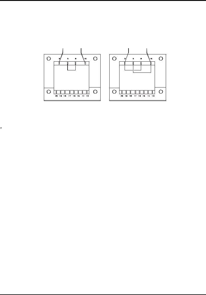
Check that the instrument operating voltage marked on the rear panel is suitable for the local supply. Should it be necessary to change the operating voltage, proceed as follows:
1)Disconnect the instrument from all voltage sources.
2)Remove the screws which retain the top cover and lift off the cover.
3)Change the transformer connections following the appropriate diagram below:
BROWN |
BLUE |
BROWN |
BLUE |
230V |
115V |
4)Refit the cover and the secure with the same screws.
5)To comply with safety standard requirements the operating voltage marked on the rear panel must be changed to clearly show the new voltage setting.
6)Change the fuse to one of the correct rating, see below.
Fuse
The AC fuse is located in the fuse drawer in the lower part of the IEC inlet connector. To change the fuse remove the line cord and open the fuse drawer with a suitable tool.
The correct mains fuse type is 20 x 5mm 250V HBC time-lag with the following rating:
for 230V operation: |
1.6A (T) 250V HBC |
for 115V operation: |
3.15A (T) 250V HBC |
Make sure that only fuses with the required current rating and of the specified type are used for replacement. The use of makeshift fuses and the short-circuiting of fuseholders are prohibited.
Mains Lead
When a three core mains lead with bare ends is provided it should be connected as follows:-
Brown - |
Mains Live |
|
Blue |
- |
Mains Neutral |
Green / Yellow |
- |
Mains Earth |
WARNING! THIS INSTRUMENT MUST BE EARTHED
Any interruption of the mains earth conductor inside or outside the instrument will make the instrument dangerous. Intentional interruption is prohibited. The protective action must not be negated by the use of an extension cord without a protective conductor.
Mounting
This instrument is suitable both for bench use and rack mounting. It is delivered with feet for bench mounting. The front feet include a tilt mechanism for optimal panel angle.
A rack kit for mounting XDL Series power supplies is available from the Manufacturers or their overseas agents. The rack will accommodate 1, 2 or 3 single units or a triple and single unit; a blanking piece is also available for unused positions in the rack.
Ventilation
The power supply is cooled by an intelligent multi-speed fan which vents at the rear. Take care not to restrict the air inlets at the side panels or the exit at the rear. In rack-mounted situations allow adequate space around the instrument and/or use a fan tray for forced cooling.
9

Connections
Front Panel Connections
The load should be connected to the positive (red) and negative (black) terminals marked OUTPUT.
Remote sense connections to the load, if required, are made from the positive (+) and
negative (−) REMOTE SENSE terminals. Remote sense operation is selected from the keyboard or via a remote control interface (XDL 35-5P & XDL 56-4P only); the REMOTE SENSE lamp is lit when remote sense is selected. Switching off remote sense returns the instrument to local sensing at the output terminals.
The terminal marked 


 is connected to the chassis and safety earth ground.
Rear Panel Connections
Output Terminals (XDL 35-5P & XDL 56-4P only)
The output and sense terminals are duplicated on the rear panel screw-terminal block marked Output +, Output −, Sense + and Sense − ; these connections are paralleled with their front panel equivalents.
Remote sense operation is selected from the keyboard or via a remote control interface. When the rear panel terminals are used, remote sense should always be selected to ensure that output regulation is maintained within specification.
RS232 (XDL 35-5P & XDL 56-4P only)
9−pin D−connector compatible with addressable RS232 use. The pin connections are shown below:
Pin |
Name |
Description |
1 |
− |
No internal Connection |
2 |
TXD |
Transmitted data from instrument |
3 |
RXD |
Received data to instrument |
4 |
− |
No internal connection |
5 |
GND |
Signal ground |
6 |
− |
No internal connection |
7 |
RXD2 |
Secondary received data |
8 |
TXD2 |
Secondary transmitted data |
9 |
GND |
Signal ground |
Pin 2, 3 and 5 may be used as a conventional RS232 interface with XON/XOFF handshaking. Pins 7, 8 and 9 are additionally used when the instrument is used in addressable RS232 mode. Signal grounds are connected to instrument ground. The RS232 address is set from the keyboard.
GPIB (XDL 35-5P & XDL 56-4P only)
The GPIB interface is not isolated; the GPIB signal grounds are connected to the instrument ground.
The implemented subsets are:
SH1 AH1 T6 TE0 L4 LE0 SR1 RL1 PP1 DC1 DT1 C0 E2
The GPIB address is set from the keyboard.
10
USB (XDL 35-5P & XDL 56-4P only)
The USB port is connected to instrument ground. It accepts a standard USB cable. The Windows plug-and-play functions should automatically recognise that the instrument has been connected.
Alarm Outputs
The recessed 2-pin connector marked Alarm provides access to an opto-isolated NPN switching transistor, the function of which can be set from the keyboard, see the Alarms section of this manual.
The maximum operating voltage that can be applied across the terminals is 20VDC and the maximum sink current for the switch 'closure' is 1mA.
Do not apply external voltages between the terminals exceeding 30VDC.
11

Initial Operation
This section of the manual is a general introduction to the controls and operation of the instrument and is intended to be read before using the power supply for the first time.
In this manual front panel keys, connections and display indicators are shown in capitals,
e.g. STORE, ESCAPE, OUTPUT, JOG. Messages shown on the 7-segment display are printed in a different type-font, e.g. StorE, GPIb, triP in upper or lower case to represent the characters as they are shown on the 7-segment display.
Switching On, Output On/Off
The power switch is located at the bottom left of the front panel.
At power-up the default behaviour is for the instrument's settings to be restored to those automatically saved when it was switched off, but with the Output always off. However, the user can change this default setting such that the Output is also restored at power-up to its status at power-down, see the Extra Functions section.
The DC output is switched electronically with the ON/OFF key; the key illuminates when the output is on.
Keypad
Only the principles of operation are outlined here; the setting of individual parameters is given in detail in later sections.
The paramount consideration in designing the user interface has been to make changing settings as 'safe' as possible (i.e. with minimal risk of accidentally applying excessive voltages to a target system) whilst achieving ease of use. This has been achieved by requiring the user to confirm (OK) new numeric settings, with the option to ESCAPE at any point or even to simply pause until the operation times-out and the instrument returns to its orginal settings.
In addition a buzzer, illuminated keys, LED indicators and display messages prompt, guide or warn the user such that entry or control errors are minimised. Where some of these features (e.g. beeps or flashing indicators) are considered unnecessary by regular users, the option exists to disable them, see the Extra Functions section.
Under normal conditions the numeric keypad is disabled; pressing any key will cause the buzzer to make a double beep, indicating an illegal operation. To set a voltage or current with the keypad press the V or I NUMERIC SET key; the appropriate display shows 0·000V or 0·000A with the digit to the left of the decimal point flashing. Digits are entered in response to the flashing prompt, together with the decimal point at the appropriate time, and the entry is confirmed with the OK key. If OK is not pressed within 10 seconds of the last numeric key the entry is cancelled and the display returns to its original setting. If ESCAPE is pressed anywhere in the entry procedure, entry is cancelled and the display returns to its original setting.
The OK key is used to confirm most keypad entries. At all other times it becomes the VIEW V/I LIMITS key and pressing it will cause the display to show preset output voltage and current limit for 3 seconds; during this period the LIM indicator in the display flashes.
Pressing SHIFT illuminates the key and gives the numeric keys the functions marked above them (e.g. STORE, RECALL, etc.). When a function is selected by pressing one of these keys SHIFT is cancelled (the SHIFT key is no longer lit). The further key presses required to complete the selected function are described in detail in the sections that follow; if no key is pressed within 10 seconds to complete the function, the function with terminate as if ESCAPE has been pressed. SHIFT is a toggle key; pressing SHIFT again when it has been selected will cancel SHIFT. SHIFT is also cancelled by ESCAPE, or by pressing SET V or SET I.
12

Jog Control
The rotary 'jog' control permits the output voltage or current limit to be incremented or decremented in steps with a resolution set by the JOG SET keys; the output immediately follows the setting, i.e. no OK is required.
At power-up jog is always off. To jog the voltage or current setting press the V or I JOG SET key; the key will illuminate and the JOG indicator under the digit that was last jogged will flash. Whilst the V or I JOG SET key is lit, each further press of the V or I key moves the JOG indicator one digit to the left; the selection 'wraps-round' such that when the largest value of jog increment has been reached the next press returns it to the lowest. The default position at power-up is under the LSD, i.e. the lowest jog increment is selected.
Turning the rotary jog control clockwise/anti-clockwise increments/decrements the selected digit; digits to the left of the one being jogged are automatically incremented/decremented when the decade overflow/underflow point is reached. Digits to the right of the one being jogged remain unchanged unless the jog step overflows/underflows the range maximum/minimum in which case they are set to zero. For example, 33·65V goes to 34·65V goes to 35·00V for the 35V range and a 1V jog increment; 0·160A goes to 0·060A goes to 0·001A for a 0·1A jog decrement.
The jog steps that can be selected are 1mV, 10mV, 100mV and 1mA, 10mA, 100mA; if the 500mA range has been selected the current increment steps are 0·1mA, 1mA, 10mA.
To disable the jog rotary control press the JOG SET OFF key; reselecting JOG SET V or I will enable jog on the last used digit position. Jog is not cancelled by using numeric entry or any of the SHIFT functions but it is disabled whilst that function is enabled.
When in constant voltage mode with the output on the right-hand display will show actual current rather than current limit. If JOG SET I is selected the JOG indicator under the selected digit will flash at half-speed ('lazy' flash). To observe the effect of jogging the current limit it will be necessary to either turn the output off (so that the display permanently shows the current limit) or to press VIEW V/I LIMITS which causes the current limit to be displayed until 3 seconds after movement of the jog control ceases. The 'lazy' flash is also used when JOG SET V has been selected and actual voltage is being shown because the supply has gone into current limit.
The factory default is to flash the JOG indicator under the selected digit for the whole time that jog is selected so that the user is constantly reminded which parameter can be incremented/ decremented. Where this degree of reminding is considered inadequate the user can select, using the Extra Functions capability, to flash the digit itself; conversely, where the flashing is considered intrusive the user can select to not flash the JOG indicator (except when the 'lazy' flash is shown).
Display
The display shows the voltage on the left (5 digits) and the current on the right (4 digits). These 7- segment displays are also used to show prompts during the some of the function settings (e.g. memory store/recall or remote control address setting) using the limited 'character set' that can be achieved with a 7-segment display; these are necessarily a mixture of upper and lower case letters.
Above and below the 7-segment display are several secret-until-lit annunciators. To the right, above the current display, are the indicators which show the selected operating range: 35V/3A, 15V/5A or 35V/500mA (XDL 35-5); 56V/2A, 25V/4A, 56V/500mA (XDL 56-4); the
indicators light beneath the range printed immediately above them and, in the case of the 500mA range, the indicator is marked mA to emphasise that the current display is now showing mA. The other annunciators above the displays are:
CI, indicating that the instrument is in constant current mode; LIM, which flashes when the VIEW V/I LIMITS key is pressed to show the set voltage/set current limit in the display; REM, which lights when the instrument is under control from a remote interface (XDL 35-5P & XDL 56-4P only).
Below the three least significant digits of both the voltage and current displays are the JOG indicators; the appropriate indicator flashes when the jog function is being used, see the Jog Control section above.
13

Manual Operation
New users should first read the Initial Operation chapter which describes the operating principles of the keypad and rotary jog control.
Set Voltage
The left-hand display shows the set voltage to a resolution of 1mV, except when the instrument is in constant current (CI) mode. In CI mode the actual output voltage (which will be less than the set voltage) is shown and the display resolution is 10mV; the least significant digit (1mV resolution) is always displayed as a zero.
The voltage can be set directly from the numeric keypad: press the NUMERIC SET V key, enter the new value using the numeric keys and confirm by pressing OK. The broad principles of keypad entry are explained in the Initial Operation chapter, which should be read by new users.
When SET V is pressed the display shows 0·000; a new voltage is then entered (e.g. 12·345V is entered as 1, 2, ·, 3, 4, 5) and confirmed by OK. The position of the decimal point in the display is fixed to reduce the risk of entering a wrong value. As a consequence, and to avoid the need to enter leading zeroes (e.g. 2·345V is entered as 2, ·, 3, 4, 5, OK), numbers to the left of the decimal point are shown slightly differently to the numbers to the right of the decimal point during number entry; this is self-evident during number entry.
The minimum voltage setting is 0·000V; the maximum setting is 35·000V (15·000V on the 15V/5A range).
Pressing OK at any point will set the voltage entered with any remaining digits set to zero, e.g. 1, 2, ·, 3, OK will set 12·300V; 1, OK will set 1·000V; pressing OK immediately after SET V (while the display shows 0·000V) will set 0·000V.
Pressing ESCAPE at any time during the sequence, or making no further key press within 10 seconds of the previous one will cause the display to return to its original reading before SET V was pressed.
Entering a voltage outside the range maximum (including trying to enter 3 digits before the decimal point) or trying to enter more than 5 digits will cause the buzzer to beep twice; the last key entry will be ignored.
The voltage can also be set using the Jog control. Pressing JOG SET V will illuminate the V key and the JOG indicator under the digit that was last jogged will flash. Whilst the V key is lit, each further press will move the JOG indicator one digit to the left; the selection 'wraps round' such that when the largest value of jog increment has been reached the next press returns it to the lowest. The default position at power-up is under the LSD, i.e. the lowest jog increment is selected. The jog steps that can be selected are 1mV, 10mV and 100mV.
With jog enabled the output voltage can be incremented or decremented with the rotary jog control with a step resolution indicated by the position of the flashing JOG indicator. The output immediately follows the setting, i.e. no OK is required. If the output goes into constant current mode (indicated by the CI indicator flashing) the left-hand display shows actual voltage not set voltage. If JOG SET V is selected the JOG indicator under the selected digit will flash at half speed ('lazy' flash). To observe the effect of jogging the set voltage it will be necessary to either turn the output off (so that the display permanently shows the set voltage) or to press
VIEW V/I LIMITS which causes the set voltage to be displayed until 3 seconds after movement of the jog control ceases.
Note that in constant current mode the actual voltage is measured and displayed to only 10mV resolution; the 1mV digit permanently displays zero.
Further details on the jog control can be found in the Initial Operation chapter.
14

Set Current Limit
With the output off, the right-hand display shows the current limit to a resolution of 1mA (0·1mA on the 500mA range).
The current limit can be set directly from the numeric keypad: press the NUMERIC SET I key, enter the new value using the numeric keys and confirm by pressing OK. The broad principles of keypad entry are explained in the Initial Operation chapter, which should be read by new users.
When SET I is pressed the display shows 0·000; a new current is then entered (e.g. 1·234A is entered as 1, · , 2, 3, 4,) and confirmed by OK. The position of the decimal point in the display is fixed to reduce the risk of entering a wrong value. As a consequence, and to avoid the need to enter or display leading zeroes (e.g. 0·234A is entered as ·, 2, 3, 4, OK), numbers to the left of the decimal point are shown slightly differently to the numbers to the right of the decimal point during number entry; this is self-evident during number entry.
The minimum current setting is 0·001A (0·1mA on the 500mA range); the maximum setting is 3·000A, 5·000A or 500·0mA (XDL 35-5), 2·000A, 4.000A or 500·0mA (XDL 56-4) according to range, i.e. there is no over-range capability.
Pressing OK at any point will set the current entered with any remaining digits set to zero,
e.g. 1, ·, 2, OK will set 1·200A; 1, OK will set 1·000A; pressing OK immediately after SET V (while the display shows 0·000A) will set 0·001A.
Pressing ESCAPE at any time during the sequence, or making no key press within 10 seconds of the previous one will cause the display to return to its original reading before SET I was pressed.
Entering a value outside the range maximum (including trying to enter 2 digits before the decimal point) or trying to enter more than 4 digits will cause the buzzer to beep twice; the last key entry will be ignored.
The current limit can also be set using the rotary jog control. Pressing JOG SET I will illuminate the key and the JOG indicator under the digit that was last jogged will flash. Whilst the I key is lit, each further press will move the JOG indicator one digit to the left; the selection 'wraps round' such that when the largest value of jog increment has been reached the next press returns it to the lowest. The default position at power-up is under the LSD, i.e. the lowest jog increment is selected. The jog steps that can be selected are 1mA, 10mA and 100mA (0·1mA, 1mA and 10mA on the 500mA range).
With jog enabled the current limit can be incremented or decremented with the rotary jog control with a step resolution indicated by the position of the flashing JOG indicator. The output immediately follows the setting, i.e. no OK is required. With the output on the right-hand display shows actual current, not current limit (except in constant current mode). If JOG SET I is selected the JOG indicator under the selected digit will flash at half speed ('lazy' flash). To observe the effect of jogging the current limit it will be necessary to either turn the output off (so that the display permanently shows the current limit) or to press VIEW V/I LIMITS which causes the current limit to be displayed until 3 seconds after movement of the jog control ceases.
Instantaneous Current Output
The current limit control can be set to limit the continuous output current to levels down to 1mA (0·1 mA on 500mA range). However, in common with all precision bench power supplies, a capacitor is connected across the output to maintain stability and good transient response. This capacitor charges to the output voltage and short-circuiting of the output will produce a current pulse as the capacitor discharges which is independent of the current limit setting.
15

Range Selection
The instrument has three ranges: 35V/3A, 15V/5A and 35V/500mA (XDL 35-5); 56V/2A, 25V/4A and 56V/500mA (XDL 56-4). The selected range is shown by an illuminated indicator below the appropriate legend at the top right-hand side of the instrument; when the 500mA range is selected the indicator legend is mA to emphasise that the current meter now shows milliamps not amps.
To change range press SHIFT followed by RANGE or RANGE ; each press of RANGE selects the next range to the left; each press of RANGE selects the next range to the right; there is no 'wrap-round'. When the range is changed the indicator that represents the new range and the OK key both flash; pressing OK sets the new range. To exit without changing range press ESCAPE. Pressing any other key whilst in range change mode causes the warning buzzer to beep twice; no other action is taken. If OK is not pressed within 10 seconds of the last range change key press the range selection remains unchanged.
The range can only be changed when the output is off. Pressing the RANGE or RANGE keys with the output on will cause the output ON/OFF key (as well as the OK key) to flash. The output may be turned off with the ON/OFF key and the range then changed by pressing OK, or OK may be pressed directly in which case the output is automatically turned off and the range then changed.
If a range change causes a voltage or current limit setting to exceed the corresponding maximum of the new range the range change is accepted but the setting is made equal to the maximum of the new range.
Note that the OVP setting is not changed when the range is changed (e.g. an OVP setting of 38V remains valid on the 15V range); it is left to the user to independently change the OVP setting if required.
Connection to the Load
The load should be connected to the positive (red) and negative(black) OUTPUT terminals. Both are fully floating and either can be connected to ground.
Remote Sensing
The instrument has a very low output impedance, but this is inevitably increased by the resistance of the connecting leads. At high currents this can result in significant differences between the indicated source voltage and the actual load voltage (two 20mΩ connecting leads will drop 0·2V at 5 Amps, for instance). This problem can be minimised by using short, thick, connecting leads, but where necessary it can be completely overcome by using the remote sense capability.
This requires the sense terminals to be connected to the output at the load instead of at the source; insert wires into the spring-loaded REMOTE SENSE terminals and connect directly to the load.
Select remote sense by pressing SHIFT, SENSE; the OK key flashes and the lamp above the remote sense terminals lights to show that remote sense will be selected when OK is pressed. Press OK to confirm; press ESCAPE to exit without changing state. Remote sense is turned off by pressing SHIFT, SENSE again; the OK key flashes and the remote sense lamp goes off to indicate that local sense will be restored when OK is pressed. Press OK to confirm; press ESCAPE to exit without changing state.
To avoid instability and transient response problems, care must be taken to ensure good coupling between each output and sense lead. This can be done either by twisting the leads together or by using coaxially screened cable (sense through the inner). An electrolytic capacitor directly across the load connection point may also be beneficial.
The voltage drop in each output lead must not exceed 0·5 Volts.
The XDL 35-5P/ XDL 56-4P has rear panel output and sense terminals, appropriate for when the instrument is used in a rack. The rear panel sense terminals should always be used with the rear panel output connections.
16

Sense Miswiring Trip
The output will be tripped off if the voltage between an output terminal and its corresponding sense terminal exceeds approximately 1V; this will happen if the sense wires are wired at the load to the wrong output or if an attempt is made to draw power from the sense wires.
If the sense terminals are miswired in this way the display shows the message SENSE triP and the output is turned off. Pressing ESCAPE at this point removes the message and the display now shows the preset voltage and current limit. When the cause of the trip has been corrected the output can be turned on again.
Series or Parallel Connection with Other Outputs
The outputs of the power supply are fully floating and may be used in series with other power supply units to generate high DC voltages up to 300V DC.
The maximum permissible voltage between any terminal and earth ground (

 ) is 300VDC.
WARNING! Such voltages are exceedingly hazardous and great care should be taken to shield the output terminals for such use. On no account should the output terminals be touched when the unit is switched on under such use. All connections to the terminals must be made with the power switched off on all units.
It should be noted that the unit can only source current and cannot sink it, thus units cannot be series connected in anti-phase.
The unit can be connected in parallel with others to produce higher currents. Where several units are connected in parallel, the output voltage will be equal to that of the unit with the highest output voltage setting until the current drawn exceeds its current limit setting, upon which the output will fall to that of the next highest setting, and so on. In constant current mode, units can be connected in parallel to provide a current equal to the sum of the current limit settings.
Note that the output terminals are rated at 15A maximum; if several outputs are operated in parallel to source higher currents than this the junction should be made at a separate point, not one of the terminals.
Over-Voltage Protection
Over-Voltage Protection (OVP) can be set from 1·0V to 40V (XDL 35-5), 1·0V to 62V (XDL 56-4). If the output voltage exceeds the set OVP the output is immediately shut down (typically within 100µs), thus avoiding damage to the circuit under test. The OVP circuit will protect against accidental excessive voltage settings from the front panel or via the remote control interfaces, external voltages impressed across the output terminals, or a failure in the control circuitry of the instrument itself.
To set OVP press SHIFT, OVP; the 100mV step JOG indicator will start flashing and the jog rotary control can be used to increment/decrement the OVP setting in 100mV steps. Press OK to confirm the new setting; to exit without entering a new value press ESCAPE. The factory default setting is 40·0V (XDL 35-5), 62·0V (XDL 56-4).
If the OVP is tripped the display shows the message OUP triP and the output is turned off. Pressing ESCAPE at this point removes the message and the display now shows the preset voltage and current limit. When the cause of the OVP has been removed (or the OVP limit changed) the output can be turned on again.
Note that the OVP setting is not changed when the range is changed (e.g. an OVP setting of 38V remains valid on the 15V range); it is left to the user to independently change the OVP setting if required.
Note also that it is possible and valid to set OVP below the set voltage. If the supply is in constant current mode the output voltage will be below the set voltage; OVP could be set such that is was above the actual output voltage but below the set voltage. This could be used to trip the output under a fault condition which caused the load impedance to increase and the actual output voltage to therefore rise above the OVP point.
17

Over-Current Protection
Over-Current Protection (OCP) can be set from 0·01A to 5·5A (XDL 35-5), 0·01A to 4·4A
(XDL 56-4). If the output current exceeds the set OCP the output is shut down (typically within 35ms).
To set OCP press SHIFT, OCP; the 10mA step JOG indicator will start flashing and the jog rotary control can be used to increment/decrement the OCP setting in 10mA steps. Press OK to confirm the new setting; to exit without entering a new value press ESCAPE. The factory default setting is 5·50A.
If the OCP is tripped the display shows the message OCP triP and the output is turned off. Pressing ESCAPE at this point removes the message and the display now shows the preset voltage and current limit. When the cause of the OCP has been removed (or the OCP limit changed) the output can be turned on again.
Note that as with OVP, the OCP setting is not changed when the range is changed.
Note also that is possible and valid to set OCP below the set current limit. For example, the power supply may be used to repetitively test a unit under test (UUT) which normally takes a peak current of, say, 2 Amps. However, a faulty UUT would take a current of more than 2 Amps and would be damaged by being left in a 2 Amp current-limited state. In this case the current limit could be set to 2·1A, say, and the OCP set to 2·0A to ensure that a faulty UUT will trip the supply off.
Output Protection
In addition to OVP and OCP for forward over-voltage and over-current protection, the output is protected from reverse voltages by a diode; the continuous reverse current must not exceed 3 Amps although transients can be much higher.
Output Power (V x A)
If SHIFT, V x A is pressed the voltage display shows the product of measured output voltage x measured current and the current display shows UA. V x A is a momentary function, i.e. it gives an instantaneous, not a continuous, reading of the output power; the reading is held whilst the key is pressed. Pressing V x A cancels SHIFT. Jog is temporarily disabled (and the JOG indicators are turned off) during the V x A display.
Temperature Trip
If the safe internal temperature limit is exceeded because, for example, the fan vents have been blocked, the output is turned off and the display will show OTP triP. Pressing ESCAPE at this point will do one of two things:
i.If the over-temperature condition has already cleared the message will be removed and the display will show preset voltage and current limit. Assuming the cause of the over-temperature has been rectified the output can be turned on again.
ii.If the instrument is still above the safe temperature limit the OTP triP message will flash slowly ('lazy' flash) until the instrument has cooled, at which point the display will show preset voltage and current limit again. Assuming the cause of the over-temperature has been rectified the output can be turned on again.
Alarm Output
The recessed 2-pin connector on the rear panel is directly connected to an opto-coupled NPN switching transistor (pin 1 emitter, pin 2 collector) which is turned on (i.e. switch 'closure') according to the conditions specified in the Extra Functions section, see later. The default condition is switch closure for any trip condition (OVP, OCP, SENSE or OTP). The maximum open-circuit voltage permitted across the switch is 30VDC and the nominal sink current for switch closure is 1mA.
18

Store Settings
The instrument can store 10 set-ups in non-volatile memory; the parameters stored are range, voltage, current limit, OVP and OCP. The output state and remote sense setting are not stored.
To store a set-up press SHIFT, STORE, store no., OK; the store no. is any key 0 to 9.
After key-presses SHIFT, STORE, the display shows StorE - ; the SHIFT function is cancelled (the light goes off). At this point, pressing any number key will display that number in
place of the – and show either E |
(store Empty) or F (store Full) beside it, |
e.g. StorE 1.E, StorE 2.F . |
Any number of stores can be checked by pressing one |
number after another (i.e. without having to press SHIFT, STORE each time) before the selection is confirmed with the OK key. A full store can be overwritten with new settings. At any time before the OK key is pressed the store function can be exited without saving a set-up by pressing ESCAPE or by waiting 10 seconds from the last key entry.
Deleting Stored Settings
Any store can be returned to 'empty' as follows: select the store by pressing SHIFT, STORE, store no.; at that point press · . The display now shows dELEt in place of StorE , e.g.
; pressing OK deletes the content of the store.
Recall Settings
To recall a set-up press SHIFT, RECALL, store no., OK; the store no. is any key 0 to 9. After key-presses SHIFT, RECALL, the display shows rECAL – ; the SHIFT function is cancelled (the light goes off). At this point, pressing any key 0 to 9 will preview the voltage and current settings of that store number; the settings flash to indicate preview mode.
Any number of stores can be previewed by pressing one number after another (i.e. without having to press SHIFT, RECALL each time) before the selection is confirmed with the OK key. Empty stores are indicated by flashing – in every digit position. At any time before the OK key is pressed the Recall function can be exited without recalling a set-up by pressing ESCAPE or by waiting 10 seconds from the last key entry.
Settings may be recalled with the output on or off. However, if the recalled setting involves a range change the output is turned off to avoid any 'glitches'. After pressing SHIFT, RECALL, store no., the ON/OFF key will flash (as well as the OK key) if completing the recall involves a range change. The output may be turned off with the ON/OFF key and the recall then completed by pressing OK, or OK may be pressed directly in which case the output is automatically turned off and the recall completed.
Extra Functions
Variations on some of the factory default functions can be set by the user by using the # extra functions facility. Each function change, detailed in the list below is accessed by pressing SHIFT, #, nn, when nn is the 2-digit number in the list below; the SHIFT light goes off and the buzzer gives a confirmation beep when the 2-digit number entry is complete.
# Code Function
00 Output always off at power-up (factory default)
01 Output status at power-up the same as at last power-down
20Alarm output 'open' for Output off, 'closed' for Output on
21(not used in single output PSU)
22Alarm output 'closed' when over-temperature trip occurs
23Alarm output 'closed' when sense trip occurs
24Alarm output 'closed' when over-current trip occurs
19

25Alarm output 'closed' when over-voltage trip occurs
26Alarm output 'closed' when any trip occurs (factory default)
30Buzzer off
31Buzzer on (factory default). A single beep indicates confirmation, a double beep indicates a wrong entry.
40Jog digit flashes, JOG indicator only flashes when jog is 'hidden'
41JOG indicator always flashes, except when 'hidden' (factory default)
42JOG indicator doesn't flash, except when 'hidden' (lazy flash)
91Loads default calibration parameters. Refer to Service Manual.
92Shows firmware version number in the display
93Sets these # settings to their factory default
99 Enter calibration mode. Refer to Service Manual.
Factory Default Settings
The ex-factory default settings (which will apply at first power-up) are as follows:
Range: |
35V/3A (XDL 35-5); 56V/2A (XDL 56-4) |
|
Voltage: |
1·000V |
|
Current Limit: |
1·000A |
|
OVP: |
40V (XDL 35-5); 62V (XDL 56-4) |
|
OCP: |
5·5A (XDL 35-5); 4·4A (XDL 56-4) |
|
Output: |
Output off; local Sense |
|
# Settings: |
00 |
Output always off at power-up |
|
26 |
Alarm output 'closed' when any trip condition occurs |
|
31 |
Buzzer on |
|
41 |
JOG indicator always flashes; 'lazy' flash when hidden |
RS232: |
9,600 Baud (XDL 35-5P & XDL 56-4P only) |
|
Address: |
11 (XDL 35-5P & XDL 56-4P only) |
|
Error Messages
The following hardware errors are indicated by showing the appropriate error number in the display. The OK key will flash and if pressed the error will be ignored and operation will continue as described.
Error No. |
Error Description |
Action on pressing OK |
1 |
Calibration constants corrupted at power-up |
Loads default calibration parameters |
2 |
# functions corrupted at power-up |
Loads default # settings |
3 |
Power-down settings not correctly loaded at |
Loads factory default power-up settings |
|
power up |
|
Switching the instrument off with the error message showing will leave all settings unchanged.
20
Remote Operation (XDL 35-5P & XDL 56-4P
only)
The instrument can be remotely controlled via its RS232, USB or GPIB interfaces. When using RS232 it can either be the only instrument connected to the controller or it can be part of an addressable RS232 chain which permits up to 32 instruments to be addressed from one RS232 port.
The USB interface operates internally through the instrument's RS232 interface. USB remote control consequently operates exactly as described for single-instrument RS232 use but via the USB connector. The instrument operates at the maximum Baud rate (19200) in USB mode. The virtual COM port on the controlling computer, which is set up using the driver software supplied, must be set to the same Baud rate. Application software on the computer can then access the instrument as if it is connected via the RS232 connector. The USB port cannot, however, be used as part of an addressable RS232 chain.
Some of the following sections are general and apply to all modes (single instrument RS232, USB, addressable RS232 chain and GPIB); others are clearly only relevant to a particular interface or mode. It is only necessary to read the general sections plus those specific to the intended remote control mode.
Remote command format and the remote commands themselves are detailed in the Remote Commands chapter.
Control Bus, Instrument Address and Baud Rate Selection
For successful operation each instrument connected to a GPIB bus or addressable RS232 chain must be assigned a unique address. For addressable RS232 all instruments in the chain must be set to the same Baud rate.
Press SHIFT, Bus Type to display the currently selected bus type. To change to another bus type scroll through the available types using the rotary control until the required type is displayed. Press OK to select the displayed type or ESCAPE to retain the previous selection.
Press SHIFT, Addr/Baud to display the currently selected instrument bus address. If the currently selected bus type is RS232 then pressing Addr/Baud again displays the currently selected Baud rate and repeated presses alternate between the two. To change the address scroll through the available addresses using the rotary control when the address is displayed. The address can be set between 1 and 31 inclusive and the same address is used for both GPIB and addressable RS232; the address setting is ignored in USB mode. To change the Baud rate scroll through the available rates using the rotary control when the Baud rate is displayed. Press OK to select the last displayed address and Baud rate or ESCAPE to retain the previous selections. Note that RS232 must be selected before the Baud rate can be selected; the Baud rate is fixed at maximum (19200) for USB.
Remote/Local Operation
At power-on the instrument will be in the local state with the REM indicator off. In this state all keyboard operations are possible. When the instrument is addressed to listen and a command is received the remote state will be entered and REM will be turned on. In this state the keyboard is locked out and remote commands only will be processed. The instrument may be returned to the local state by pressing the LOCAL key; however, the effect of this action will only remain until the instrument is addressed again or receives another character from the interface, when the remote state will once again be entered.
21
RS232 Interface
RS232 Interface Connector
The 9-way D-type serial interface connector is located on the instrument rear panel. The pin connections are as shown below:
Pin |
Name |
Description |
1 |
- |
No internal connection |
2 |
TXD |
Transmitted data from instrument |
3 |
RXD |
Received data to instrument |
4 |
- |
No internal connection |
5 |
GND |
Signal ground |
6 |
- |
No internal connection |
7 |
RXD2 |
Secondary received data (addressable RS232 only) |
8 |
TXD2 |
Secondary transmitted data (addressable RS232 only) |
9 |
GND |
Signal ground (addressable RS232 only) |
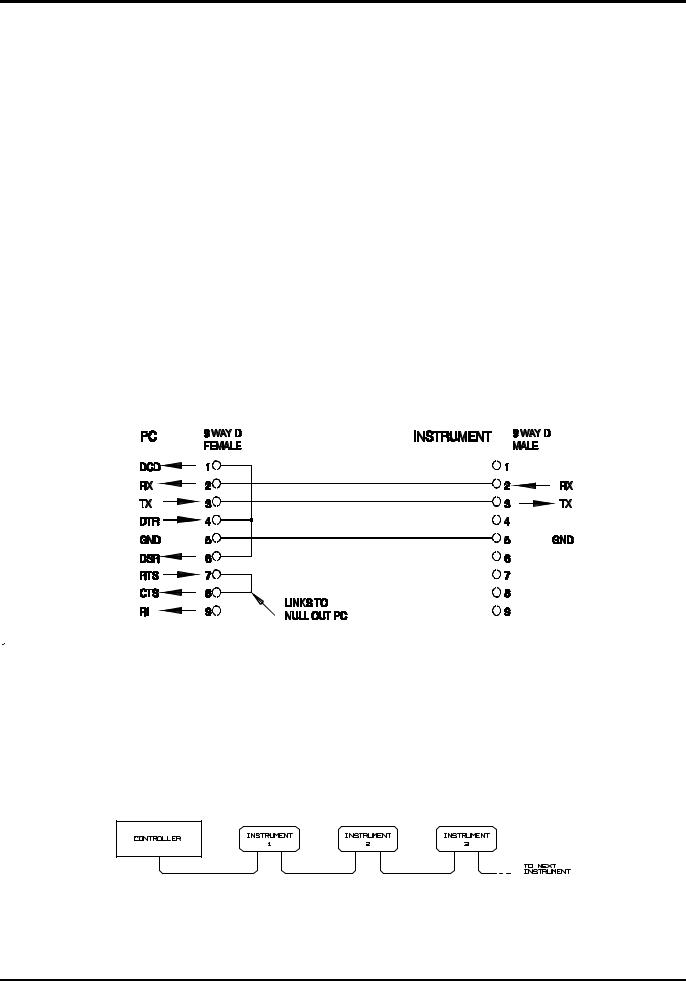
Single Instrument RS232 Connections
For single instrument remote control only pins 2, 3 and 5 are connected to the PC. However, for correct operation links must be made in the connector at the PC end between pins 1, 4 and 6 and between pins 7 and 8, see diagram. Pins 7 and 8 of the instrument must not be connected to the PC, i.e. do not use a fully wired 9–way cable.
Baud Rate is set as described above in Address and Baud Rate Selection; the other parameters are fixed as follows:
Start Bits: |
1 |
Parity: None |
Data Bits: |
8 |
Stop Bits: 1 |
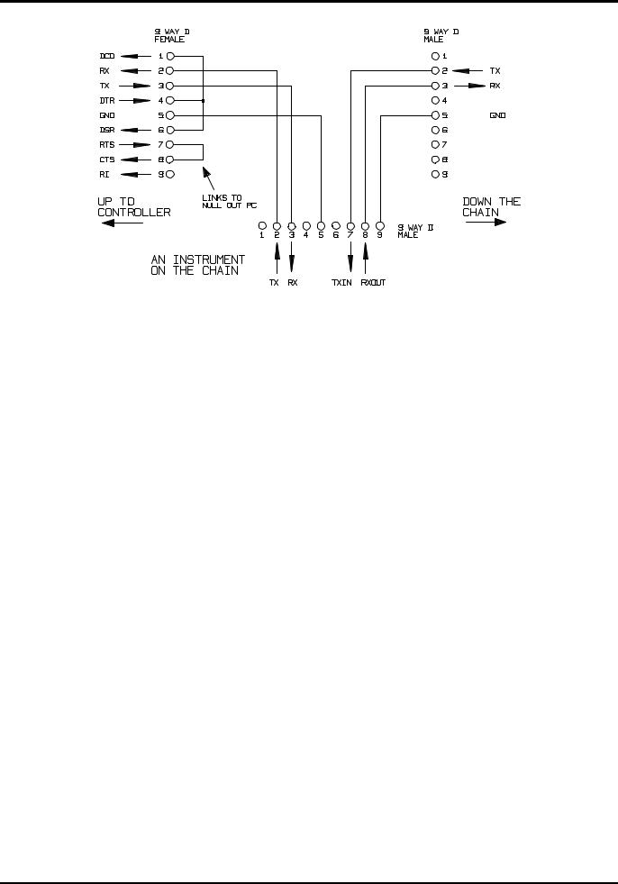
Addressable RS232 Connections
For addressable RS232 operation pins 7, 8 and 9 of the instrument connector are also used. Using a simple cable assembly, a 'daisy chain' connection system between any number of instruments, up to the maximum of 32 can be made, as shown below:
The daisy chain consists of the transmit data (TXD), receive date (RXD) and signal ground lines only. There are no control/handshake lines. This makes XON/XOFF protocol essential and allows the inter-connection between instruments to contain just 3 wires. The wiring of the adaptor cable is shown below:
22
All instruments on the interface must be set to the same baud rate and all must be powered on, otherwise instruments further down the daisy chain will not receive any data or commands.
The other parameters are fixed as follows:
Start Bits: |
1 |
Parity: None |
Data Bits: |
8 |
Stop Bits: 1 |
RS232 Character Set
Because of the need for XON/XOFF handshake it is possible to send ASCII coded data only; binary blocks are not allowed. Bit 7 of ASCII codes is ignored, i.e. assumed to be low. No distinction is made between upper and lower case characters in command mnemonics and they may be freely mixed. The ASCII codes below 20H (space) are reserved for addressable RS232 interface control. In this manual 20H, etc. means 20 in hexadecimal
Addressable RS232 Interface Control Codes
All instruments intended for use on the addressable RS232 bus use the following set of interface control codes. Codes between 00H and 1FH which are not listed here as having a particular meaning are reserved for future use and will be ignored. Mixing interface control codes inside instrument commands is not allowed except as stated below for CR and LF codes and XON and XOFF codes.
When an instrument is first powered on it will automatically enter the NonAddressable mode. In this mode the instrument is not addressable and will not respond to any address commands. This allows the instrument to function as a normal RS232 controllable device. This mode may be locked by sending the Lock Non-Addressable mode control code, 04H. The controller and instrument can now freely use all 8 bit codes and binary blocks but all interface control codes are ignored. To return to addressable mode the instrument must be powered off.
To enable addressable mode after an instrument has been powered on the Set Addressable Mode control code, 02H, must be sent. This will then enable all instruments connected to the addressable RS232 bus to respond to all interface control codes. To return to Non-Addressable mode the Lock Non-Addressable mode control code must be sent which will disable addressable mode until the instruments are powered off.
Before an instrument is sent a command it must be addressed to listen by sending the Listen Address control code, 12H, followed by a single character which has the lower 5 bits corresponding to the unique address of the required instrument, e.g. the codes A-Z or a-z give the addresses 1-26 inclusive while @ is address 0 and so on. Once addressed to listen the instrument will read and act upon any commands sent until the listen mode is cancelled.
23

Because of the asynchronous nature of the interface it is necessary for the controller to be informed that an instrument has accepted the listen address sequence and is ready to receive commands. The controller will therefore wait for Acknowledge code, 06H, before sending any commands, The addressed instrument will provide this Acknowledge. The controller should timeout and try again if no Acknowledge is received within 5 seconds.
Listen mode will be cancelled by any of the following interface control codes being received:
12H Listen Address followed by an address not belonging to this instrument. 14H Talk Address for any instrument.
03H Universal Unaddress control code.
04H Lock Non-Addressable mode control code.
18H Universal Device Clear.
Before a response can be read from an instrument it must be addressed to talk by sending the Talk Address control code, 14H, followed by a single character which has the lower 5 bits corresponding to the unique address of the required instrument, as for the listen address control code above. Once addressed to talk the instrument will send the response message it has available, if any, and then exit the talk addressed state. Only one response message will be sent each time the instrument is addressed to talk.
Talk mode will be cancelled by any of the following interface control codes being received: 12H Listen Address for any instrument.
14H Talk Address followed by an address not belonging to this instrument. 03H Universal Unaddress control code.
04H Lock Non-Addressable mode control code.
18H Universal Device Clear.
Talk mode will also be cancelled when the instrument has completed sending a response message or has nothing to say.
The interface code 0AH (LF) is the universal command and response terminator; it must be the last code sent in all commands and will be the last code sent in all responses.
The interface code 0DH (CR) may be used as required to aid the formatting of commands; it will be ignored by all instruments. Most instruments will terminate responses with CR followed by LF.
The interface code 13H (XOFF) may be sent at any time by a listener (instrument or controller) to suspend the output of a talker. The listener must send 11H (XON) before the talker will resume sending. This is the only form of handshake control supported by addressable RS232 mode.
Full List of Addressable RS232 Interface Control Codes
02H |
Set Addressable Mode. |
03H |
Universal Unaddress control code. |
04H |
Lock Non-Addressable mode control code. |
06H |
Acknowledge that listen address received. |
0AH |
Line Feed (LF); used as the universal command and response terminator. |
0DH |
Carriage Return (CR); formatting code, otherwise ignored. |
11H |
Restart transmission (XON). |
12H |
Listen Address - must be followed by an address belonging to the required instrument. |
13H |
Stop transmission (XOFF). |
14H |
Talk Address - must be followed by an address belonging to the required instrument. |
18H |
Universal Device Clear. |
24

USB Interface
The USB interface allows the instrument to be controlled using RS232 protocol via a computer’s USB port. This is useful where the computer’s standard RS232 COM ports are fully utilised or non-existent.
The instrument is supplied with a disk containing drivers for various versions of Windows, including Win98 and 2000. The disk also contains a text file with information and details of the software installation procedure.
Installation of the interface driver is achieved by connecting the instrument to a PC via a standard USB cable. The Windows’ plug and play functions should automatically recognise the addition of new hardware attached to the USB interface and if this is the first time the connection has been made, prompt for the location of a suitable driver. Provided that the standard Windows prompts are followed correctly Windows will install the appropriate driver and establish a virtual COM port within the PC. The number of the new COM port will depend upon the number of co-existing COM ports within the PC. The virtual COM port can be driven by Windows applications in exactly the same way as a standard port.
Note that it is necessary to set the virtual COM port to the same Baud rate as the instrument being controlled in exactly the same way as with a standard RS232 connection.
The driver will remain installed on the PC so that the establishment of a virtual COM port is done automatically each time the instrument is connected to the PC via USB in the future.
Further virtual COM ports are created for each additional instrument connected to the PC via USB. Each instrument is assigned a separate virtual COM port when it is first connected and the same COM port will be assigned each time that instrument is subsequently connected; the PC software makes use of the unique code embedded in each instrument to link it to the same virtual COM port irrespective of which physical USB port it is connected to.
Use can also be made of the ADDRESS? command to easily identify which instrument is being controlled by a particular COM port. Although the addressing capability is ignored in USB operation the address can still be set and used as an identifier; set each USB-connected instrument to a different address and send the ADDRESS? command from each virtual COM port to confirm which instrument is connected to that port.
The supplied disk contains an uninstall program should this be required.
GPIB Interface
The GPIB interface 24-way connector is located on the instrument rear panel. The pin connections are as specified in IEEE Std. 488.1-1987 and the instrument complies with IEEE Std. 488.1-1987 and IEEE Std. 488.2-1987.
GPIB Subsets
This instrument contains the following IEEE 488.1 subsets:
Source Handshake |
SH1 |
Acceptor Handshake |
AH1 |
Talker |
T6 |
Listener |
L4 |
Service Request |
SR1 |
Remote Local |
RL1 |
Parallel Poll |
PP1 |
Device Clear |
DC1 |
Device Trigger |
DT0 |
Controller |
C0 |
Electrical Interface |
E2 |
25

GPIB IEEE Std. 488.2 Error Handling – Query Error Register
The IEEE 488.2 UNTERMINATED error (addressed to talk with nothing to say) is handled as follows. If the instrument is addressed to talk and the response formatter is inactive and the input queue is empty then the UNTERMINATED error is generated. This will cause the Query Error bit to be set in the Standard Event Status Register, a value of 3 to be placed in the Query Error Register and the parser to be reset. See the Status Reporting section for further information.
The IEEE 488.2 INTERRUPTED error is handled as follows. If the response formatter is waiting to send a response message and a <PROGRAM MESSAGE TERMINATOR> has been read by the parser or the input queue contains more than one END message then the instrument has been INTERRUPTED and an error is generated. This will cause the Query Error bit to be set in the Standard Event Status Register, a value of 1 to be placed in the Query Error Register and the response formatter to be reset thus clearing the output queue. The parser will then start parsing the next <PROGRAM MESSAGE UNIT> from the input queue. See the Status Reporting section for further information.
The IEEE 488.2 DEADLOCK error is handled as follows. If the response formatter is waiting to send a response message and the input queue becomes full then the instrument enters the DEADLOCK state and an error is generated. This will cause the Query Error bit to be set in the Standard Event Status Register, a value of 2 to be placed in the Query Error Register and the response formatter to be reset thus clearing the output queue. The parser will then start parsing the next <PROGRAM MESSAGE UNIT> from the input queue. See the Status Reporting section for further information.
GPIB Parallel Poll
Complete parallel poll capabilities are offered on this instrument. The Parallel Poll Enable Register is set to specify which bits in the Status Byte Register are to be used to form the ist local message The Parallel Poll Enable Register is set by the *PRE <nrf> command and read by the *PRE? command. The value in the Parallel Poll Enable Register is ANDed with the Status Byte Register; if the result is zero then the value of ist is 0 otherwise the value of ist is 1.
The instrument must also be configured so that the value of ist can be returned to the controller during a parallel poll operation. The instrument is configured by the controller sending a Parallel Poll Configure command (PPC) followed by a Parallel Poll Enable command (PPE). The bits in the PPE command are shown below:
bit 7 = |
X |
don't care |
bit 6 = |
1 |
|
bit 5 = |
1 |
Parallel poll enable |
bit 4 = |
0 |
|
bit 3 = |
Sense |
sense of the response bit; 0 = low, 1 = high |
bit 2 = |
? |
|
bit 1 = |
? |
bit position of the response |
bit 0 = |
? |
|
|
|
|
Example. To return the RQS bit (bit 6 of the Status Byte Register) as a 1 when true and a 0 when false in bit position 1 in response to a parallel poll operation send the following commands
*PRE 64<pmt>, then PPC followed by 69H (PPE)
The parallel poll response from the instrument will then be 00H if RQS is 0 and 01H if RQS is 1.
During parallel poll response the DIO interface lines are resistively terminated (passive termination). This allows multiple devices to share the same response bit position in either wiredAND or wired-OR configuration, see IEEE 488.1 for more information.
26

Status Reporting
This section describes the complete status model of the instrument. Note that some registers are specific to the GPIB section of the instrument and are of limited use in an RS232 environment.
Standard Event Status and Standard Event Status Enable Registers
These two registers are implemented as required by the IEEE Std. 488.2.
Any bits set in the Standard Event Status Register which correspond to bits set in the Standard Event Status Enable Register will cause the ESB bit to be set in the Status Byte Register.
The Standard Event Status Register is read and cleared by the *ESR? command. The Standard Event Status Enable register is set by the *ESE <nrf> command and read by the *ESE? command.
Bit 7 - Power On. Set when power is first applied to the instrument. Bit 6 - Not used.
Bit 5 - Command Error. Set when a syntax type error is detected in a command from the bus. The parser is reset and parsing continues at the next byte in the input stream.
Bit 4 - Execution Error. Set when an error is encountered while attempting to execute a completely parsed command. The appropriate error number will be reported in the Execution Error Register.
1- 99 Indicates a hardware error has been encountered.
116A recall of set up data has been requested but the store specified does not contain any data.
117A recall of set up data has been requested but the store specified contains corrupted data. This indicates either a hardware fault or a temporary data corruption which can be corrected by writing data to the store again.
120The numerical value sent with the command was too big or too small. Includes negative numbers where only positive numbers are accepted.
123A recall/store of set up data has been requested from/to an illegal store number.
124A range change has been requested but the current psu settings make it illegal – see manual operation instructions for details.
Bit 3 - Verify Timeout Error. Set when a parameter is set with 'verify' specified and the value is not reached within 5 secs, e.g. output voltage is slowed by a large capacitor on the output.
Bit 2 - Query Error. Set when a query error occurs. The appropriate error number will be reported in the Query Error Register as listed below.
1.Interrupted error
2.Deadlock error
3.Unterminated error Bit 1 - Not used.
Bit 0 - Operation Complete. Set in response to the *OPC command.
Limit Event Status Register and Limit Event Status Enable Register
These two registers are implemented as an addition to the IEEE Std.488.2. Their purpose is to inform the controller of entry to and/or exit from current or voltage limit conditions and the history of protection trip conditions since the last read.
Any bits set in the Limit Event Status Register which correspond to bits set in the Limit Event Status Enable Register will cause the LIM1 bit to be set in the Status Byte Register.
27

The Limit Event Status Register is read and cleared by the LSR1? command. The Limit Event Status Enable register is set by the LSE1<nrf> command and read by the LSE1? command.
Bit 7 - not used
Bit 6 - not used
Bit 5 - Set when an output sense trip has occurred
Bit 4 - Set when an output thermal trip has occurred
Bit 3 - Set when an output over current trip has occurred
Bit 2 - Set when an output over voltage trip has occurred
Bit 1 - Set when output enters current limit (constant current mode)
Bit 0 - Set when output enters voltage limit (constant voltage mode)
Status Byte Register and Service Request Enable Register
These two registers are implemented as required by the IEEE Std. 488.2.
Any bits set in the Status Byte Register which correspond to bits set in the Service Request Enable Register will cause the RQS/MSS bit to be set in the Status Byte Register, thus generating a Service Request on the bus.
The Status Byte Register is read either by the *STB? command, which will return MSS in bit 6, or by a Serial Poll which will return RQS in bit 6. The Service Request Enable register is set by the *SRE <nrf> command and read by the *SRE? command.
Bit 7 - Not used.
Bit 6 - RQS/MSS. This bit, as defined by IEEE Std. 488.2, contains both the Requesting Service message and the Master Status Summary message. RQS is returned in response to a Serial Poll and MSS is returned in response to the *STB? command.
Bit 5 - ESB. The Event Status Bit. This bit is set if any bits set in the Standard Event Status Register correspond to bits set in the Standard Event Status Enable Register.
Bit 4 - MAV. The Message Available Bit. This will be set when the instrument has a response message formatted and ready to send to the controller. The bit will be cleared after the Response Message Terminator has been sent.
Bit 3 - Not used. Bit 2 - Not used. Bit 1 - Not used.
Bit 0 - LIM1. This will be set if any bits in the Limit Event Status register are set and corresponding bits are set in the Limit Event Status Enable register.
28
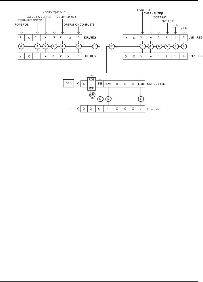
Status Model
Power on Settings
The following instrument status values are set at power on:
Status Byte Register |
= 0 |
Service Request Enable Register † |
= 0 |
Standard Event Status Register |
= 128 (pon bit set) |
Standard Event Status Enable Register † |
= 0 |
Execution Error Register |
= 0 |
Query Error Register |
= 0 |
Parallel Poll Enable Register † |
= 0 |
† Registers marked thus are specific to the GPIB section of the instrument and are of limited use in an RS232 environment.
The instrument will be in local state with the keyboard active.
The instrument parameters at power on are the same as at last switch off with the exception of the output status. By default this is always off at power on but the user may change this to the same at power on as at switch off.
29

Remote Commands
RS232 Remote Command Formats
Serial input to the instrument is buffered in a 256 byte input queue which is filled, under interrupt, in a manner transparent to all other instrument operations. The instrument will send XOFF when approximately 200 characters are in the queue. XON will be sent when approximately 100 free spaces become available in the queue after XOFF was sent. This queue contains raw (unparsed) data which is taken, by the parser, as required. Commands (and queries) are executed in order and the parser will not start a new command until any previous command or query is complete. In non–addressable RS232 mode responses to commands or queries are sent immediately; there is no output queue. In addressable mode the response formatter will wait indefinitely if necessary, until the instrument is addressed to talk and the complete response message has been sent, before the parser is allowed to start the next command in the input queue.
Commands must be sent as specified in the commands list and must be terminated with the command terminator code 0AH (Line Feed, LF). Commands may be sent in groups with individual commands separated from each other by the code 3BH (;). The group must be terminated with command terminator 0AH (Line Feed, LF).
Responses from the instrument to the controller are sent as specified in the commands list. Each re sponse is terminated by 0DH (Carriage Return, CR) followed by 0AH (Line Feed, LF).
<WHITE SPACE> is defined as character codes 00H to 20H inclusive with the exception of those which are specified as addressable RS232 control codes.
<WHITE SPACE> is ignored except in command identifiers. e.g. '*C LS' is not equivalent to '*CLS'. The high bit of all characters is ignored.
The commands are case insensitive.
GPIB Remote Command Formats
GPIB input to the instrument is buffered in a 256 byte input queue which is filled, under interrupt, in a manner transparent to all other instrument operations. The queue contains raw (un-parsed) data which is taken, by the parser, as required. Commands (and queries) are executed in order and the parser will not start a new command until any previous command or query is complete. There is no output queue which means that the response formatter will wait, indefinitely if necessary, until the instrument is addressed to talk and the complete response message has been sent, before the parser is allowed to start the next command in the input queue.
Commands are sent as <PROGRAM MESSAGES> by the controller, each message consisting of zero or more <PROGRAM MESSAGE UNIT> elements separated by <PROGRAM MESSAGE UNIT SEPARATOR> elements.
A <PROGRAM MESSAGE UNIT> is any of the commands in the remote commands list. A <PROGRAM MESSAGE UNIT SEPARATOR> is the semi-colon character ';' (3BH).
<PROGRAM MESSAGES> are separated by <PROGRAM MESSAGE TERMINATOR> elements which may be any of the following:
NL |
The new line character (0AH) |
NL^END |
The new line character with the END message |
^END |
The END message with the last character of the message |
Responses from the instrument to the controller are sent as <RESPONSE MESSAGES>. A
<RESPONSE MESSAGE> consists of one <RESPONSE MESSAGE UNIT> followed by a <RESPONSE MESSAGE TERMINATOR>.
A <RESPONSE MESSAGE TERMINATOR> is the new line character with the END message NL^END.
30
Loading...