


HPD 15-20
Table of contents
 Loading...
Operating Manual
HPD 300 Watt Series
Programmable DC
Power Supply
HPD 15-20
HPD 30-10
HPD 60-5


Operating Manual for
HPD Series
Programmable DC
Power Supply

ii Operating Manual for HPD Series Power Supply
Limited
Warranty
What does this warranty cover and how long does it last?
This Limited Warranty is provided by Xantrex Technology, Inc. (“Xantrex”) and
covers defects in workmanship and materials in your HPD 300 Watt Series DC
Power Supply. This warranty lasts for a Warranty Period of 5 years from the date
of purchase at point of sale to you, the original end user customer.
What will Xantrex do?
Xantrex will, at its option, repair or replace the defective product free of charge,
provided that you notify Xantrex of the product defect within the Warranty Period,
and provided that Xantrex through inspection establishes the existence of such a
defect and that it is covered by this Limited Warranty.
Xantrex will, at its option, use new and/or reconditioned parts in performing
warranty repair and building replacement products. Xantrex reserves the right to use
parts or products of original or improved design in the repair or replacement. If
Xantrex repairs or replaces a product, its warranty continues for the remaining
portion of the original Warranty Period or 90 days from the date of the return
shipment to the customer, whichever is greater. All replaced products and all parts
removed from repaired products become the property of Xantrex.
Xantrex covers both parts and labor necessary to repair the product, and return
shipment to the customer via a Xantrex-selected non-expedited surface freight
within the contiguous United States and Canada. Alaska and Hawaii are excluded.
Contact Xantrex Customer Service for details on freight policy for return shipments
outside of the contiguous United States and Canada.
How do you get service?
If your product requires troubleshooting or warranty service, contact your merchant.
If you are unable to contact your merchant, or the merchant is unable to provide
service, contact Xantrex directly at:
Phone: 604 422 8595
Toll Free North America: 1 800 667 8422
Fax: 604 421 3056
Email: info@xantrex.com

Release 1.2 iii
Direct returns may be performed according to the Xantrex Return Material
Authorization Policy described in your product manual. For some products, Xantrex
maintains a network of regional Authorized Service Centers. Call Xantrex or check
our website to see if your product can be repaired at one of these facilities.
In any warranty claim, dated proof of purchase must accompany the product and the
product must not have been disassembled or modified without prior written
authorization by Xantrex.
Proof of purchase may be in any one of the following forms:
• The dated purchase receipt from the original purchase of the product at point of
sale to the end user, or
• The dated dealer invoice or purchase receipt showing original equipment
manufacturer (OEM) status, or
• The dated invoice or purchase receipt showing the product exchanged under
warranty
What does this warranty not cover?
This Limited Warranty does not cover normal wear and tear of the product or costs
related to the removal, installation, or troubleshooting of the customer’s electrical
systems. This warranty does not apply to and Xantrex will not be responsible for any
defect in or damage to:
a. the product if it has been misused, neglected, improperly installed, physically
damaged or altered, either internally or externally, or damaged from improper
use or use in an unsuitable environment;
b. the product if it has been subjected to fire, water, generalized corrosion,
biological infestations, and high input voltage from lightning strikes;
c. the product if repairs have been done to it other than by Xantrex or its authorized
service centers (hereafter “ASCs”);
d. the product if it is used as a component part of a product expressly warranted by
another manufacturer;
e. the product if its original identification (trade-mark, serial number) markings
have been defaced, altered, or removed.

iv Operating Manual for HPD Series Power Supply
Disclaimer Product
THIS LIMITED WARRANTY IS THE SOLE AND EXCLUSIVE WARRANTY PROVIDED
BY XANTREX IN CONNECTION WITH YOUR XANTREX PRODUCT AND IS, WHERE
PERMITTED BY LAW, IN LIEU OF ALL OTHER WARRANTIES, CONDITIONS,
GUARANTEES, REPRESENTATIONS, OBLIGATIONS AND LIABILITIES, EXPRESS
OR IMPLIED, STATUTORY OR OTHERWISE IN CONNECTION WITH THE PRODUCT,
HOWEVER ARISING (WHETHER BY CONTRACT, TORT, NEGLIGENCE, PRINCIPLES
OF MANUFACTURER’S LIABILITY, OPERATION OF LAW, CONDUCT, STATEMENT
OR OTHERWISE), INCLUDING WITHOUT RESTRICTION ANY IMPLIED WARRANTY
OR CONDITION OF QUALITY, MERCHANTABILITY OR FITNESS FOR A
PARTICULAR PURPOSE. ANY IMPLIED WARRANTY OF MERCHANTABILITY OR
FITNESS FOR A PARTICULAR PURPOSE TO THE EXTENT REQUIRED UNDER
APPLICABLE LAW TO APPLY TO THE PRODUCT SHALL BE LIMITED IN DURATION
TO THE PERIOD STIPULATED UNDER THIS LIMITED WARRANTY.
IN NO EVENT WILL XANTREX BE LIABLE FOR ANY SPECIAL, DIRECT, INDIRECT,
INCIDENTAL OR CONSEQUENTIAL DAMAGES, LOSSES, COSTS OR EXPENSES
HOWEVER ARISING WHETHER IN CONTRACT OR TORT INCLUDING WITHOUT
RESTRICTION ANY ECONOMIC LOSSES OF ANY KIND, ANY LOSS OR DAMAGE TO
PROPERTY, ANY PERSONAL INJURY, ANY DAMAGE OR INJURY ARISING FROM OR
AS A RESULT OF MISUSE OR ABUSE, OR THE INCORRECT INSTALLATION,
INTEGRATION OR OPERATION OF THE PRODUCT.
Exclusions If this product is a consumer product, federal law does not allow an exclusion of
implied warranties. To the extent you are entitled to implied warranties under federal
law, to the extent permitted by applicable law they are limited to the duration of this
Limited Warranty. Some states and provinces do not allow limitations or exclusions
on implied warranties or on the duration of an implied warranty or on the limitation
or exclusion of incidental or consequential damages, so the above limitation(s) or
exclusion(s) may not apply to you. This Limited Warranty gives you specific legal
rights. You may have other rights which may vary from state to state or province to
province.

Release 1.2 v
Information WITHOUT LIMITING THE GENERALITY OF THE FOREGOING, UNLESS
SPECIFICALLY AGREED TO BY IT IN WRITING, XANTREX
a. MAKES NO WARRANTY AS TO THE ACCURACY, SUFFICIENCY OR SUITABILITY
OF ANY TECHNICAL OR OTHER INFORMATION PROVIDED IN MANUALS OR
OTHER DOCUMENTATION PROVIDED BY IT IN CONNECTION WITH THE
PRODUCT; AND
b. ASSUMES NO RESPONSIBILITY OR LIABILITY FOR LOSSES, DAMAGES,
COSTS OR EXPENSES, WHETHER SPECIAL, DIRECT, INDIRECT,
CONSEQUENTIAL OR INCIDENTAL, WHICH MIGHT ARISE OUT OF THE USE OF
SUCH INFORMATION.
THE USE OF ANY SUCH INFORMATION WILL BE ENTIRELY AT THE USER’S RISK.
WARNING:
Limitations
on Use
Please refer to your product user manual for limitations on uses of the product.
Specifically, please note that this power supply is not intended for use in connection
with life support systems and Xantrex makes no warranty or representation in
connection with any use of the product for such purposes.
Xantrex Technology, Inc.
8999 Nelson Way
Burnaby, British Columbia
Canada V5A 4B5
Information
About Your
Power
Supply
Please record the following information when you first open your Power Supply
package:
Release Release 1.2 (2003-04)
Copyright
©
2002 Xantrex Technology Inc. All rights reserved.
Printed in Canada
Model Number ______________________________________________
Serial Number ______________________________________________
Purchased From ______________________________________________
Purchase Date ______________________________________________

vi Operating Manual for HPD Series Power Supply
Warnings
and
Cautions
Warnings and cautions are defined and formatted in this manual as shown below.
Power
Supply
Safety
WARNING
Describes a potential hazard which could result in injury or death, or, a procedure
which, if not performed correctly, could result in injury or death.
!
CAUTION
Describes a procedure which, if not performed correctly, could result in damage
to data, equipment, or systems.
WARNING—High Energy and High Voltage
Exercise caution when using and calibrating a power supply. High energy levels
can be stored at the output voltage terminals on a power supply in normal
operation. In addition, potentially lethal voltages exist in the power circuit and on
the output and sense connectors of a power supply with a rated output greater
than 40 V. Filter capacitors store potentially dangerous energy for some time after
power is removed.
!
CAUTION
Operate the power supply in an environment free of flammable gases or fumes. To
ensure that the power supply’s safety features are not compromised, use the
power supply as specified in this manual and do not substitute parts or make any
unauthorized modifications. Contact the service technician for service and repair
help. Repairs must be made by experienced service technicians only.
!
CAUTION
For Use as a Battery Charger
When you are using any of these power supplies for battery charging applications,
it is essential to provide an appropriately sized fuse or circuit breaker in series
between the power supply output and the battery.
Installation of a protector (fuse or DC circuit breaker) rated for about 115% of the
maximum current rating of the power supply and designed specifically to interrupt
the DC voltage of the battery, will provide adequate reverse polarity current
protection. Where several power supplies are in parallel, it is best to fuse each one,
rather than one large fuse for all.

Release 1.2 vii
About This Manual
This Operating Manual contains operating instructions for the HPD Series of high
performance, switching, laboratory power supplies, available in several voltage
models at 300 watts. It provides information on features and specifications,
installation procedures, and basic functions testing, as well as operating procedures
for using both standard and multiple supply configurations.
Who Should Use This Manual
This manual is designed for the user who is familiar with basic electrical theory,
especially as applied to the operation of power supplies. This implies a recognition
of Constant Voltage and Constant Current operating modes and the control of input
and output power, as well as the observance of safe techniques while calibrating,
making supply connections, and/or making any changes in configuration.
Main Sections
Section 1 Features and Specifications Describes the power supply, lists its
features, and provides tables of specifications.
Section 2 Installation Reviews safety and inspection procedures, and provides
procedures for basic setup. Also includes directions for testing basic functions.
Section 3 Load Operation and Sensing Provides procedures for connecting
the load, grounding, and remote sensing.
Section 4 Operation Describes standard operation (Constant Voltage and
Constant Current), and series, parallel, and split supply operation.
Manual Revisions
The current release of this manual is listed below. Updates may be issued as an
addendum.
Release 1.2 (2003-04)

About This Manual
viii Operating Manual for HPD Series Power Supply
Power Supply Safety Markings
Alternating Current Off (Supply)
Earth (Ground) Terminal Caution (Hot Surface)
Protective Conductor Terminal Caution (Check manual for
additional information.)
On (Supply)

Release 1.2 ix
Contents
About This Manual . . . . . . . . . . . . . . . . . . . . . . . . . . . . . . . . . . . . . . . . . . . . . . . . . . . vii
Section 1.
Features and
Specifications
Introduction. . . . . . . . . . . . . . . . . . . . . . . . . . . . . . . . . . . . . . . . . . . . . . . . . . . . . . . . . 11
Features . . . . . . . . . . . . . . . . . . . . . . . . . . . . . . . . . . . . . . . . . . . . . . . . . . . . . . . . . . . 11
Options and Accessories . . . . . . . . . . . . . . . . . . . . . . . . . . . . . . . . . . . . . . . . . . . . . . 12
Front Panel Controls. . . . . . . . . . . . . . . . . . . . . . . . . . . . . . . . . . . . . . . . . . . . . . . . . . 12
Rear Panel Connectors and Outputs . . . . . . . . . . . . . . . . . . . . . . . . . . . . . . . . . . . . . 13
Electrical Specifications . . . . . . . . . . . . . . . . . . . . . . . . . . . . . . . . . . . . . . . . . . . . . . . 14
Additional Electrical Specifications . . . . . . . . . . . . . . . . . . . . . . . . . . . . . . . . . . . . . . . 15
Input Conditions . . . . . . . . . . . . . . . . . . . . . . . . . . . . . . . . . . . . . . . . . . . . . . . . . . . . .15
Electrical Characteristics . . . . . . . . . . . . . . . . . . . . . . . . . . . . . . . . . . . . . . . . . . . . . . 16
Environmental Specifications . . . . . . . . . . . . . . . . . . . . . . . . . . . . . . . . . . . . . . . . . . . 16
Mechanical Specifications . . . . . . . . . . . . . . . . . . . . . . . . . . . . . . . . . . . . . . . . . . . . . 17
Chassis Dimensions and Weight . . . . . . . . . . . . . . . . . . . . . . . . . . . . . . . . . . . . . . . . 18
Single Output Unit . . . . . . . . . . . . . . . . . . . . . . . . . . . . . . . . . . . . . . . . . . . . . . . 18
Dual Output Unit. . . . . . . . . . . . . . . . . . . . . . . . . . . . . . . . . . . . . . . . . . . . . . . . . 18
Section 2.
Installation
Introduction. . . . . . . . . . . . . . . . . . . . . . . . . . . . . . . . . . . . . . . . . . . . . . . . . . . . . . . . . 19
Basic Setup Procedure . . . . . . . . . . . . . . . . . . . . . . . . . . . . . . . . . . . . . . . . . . . . . . . . 19
Initial Inspection . . . . . . . . . . . . . . . . . . . . . . . . . . . . . . . . . . . . . . . . . . . . . . . . . . . . . 19
Periodic Cleaning. . . . . . . . . . . . . . . . . . . . . . . . . . . . . . . . . . . . . . . . . . . . . . . . 19
Returning Power Supplies to the Manufacturer . . . . . . . . . . . . . . . . . . . . . . . . . . . . . 20
Return Material Authorization Policy . . . . . . . . . . . . . . . . . . . . . . . . . . . . . . . . . 20
Packaging for Shipping or Storage . . . . . . . . . . . . . . . . . . . . . . . . . . . . . . . . . . 21
Rack Mounting . . . . . . . . . . . . . . . . . . . . . . . . . . . . . . . . . . . . . . . . . . . . . . . . . . . . . . 22
Location and Ventilation . . . . . . . . . . . . . . . . . . . . . . . . . . . . . . . . . . . . . . . . . . . . . . . 22
AC Input Power Connection . . . . . . . . . . . . . . . . . . . . . . . . . . . . . . . . . . . . . . . . . . . . 23
AC Input Cord . . . . . . . . . . . . . . . . . . . . . . . . . . . . . . . . . . . . . . . . . . . . . . . . . . 23
Functional Tests . . . . . . . . . . . . . . . . . . . . . . . . . . . . . . . . . . . . . . . . . . . . . . . . . . . . . 24
Power-on Check. . . . . . . . . . . . . . . . . . . . . . . . . . . . . . . . . . . . . . . . . . . . . . . . . 24
Voltage Mode Operation Check. . . . . . . . . . . . . . . . . . . . . . . . . . . . . . . . . . . . . 24
Current Mode Operation Check . . . . . . . . . . . . . . . . . . . . . . . . . . . . . . . . . . . . . 24
Section 3.
Load
Connection
and Sensing
Introduction. . . . . . . . . . . . . . . . . . . . . . . . . . . . . . . . . . . . . . . . . . . . . . . . . . . . . . . . . 25
Load Connection. . . . . . . . . . . . . . . . . . . . . . . . . . . . . . . . . . . . . . . . . . . . . . . . . . . . . 25
Load Wiring . . . . . . . . . . . . . . . . . . . . . . . . . . . . . . . . . . . . . . . . . . . . . . . . . . . . 26
Making Load Connections . . . . . . . . . . . . . . . . . . . . . . . . . . . . . . . . . . . . . . . . .28
Connecting Multiple Loads. . . . . . . . . . . . . . . . . . . . . . . . . . . . . . . . . . . . . . . . . 28
Grounding . . . . . . . . . . . . . . . . . . . . . . . . . . . . . . . . . . . . . . . . . . . . . . . . . . . . . . . . . . 29
Local Sensing . . . . . . . . . . . . . . . . . . . . . . . . . . . . . . . . . . . . . . . . . . . . . . . . . . . . . . . 29
Output Jumpers for Local Sensing. . . . . . . . . . . . . . . . . . . . . . . . . . . . . . . . . . . 29
Remote Sensing . . . . . . . . . . . . . . . . . . . . . . . . . . . . . . . . . . . . . . . . . . . . . . . . . . . . . 31

Contents
x
Operating Manual for HPD Series Power Supply
Section 4.
Operation
Introduction . . . . . . . . . . . . . . . . . . . . . . . . . . . . . . . . . . . . . . . . . . . . . . . . . . . . . . . . 33
Operating Modes . . . . . . . . . . . . . . . . . . . . . . . . . . . . . . . . . . . . . . . . . . . . . . . . . . . . 33
Constant Voltage Mode Operation . . . . . . . . . . . . . . . . . . . . . . . . . . . . . . . . . . 34
Constant Current Mode Operation . . . . . . . . . . . . . . . . . . . . . . . . . . . . . . . . . . 34
Setting the Current Limit . . . . . . . . . . . . . . . . . . . . . . . . . . . . . . . . . . . . . . . . . . 34
Setting the Supply to Operate in CI Mode. . . . . . . . . . . . . . . . . . . . . . . . . . . . . 34
Automatic Mode Crossover. . . . . . . . . . . . . . . . . . . . . . . . . . . . . . . . . . . . . . . . 35
Constant Power Loads . . . . . . . . . . . . . . . . . . . . . . . . . . . . . . . . . . . . . . . . . . . 35
Using Multiple Supplies . . . . . . . . . . . . . . . . . . . . . . . . . . . . . . . . . . . . . . . . . . . . . . . 36
Connecting Multiple Supplies in Series (Voltage Mode Only) . . . . . . . . . . . . . . 36
Connecting Multiple Supplies in Parallel . . . . . . . . . . . . . . . . . . . . . . . . . . . . . . 37
Split Supply Operation. . . . . . . . . . . . . . . . . . . . . . . . . . . . . . . . . . . . . . . . . . . . 38

Release 1.2 11
Section 1. Features and Specifications
Introduction
The HPD Series of DC power supplies provides highly stable, variable output
voltage and current for a broad range of development and system requirements.
These units employ high frequency switching regulator technology to achieve high
power density and small package size, as well as a linear post-regulator circuit for
low output noise and fast response. A wide variety of options is available, including
both analog and IEEE-488 controlled programming, to make this series the first
choice in flexible power system design.
Table 1.1 300 Watt Series Models
Features
• High frequency switching technology allows high power density, providing
increased power output in a small, light, package.
• The power supply delivers simultaneous digital displays for both voltage and
current, and bar graph displays for monitoring transient changes, which gives the
user the benefit of continuous, up-to-date information.
• Ten-turn voltage control permits high resolution setting of the output voltage.
• Current limit is fully adjustable from zero to the rated output with a single turn
control.
• The automatic crossover system allows the power supply to automatically
switch operating modes into current or voltage mode.
• Impedance-switched remote sensing lets operators display the voltage at the load
with no switch ambiguity.
• Multiple units can be connected in parallel or series to produce greater diversity.
• Short-circuit-proof power outlets give greater operating safety.
• These power supplies (available in single and dual outputs) can be combined
with one or more 60 watt series power supplies to create mixed units that are
ideal for high precision applications.
Model Output Voltage Output Current
15–20 0–15 V 0–20 A
30–10 0–30 V 0–10 A
60–5 0–60 V 0–5 A
Section 1. Features and Specifications
Options and Accessories
12 Operating Manual for HPD Series Power Supply
Options and Accessories
• Internal Analog Programming (APG) interface for analog signal control of
voltage and current, overvoltage protection (OVP), master/slave output tracking,
and remote ON/OFF.
• Internal RS-232 interface for serial instrument programming using RS-232
protocol.
• Internal GPIB interface for complete remote digital programming. IEEE-488
standard.
• Optional 200–250 Vac input (Option AC200). Standard is 115 Vac. Optional AC
input cords for use in different countries.
• Ten-turn current potentiometer (Option M11). Rack mount kit (Option RM).
• Locking voltage and/or current adjust knobs (Option M13A).
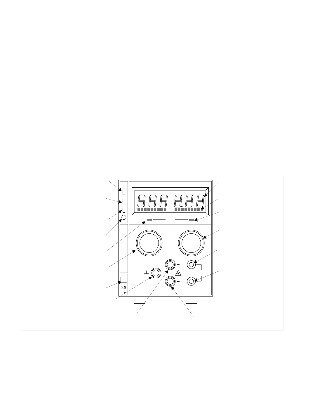
Front Panel Controls
Figure 1.1 shows the controls, LEDs, and meters located on the unit’s front panel.
Figure 1.1 Front Panel Controls
REGULATED DC POWER SUPPLY
MODE
VOLTAGE CURRENT
SENSE
POWER
P
G
S
/
D
O
V
P
OVP
ADJ
M
Shutdown LED (S/D)
(For units with APG installed.)
Voltage Mode
Indicator (Green LED)
Safety Ground
Binding Post (Green)
AC Power Switch
Positive (+) Output Binding Post (Red)
Voltage Control Knob
(10-turn standard)
OVP Shutdown (OVP)
(For units with APG installed.)
OVP Adjust Potentiometer (OVP ADJ)
(For units with APG installed.)
Digital Display of DC Output
(Volts, Amperes)
Analog Bar Graph Display
Current Limit Mode
Indicator (Red LED)
Current Limit Adjust Knob
(1-turn standard)
Positive (+) Sense
Connection
(Banana Jack)
Return (−) Sense
Connection
(Banana Jack)
Return (−) Output Binding
Post (Black)
Remote Programming LED (PGM)
(For units with APG installed.
See also Figure 1.2).
Loading...