


DCCB-L
DCCB-L-175
DCCB-L-250
Owner’s Guide
Sine Wave Plus DC
Conduit Box Long

Sine Wave Plus Long DC Conduit
Box
Owner’s Guide
About Xantrex
Xantrex Technology Inc. is a world-leading supplier of advanced power electronics and controls with products from 50 watt mobile units to one MW utility-scale systems for wind, solar, batteries, fuel cells, microturbines, and backup power applications in both grid-connected and stand-alone systems. Xantrex products include inverters, battery chargers, programmable power supplies, and variable speed drives that convert, supply, control, clean, and distribute electrical power.
Trademarks
Sine Wave Plus Long DC Conduit Box is a trademark of Xantrex International. Xantrex is a registered trademark of Xantrex International.
Other trademarks, registered trademarks, and product names are the property of their respective owners and are used herein for identification purposes only.
Notice of Copyright
Sine Wave Plus Long DC Conduit Box (DCCB-L) Owner’s Guide © July 2004 Xantrex International. All rights reserved.
Disclaimer
UNLESS SPECIFICALLY AGREED TO IN WRITING, XANTREX TECHNOLOGY INC. (“XANTREX”)
(a)MAKES NO WARRANTY AS TO THE ACCURACY, SUFFICIENCY OR SUITABILITY OF ANY TECHNICAL OR OTHER INFORMATION PROVIDED IN ITS MANUALS OR OTHER DOCUMENTATION.
(b)ASSUMES NO RESPONSIBILITY OR LIABILITY FOR LOSS OR DAMAGE, WHETHER DIRECT, INDIRECT, CONSEQUENTIAL OR INCIDENTAL, WHICH MIGHT ARISE OUT OF THE USE OF SUCH INFORMATION. THE USE OF ANY SUCH INFORMATION WILL BE ENTIRELY AT THE USER’S RISK.
Date and Revision
July 2004 Revision A
Part Number
973-0032-01-01 Rev A
Contact Information
Telephone: |
1 800 670 0707 |
(toll free North America) |
|
1 360 925 5097 |
(direct) |
Fax: |
1 800 994 7828 |
(toll free North America) |
|
1 360 925 5143 |
(direct) |
Email: |
customerservice@xantrex.com |
|
Web: |
www.xantrex.com |
|

About This Guide
Purpose
The purpose of this Owner’s Guide is to provide explanations and procedures for installing the Long DC Conduit Box (DCCB-L) on a Sine Wave Inverter/charger.
Scope
The Owner’s Guide provides safety guidelines and procedures for installing the Long DC Conduit Box.
Audience
The information in this Guide is intended for the experienced electrician who need to install the Long DC Conduit Box into a power system. Only skilled personnel, such as certified electricians and certified Renewable Energy technicians should attempt installation of this equipment. Skills required include the ability to read and understand how to follow single-line wiring diagrams.
Organization
This Guide consists of two chapters.
Chapter 1, “Introduction” provides basic information about the design and purpose of the Sine Wave Plus Long DC Conduit Box.
Chapter 2, “Installation” provides installation and wiring instructions for the Sine Wave Plus Long DC Conduit Box (DCCB-L).
Warranty and Product Information is provided at the end of the manual.
973-0032-01-01 Rev A |
iii |
About This Guide
Conventions Used
The following conventions are used in this guide.
WARNING
Warnings identify conditions that could result in personal injury or loss of life.
CAUTION
Cautions identify conditions or practices that could result in damage to the unit or other equipment.
Important: These notes describe things which are important for you to know, but not as serious as a caution or warning.
Product Naming Conventions
DCCB-L refers to the Long DC Conduit Box without any factory installed wiring.
DCCB-L-175/L-250 refers to the Long DC Conduit Box with either a GJ175F or a GJ250F Circuit Breaker installed. It includes some factory-installed wiring.
DCCB-RE describes a field-installed, dual-conduit box installation intended for supporting multiple RE sources.
Long DC Conduit Box refers to all products and is used in situations where all three products are treated the same.
iv |
973-0032-01-01 Rev A |

About This Guide
Abbreviations and Acronyms
AC |
Alternating Current |
AHJ |
Authority Having Jurisdiction |
ASC |
Authorized Service Center |
AWG |
American Wire Gauge |
BSM |
Battery Status Meter |
BTS |
Battery Temperature Sensor |
CEC |
Canadian Electrical Code |
CSA |
Canadian Standards Association |
DC |
Direct Current |
DCCB-L |
DC Conduit Box Long Version for the SW Plus Inverter/Charger |
DCCB-L-175/L-250 A DCCB-L that includes factory-installed hardware. |
|
PVGFP |
PV Ground Fault Protection |
NEC |
National Electrical Code (US) |
RE |
Renewable Energy |
RMA |
Return Material Authorization |
UL |
Underwriters Laboratory |
Related Information
You can find more information about Xantrex Technology Inc. as well as its products and services at www.xantrex.com.
973-0032-01-01 Rev A |
v |
vi

Important Safety Instructions
 WARNING
This chapter contains important safety and operating instructions for the Sine Wave Plus Long DC Conduit Box (all models). Read and keep this Installation Guide for future reference.
1.Installations of this equipment should only be performed by skilled personnel such as qualified electricians and certified Renewable Energy (RE) system installers to ensure adherence to the local and national electrical codes applicable in your installation. For a list of Xantrex Certified RE dealers, please visit our website at www.xantrexREdealers.com.
2.Before installing any components, read all instructions and cautionary markings on the Long DC Conduit Box, the batteries, and all appropriate sections of this guide.
3.The Long DC Conduit Box is designed to be permanently connected to your Sine Wave Plus inverter to prevent accidental exposure to shock hazards.
4.Do not expose the Long DC Conduit Box to rain, snow, or spray. To reduce risk of fire hazard, do not cover or obstruct the ventilation openings.
5.Do not install the Long DC Conduit Box in a zero-clearance compartment. The Sine Wave Plus inverter that is attached may overheat. Minimum clearance for ventilation around unit must be 12 inches (305 mm) at the end and the top.
6.To avoid a risk of fire and electric shock, make sure that existing wiring is in good condition and that wire is not undersized. Do not operate the inverter with damaged or substandard wiring.
7.To reduce the risk of electrical shock, disconnect both AC and DC power from the system before attempting any maintenance or cleaning or working on the Long DC Conduit Box.
8.The Long DC Conduit Box is provided with an equipment-grounding bar that must be connected to the inverter equipment ground and the system ground.
9.Do not store any flammable materials near the primary system panel.
973-0032-01-01 Rev A |
vii |

Safety
Explosive gas precautions
1.Working in the vicinity of lead-acid batteries is dangerous. Batteries generate explosive gases during normal operation. Therefore you must read this guide and follow the instructions exactly before installing the DCCB-L.
2.To reduce the risk of battery explosion, follow these instructions and those published by the battery manufacturer and the manufacturer of the equipment in which the battery is installed.
Certifications
CSA certified to the following standards:
•UL 1741-2001 First Edition, and
•CSA C22.2 No. 107.1-01
viii |
973-0032-01-01 Rev A |
Contents
Important Safety Instructions - - - - - - - - - - - - - - - - - - - - - - - - - - - - - - - - - - - - - - - - - - -vii
1 Introduction
Introduction - - - - - - - - - - - - - - - - - - - - - - - - - - - - - - - - - - - - - - - - - - - - - - - - - - - - - - - - - - 1–2
Specifications - - - - - - - - - - - - - - - - - - - - - - - - - - - - - - - - - - - - - - - - - - - - - - - - - - - - - - - - - 1–3
Blockoff Plates - - - - - - - - - - - - - - - - - - - - - - - - - - - - - - - - - - - - - - - - - - - - - - - - - - - - - - - - 1–5
Options/Accessories- - - - - - - - - - - - - - - - - - - - - - - - - - - - - - - - - - - - - - - - - - - - - - - - - - - - - 1–6
Charge Controllers or Diversion Load Controllers - - - - - - - - - - - - - - - - - - - - - - - - - - - - - - 1–6
Charge Controller Installation Package - - - - - - - - - - - - - - - - - - - - - - - - - - - - - - - - - - - - - 1–7
PV Ground Fault Protection (PVGFP-CF) - - - - - - - - - - - - - - - - - - - - - - - - - - - - - - - - - - - 1–8
GJ175F and GJ250F Breakers and Flag Terminals - - - - - - - - - - - - - - - - - - - - - - - - - - - - - 1–8
CF60 Circuit Breakers - - - - - - - - - - - - - - - - - - - - - - - - - - - - - - - - - - - - - - - - - - - - - - - 1–10
CF-Series Breaker Mounting Plate - - - - - - - - - - - - - - - - - - - - - - - - - - - - - - - - - - - - - - - 1–10
Power Distribution Blocks (PDB) - - - - - - - - - - - - - - - - - - - - - - - - - - - - - - - - - - - - - - - - 1–10
Battery Status Monitor (BSM) - - - - - - - - - - - - - - - - - - - - - - - - - - - - - - - - - - - - - - - - - - 1–11
Battery Temperature Sensors - - - - - - - - - - - - - - - - - - - - - - - - - - - - - - - - - - - - - - - - - - - 1–12
Battery Cables - - - - - - - - - - - - - - - - - - - - - - - - - - - - - - - - - - - - - - - - - - - - - - - - - - - - - 1–12
DC Negative Bus Bar - - - - - - - - - - - - - - - - - - - - - - - - - - - - - - - - - - - - - - - - - - - - - - - - 1–13
2 Installation
Preparing for the Installation - - - - - - - - - - - - - - - - - - - - - - - - - - - - - - - - - - - - - - - - - - - - - - - 2–2 Code Compliance - - - - - - - - - - - - - - - - - - - - - - - - - - - - - - - - - - - - - - - - - - - - - - - - - - - - 2–2 Installation Tools and Materials - - - - - - - - - - - - - - - - - - - - - - - - - - - - - - - - - - - - - - - - - - 2–2 Pre-installation - - - - - - - - - - - - - - - - - - - - - - - - - - - - - - - - - - - - - - - - - - - - - - - - - - - - - - - - 2–3 Location - - - - - - - - - - - - - - - - - - - - - - - - - - - - - - - - - - - - - - - - - - - - - - - - - - - - - - - - - - 2–3 Service Planning - - - - - - - - - - - - - - - - - - - - - - - - - - - - - - - - - - - - - - - - - - - - - - - - - - - - 2–3 Ventilation Requirements - - - - - - - - - - - - - - - - - - - - - - - - - - - - - - - - - - - - - - - - - - - - - - 2–4 Removing and Replacing the Long DC Conduit Box Cover - - - - - - - - - - - - - - - - - - - - - - - 2–5 Installing or Removing the Blockoff Plates - - - - - - - - - - - - - - - - - - - - - - - - - - - - - - - - - - 2–6 Knockout Preparation - - - - - - - - - - - - - - - - - - - - - - - - - - - - - - - - - - - - - - - - - - - - - - - - - 2–7 Mounting - - - - - - - - - - - - - - - - - - - - - - - - - - - - - - - - - - - - - - - - - - - - - - - - - - - - - - - - - - - - 2–8 Mounting the Long DC Conduit Box on the Xantrex Back Plate (XBP) - - - - - - - - - - - - - - - 2–8 Mounting on Plywood - - - - - - - - - - - - - - - - - - - - - - - - - - - - - - - - - - - - - - - - - - - - - - - - 2–10 Installing Accessories- - - - - - - - - - - - - - - - - - - - - - - - - - - - - - - - - - - - - - - - - - - - - - - - - - - 2–11 Dual DCCB-L Configurations (DCCB-L-RE) - - - - - - - - - - - - - - - - - - - - - - - - - - - - - - - - - - 2–13 Dual DCCB-Ls - - - - - - - - - - - - - - - - - - - - - - - - - - - - - - - - - - - - - - - - - - - - - - - - - - - - 2–13 Dual DCCB-L-175s (or L-250s) - - - - - - - - - - - - - - - - - - - - - - - - - - - - - - - - - - - - - - - - - 2–14
973-0032-01-01 Rev A |
ix |

Contents
Charge/Load Controllers - - - - - - - - - - - - - - - - - - - - - - - - - - - - - - - - - - - - - - - - - - - - - - - |
- -2–15 |
Wiring - General - - - - - - - - - - - - - - - - - - - - - - - - - - - - - - - - - - - - - - - - - - - - - - - - - - - - - |
-2–16 |
Grounding the Long DC Conduit Box - - - - - - - - - - - - - - - - - - - - - - - - - - - - - - - - - - - - |
-2–16 |
DC Equipment Grounding - - - - - - - - - - - - - - - - - - - - - - - - - - - - - - - - - - - - - - - - - |
-2–17 |
Bonding DC Negative to Ground - - - - - - - - - - - - - - - - - - - - - - - - - - - - - - - - - - - - - |
-2–18 |
Connecting to the Primary System Ground - - - - - - - - - - - - - - - - - - - - - - - - - - - - - - |
-2–18 |
Connecting DC and AC Electrical System Grounds Together - - - - - - - - - - - - - - - - - - |
-2–19 |
Over-current Protection - - - - - - - - - - - - - - - - - - - - - - - - - - - - - - - - - - - - - - - - - - - - - - |
-2–22 |
Master DC Disconnect - - - - - - - - - - - - - - - - - - - - - - - - - - - - - - - - - - - - - - - - - - - - - - - |
-2–23 |
Additional Over-current Protection - - - - - - - - - - - - - - - - - - - - - - - - - - - - - - - - - - - - - - |
-2–24 |
Battery Cable Connection - - - - - - - - - - - - - - - - - - - - - - - - - - - - - - - - - - - - - - - - - - - - - |
-2–25 |
Wiring - Specific - - - - - - - - - - - - - - - - - - - - - - - - - - - - - - - - - - - - - - - - - - - - - - - - - - - - - |
-2–27 |
Single Inverter System - - - - - - - - - - - - - - - - - - - - - - - - - - - - - - - - - - - - - - - - - - - - - - - |
-2–27 |
Single Inverter System with Renewable Energy - - - - - - - - - - - - - - - - - - - - - - - - - - - - - - |
-2–28 |
Dual Inverter System with Renewable Energy - - - - - - - - - - - - - - - - - - - - - - - - - - - - - - - |
-2–29 |
Dual Inverter System with Multiple Renewable Energy - - - - - - - - - - - - - - - - - - - - - - - - - |
-2–30 |
Additional Accessory Wiring - - - - - - - - - - - - - - - - - - - - - - - - - - - - - - - - - - - - - - - - - - |
-2–31 |
Battery Status Monitor (BSM) (p/n TM500A or TM500A-NS) - - - - - - - - - - - - - - - - - |
-2–31 |
Charge Controller Wiring using the C-Series Multifunction DC Controller |
|
and the CC PCK - - - - - - - - - - - - - - - - - - - - - - - - - - - - - - - - - - - - - - - - - - - - - - |
-2–32 |
Battery Temperature Sensor - - - - - - - - - - - - - - - - - - - - - - - - - - - - - - - - - - - - - - - - |
-2–33 |
Warranty and Return Information - - - - - - - - - - - - - - - - - - - - - - - - - - - - - - - - - - - |
WA–1 |
Index - - - - - - - - - - - - - - - - - - - - - - - - - - - - - - - - - - - - - - - - - - - - - - - - - - - - - - - - - - - - - - - |
IX–1 |
x |
973-0032-01-01 Rev A |

Figures
Figure 1-1 Sine Wave Plus Long DC Conduit Box - - - - - - - - - - - - - - - - - - - - - - - - - - - - - - - - - 1–2 Figure 1-2 Long DC Conduit Box Dimensions (Not To Scale)- - - - - - - - - - - - - - - - - - - - - - - - - - 1–4 Figure 1-3 The Blockoff Plates - - - - - - - - - - - - - - - - - - - - - - - - - - - - - - - - - - - - - - - - - - - - - - - 1–5 Figure 1-4 The C-Series Multi-function DC Controller Family - - - - - - - - - - - - - - - - - - - - - - - - - 1–7 Figure 1-5 Charge Controller Installation Package (CC PCK) - - - - - - - - - - - - - - - - - - - - - - - - - - 1–7 Figure 1-6 PVGFP-CF Breakers (-1, -2, -3 and -4)- - - - - - - - - - - - - - - - - - - - - - - - - - - - - - - - - - 1–8 Figure 1-7 GJ Breakers and Flag Terminals - - - - - - - - - - - - - - - - - - - - - - - - - - - - - - - - - - - - - - 1–9 Figure 1-8 GJ 175F-PCK or the GJ250F-PCK- - - - - - - - - - - - - - - - - - - - - - - - - - - - - - - - - - - - - 1–9 Figure 1-9 CF60 Circuit Breaker- - - - - - - - - - - - - - - - - - - - - - - - - - - - - - - - - - - - - - - - - - - - - 1–10 Figure 1-10 CF-Series Mounting Plate (CFMP) - - - - - - - - - - - - - - - - - - - - - - - - - - - - - - - - - - - 1–10 Figure 1-11 Power Distribution Blocks - - - - - - - - - - - - - - - - - - - - - - - - - - - - - - - - - - - - - - - - - 1–10 Figure 1-12 Battery Status Monitor - - - - - - - - - - - - - - - - - - - - - - - - - - - - - - - - - - - - - - - - - - - - 1–11 Figure 1-13 Battery Temperature Sensor - - - - - - - - - - - - - - - - - - - - - - - - - - - - - - - - - - - - - - - - 1–12 Figure 1-14 Battery Cable Set (BC-L2-250 or BC-L2-175)- - - - - - - - - - - - - - - - - - - - - - - - - - - - 1–12 Figure 1-15 DC Negative Bus Bar - - - - - - - - - - - - - - - - - - - - - - - - - - - - - - - - - - - - - - - - - - - - 1–13 Figure 2-1 Warning Label - - - - - - - - - - - - - - - - - - - - - - - - - - - - - - - - - - - - - - - - - - - - - - - - - - 2–3 Figure 2-2 Space and Clearance Requirements - - - - - - - - - - - - - - - - - - - - - - - - - - - - - - - - - - - - 2–4 Figure 2-3 Removing and Replacing the Long DC Conduit Box Top Cover- - - - - - - - - - - - - - - - - 2–5 Figure 2-4 The Blockoff Plates on the Long DC Conduit Box - - - - - - - - - - - - - - - - - - - - - - - - - - 2–6 Figure 2-5 Knockout Locations on the Long DC Conduit Box - - - - - - - - - - - - - - - - - - - - - - - - - - 2–7 Figure 2-6 The XBP Back Plate - - - - - - - - - - - - - - - - - - - - - - - - - - - - - - - - - - - - - - - - - - - - - - 2–8 Figure 2-7 Mounting the Long DC Conduit Box and the SW Plus Inverter Charger on the XBP - - - 2–9
Figure 2-8 Mounting the Long DC Conduit Box and the Sine Wave Plus Inverter Charger
on Plywood - - - - - - - - - - - - - - - - - - - - - - - - - - - - - - - - - - - - - - - - - - - - - - - - - - - 2–10 Figure 2-9 Installing Circuit Breakers on the Long DC Conduit Box - - - - - - - - - - - - - - - - - - - - 2–12 Figure 2-10 Optional Component Locations on the Long DC Conduit Box - - - - - - - - - - - - - - - - - 2–12 Figure 2-11 Creating a DCCB-L-RE Configuration from Dual DCCB-Ls - - - - - - - - - - - - - - - - - - 2–13 Figure 2-12 Creating a DCCB-L-RE Configuration from two DCCB-L-175 (or L-250)- - - - - - - - - 2–14 Figure 2-13 Adding Charge or Diversion Load Controllers on the Long DC Conduit Box - - - - - - - 2–15 Figure 2-14 Grounding Using PVGFP-CF - - - - - - - - - - - - - - - - - - - - - - - - - - - - - - - - - - - - - - - 2–20 Figure 2-15 Grounding Without PVGFP-CF- - - - - - - - - - - - - - - - - - - - - - - - - - - - - - - - - - - - - - 2–21 Figure 2-16 Battery Connections for a Single-inverter System- - - - - - - - - - - - - - - - - - - - - - - - - - 2–25 Figure 2-17 Battery Connections for a Dual-inverter System- - - - - - - - - - - - - - - - - - - - - - - - - - - 2–26 Figure 2-18 DC Wiring for a Single Inverter System - - - - - - - - - - - - - - - - - - - - - - - - - - - - - - - - 2–27 Figure 2-19 DC Wiring for a Single Inverter System with Renewable Energy - - - - - - - - - - - - - - - 2–28 Figure 2-20 DC Wiring for a Dual Inverter System with Renewable Energy - - - - - - - - - - - - - - - - 2–29
973-0032-01-01 Rev A |
xi |

Figures
Figure 2-21 DC Wiring for a Dual Inverters, Dual Long DC Conduit Box System with Multiple RE 2–30 Figure 2-22 Installing the BSM on the Long DC Conduit Box - - - - - - - - - - - - - - - - - - - - - - - - - -2–31
Figure 2-23 Wiring the C-Series Multifunction Charge Controllers to the Long DC Conduit Box
using the CC PCK - - - - - - - - - - - - - - - - - - - - - - - - - - - - - - - - - - - - - - - - - - - - - - -2–32 Figure 2-24 BTS Port locations on the Sine Wave Plus Inverter - - - - - - - - - - - - - - - - - - - - - - - - -2–33 Figure 2-25 BTS Port locations on the C-Series DC Controller- - - - - - - - - - - - - - - - - - - - - - - - - -2–33 Figure 2-26 Installing the Battery Temperature Sensor - - - - - - - - - - - - - - - - - - - - - - - - - - - - - - -2–34
xii |
973-0032-01-01 Rev A |

Tables
Table 1-1 Operational and Environmental Specifications for the Long DC Conduit Box- - - - - - - - 1–3 Table 2-1 Minimum Equipment Ground Wire and DC Disconnect Size Chart- - - - - - - - - - - - - - 2–17 Table 2-2 Recommended Battery Cable Size Versus Length - - - - - - - - - - - - - - - - - - - - - - - - - 2–22 Table 2-3 Battery Cable to Maximum Breaker/Fuse Size- - - - - - - - - - - - - - - - - - - - - - - - - - - - 2–22
973-0032-01-01 Rev A |
xiii |
xiv
1 Introduction
Chapter 1, “Introduction” provides basic information about the design and purpose of the Sine Wave Plus Long DC Conduit Box.
The following topics are covered in this chapter.
For this topic: |
See... |
|
|
“Introduction” |
page 1–2 |
“Specifications” |
page 1–3 |
“Blockoff Plates” |
page 1–5 |
“Options/Accessories” |
page 1–6 |
|
|
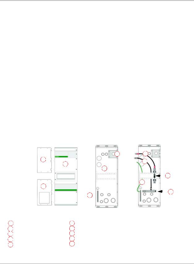
Introduction
Introduction
The Sine Wave Plus Long DC Conduit Box (DCCB-L) connects to the DC side of the inverter and accepts DC conduit runs. The conduit box provides protection to the DC cables connected to the inverter and provides a centralized location for the DC circuit breakers and PV Ground Fault Protection (GFP) breakers. It is also designed to incorporate cabling from up to two Multi-function DC Charge Controllers, such as the Xantrex C-Series Charge Controllers, and cabling from a battery meter, such as the Xantrex Battery Status Meter.
The Long DC Conduit Box is available in three different configurations.
•The DCCB-L Basic provides an internal ground bar only and space to add additional circuit breakers; three large and six small.
•The DCCB-L-175 includes a 175 amp GJ, F-Type, circuit breaker, a DC negative bus bar and 500A/50 mV shunt, battery cables (1 set) and a ground wire connected to the ground bar.
•The DCCB-L-250 includes a 250 amp GJ, F-type, circuit breaker a DC negative bus bar and 500A/50 mV shunt, battery cables (1 set) and a ground wire connected to the ground bar.
For expandability, the Long DC Conduit Box is designed so that a second DCCB- L (any model) can be added on for additional breaker spaces, wiring, room and controller mounting spaces. Dual configurations have been certified to meet UL1741-2001 (First Edition) standards when using the field-installable accessories as listed page 1–6.
Blockoff |
|
H |
|||||
Plates |
E |
||||||
Upper |
B |
I |
|||||
A |
|||||||
|
|
|
|
|
|
||
|
D |
|
|
|
|
|
|
|
|
|
|
|
F |
||
|
|
|
|
|
|||
|
B |
J |
|||||
|
|
|
|
|
|
||
Lower |
C |
|
|
|
|
G |
|
|
|
|
|
||||
|
|
|
|
|
|
||
|
Front Cover |
|
DCCB-L |
DCCB-L includes: |
DCCB-L-175 or DCCB-L-250 adds: |
||
A |
Front Cover |
F |
One GJ175F or GJ250F Circuit Breaker |
B Blockoff Plates (top and bottom) |
G |
DC Negative Bus Bar and Shunt |
|
C |
DC Ground Bar |
H |
One Positive (+) Battery Cable |
D |
6CF/3GJ Mounting Plate |
I |
One Negative (–) Battery Cable |
|
|||
E Battery Meter Mounting Box |
J |
One length green GROUND wire |
|
|
|||
Figure 1-1 Sine Wave Plus Long DC Conduit Box
DCCB-L-175 or DCCB-L-250
1–2 |
973-0032-01-01 Rev A |

Specifications
Specifications
The following table provides the operational and environmental specifications for the Long DC Conduit Box (all models).
Table 1-1 Operational and Environmental Specifications for the Long DC Conduit Box
|
DCCB-L Basic |
DCCB-L-175 |
DCCB-L-250 |
|
|
|
|
Dimensions |
33" (H) x 13 1/2" (W) x 8 7/8" (D) |
33" (H) x 13 1/2" (W) x 8 7/8" (D) |
33" (H) x 13 1/2" (W) x 8 7/8" (D) |
|
(384 mm x 343 mm x 225 mm) |
(384 mm x 343 mm x 225 mm) |
(384 mm x 343 mm x 225 mm) |
|
|
|
|
Weight |
22 lbs (10 kg) |
33 lbs (15 kg) |
33 lbs (15 kg) |
|
|
|
|
Shipping |
25 lbs (11.5 kg) |
36 lbs (16.5 kg) |
36 lbs (16.5 kg) |
Weight |
|
|
|
|
|
|
|
Factory- |
• DC Ground Bar (with 12 holes, |
• DC Ground Bar (with 12 holes, |
• DC Ground Bar (with 12 holes, |
installed |
accepts #2 - 14 AWG wires) |
accepts #2 - 14 AWG wires) |
accepts #2 - 14 AWG wires) |
hardware |
• 6CF/3GJ Mounting Plate |
• 6CF/3GJ Mounting Plate |
• 6CF/3GJ Mounting Plate |
|
• Mounting box for BSM (w cover) |
• Mounting box for BSM (w cover) |
• Mounting box for BSM (w cover) |
|
|
• DC Negative Bus Bar |
• DC Negative Bus Bar |
|
|
• 500 A/50 mV Shunt |
• 500 A/50 mV Shunt |
|
|
• GJ175F Circuit Breaker |
• GJ250F Circuit Breaker |
|
|
|
|
Factory- |
None |
• One - Ground Wire (#4 AWG, 18", |
• One - Ground Wire (#4 AWG, 18", |
installed |
|
rated to 105 °C, stranded copper) ( |
rated to 105 °C, stranded copper) |
wiring |
|
• One - Positive (+) Battery Cable |
• One - Positive (+) Battery Cable |
|
|
(#2/0 AWG, 16" Cable) |
(#4/0 AWG, 16" Cable) |
|
|
• One - Negative (–) Battery Cable |
• One - Negative (–) Battery Cable |
|
|
(#2/0 AWG, 30" Cable) |
(#4/0 AWG, 30" Cable) |
|
|
|
|
Rated |
0 to 25 °C |
0 to 25 °C |
0 to 25 °C |
Temperature |
(32 to 77 °F) |
(32 to 77 °F) |
(32 to 77 °F) |
|
|
|
|
Storage |
-55 to +100 °C |
-55 to +100 °C |
-55 to +100 °C |
Temperature |
(-67 to 212 °F) |
(-67 to 212 °F) |
(-67 to 212 °F) |
|
|
|
|
Enclosure |
Indoor rated, Galveneel, White, |
Indoor rated, Galveneel, White, |
Indoor rated, Galveneel, White, |
|
Powdercoat Finish |
Powdercoat Finish |
Powdercoat Finish |
|
|
|
|
Ratings |
• 160 Vdc maximum (Open Circuit) |
• 160 Vdc maximum (Open Circuit) |
• 160 Vdc maximum (Open Circuit) |
|
• 250 amps maximum each inverter |
• 250 amps maximum each inverter |
• 250 amps maximum each inverter |
|
• 250 amps max. renewable energy |
• 250 amps max. renewable energy |
• 250 amps max. renewable energy |
|
|
|
|
Charge |
Accommodates: 2 Charge |
Accommodates: 2 Charge |
Accommodates: 2 Charge |
Controllers |
Controllers, 60 amps max. each |
Controllers, 60 amps max. each |
Controllers, 60 amps max. each |
|
|
|
|
Regulatory |
Certified by CSA to UL 1741-2001 |
Certified by CSA to UL 1741-2001 |
Certified by CSA to UL 1741-2001 |
|
(First Edition) and CSA C22.2 |
(First Edition) and CSA C22.2 |
(First Edition) and CSA C22.2 |
|
No. 107.1-01 |
No. 107.1-01 |
No. 107.1-01 |
|
|
|
|
973-0032-01-01 Rev A |
1–3 |
Introduction
Table 1-1 |
Operational and Environmental Specifications for the Long DC Conduit Box |
|||||
|
|
DCCB-L Basic |
|
DCCB-L-175 |
|
DCCB-L-250 |
|
|
|
|
|||
|
|
|
|
|
|
|
Optional |
|
• Charge Controllers (60 A max ea.) |
|
• Charge Controllers (60 A max ea.) |
|
• Charge Controllers (60 A max ea.) |
hardware |
|
• Charge Controller Kit (CC PCK) |
|
• Charge Controller Kit (CC PCK) |
|
• Charge Controller Kit (CC PCK) |
available at |
|
• Power Distribution Blocks |
|
• Power Distribution Blocks |
|
• Power Distribution Blocks |
Xantrex |
|
(PDB-6 or PDB-12) |
|
(PDB-6 or PDB-12) |
|
(PDB-6 or PDB-12) |
|
|
• PVGFP-CF (-1, -2, -3, -4) |
|
• PVGFP-CF (-1, -2, -3, -4) |
|
• PVGFP-CF (-1, -2, -3, -4) |
|
|
• GJ175F or GJ250F Circuit |
|
• GJ175F or GJ250F Circuit |
|
• GJ175F or GJ250F Circuit |
|
|
Breakers |
|
Breakers |
|
Breakers |
|
|
• GJ175F-PCK (includes wiring) |
|
• GJ175F-PCK (includes wiring) |
|
• GJ175F-PCK (includes wiring) |
|
|
• GJ250F-PCK (includes wiring) |
|
• GJ250F-PCK (includes wiring) |
|
• GJ250F-PCK (includes wiring) |
|
|
• Battery Status Meter (TM500A, |
|
• Battery Status Meter (TM500A, |
|
• Battery Status Meter (TM500A, |
|
|
TM500A-NS, and TM48) |
|
TM500A-NS, and TM48) |
|
TM500A-NS, and TM48) |
|
|
• CF60 Circuit Breakers |
|
• CF60 Circuit Breakers |
|
• CF60 Circuit Breakers |
|
|
• CF Mounting Plate (CFMP) |
|
• CF Mounting Plate (CFMP) |
|
• CF Mounting Plate (CFMP) |
|
|
• DC Negative Bus Bar with shunt |
|
• DC Negative Bus Bar with shunt |
|
• DC Negative Bus Bar with shunt |
|
|
(DCBUSBAR) |
|
(DCBUSBAR) |
|
(DCBUSBAR) |
|
|
• Battery Temperature Sensor (BTS) |
|
• Battery Temperature Sensor (BTS) |
|
• Battery Temperature Sensor (BTS) |
|
|
• BC-L2-175 (#2/0 AWG cable) |
|
• BC-L2-175 (#2/0 AWG cable) |
|
• BC-L2-175 (#2/0 AWG cable) |
|
|
• BC-L2-250 (#4/0 AWG cable) |
|
• BC-L2-250 (#4/0 AWG cable) |
|
• BC-L2-250 (#4/0 AWG cable) |
|
|
|
|
DCCB-L Base |
|
|
|
|
Inverter Side |
|
Outside |
||
0.265 x 1”  (Obround x4)
0.188” (fits up to #8 screw x2)
Figure 1-2 Long DC Conduit Box Dimensions (Not To Scale)
1–4 |
973-0032-01-01 Rev A |
Blockoff Plates
Blockoff Plates
Upper and Lower Blockoff Plates are included to enclose the open portions of the Long DC Conduit Box chassis. In the event that an inverter is removed, the Blockoff Plates secure the enclosure to prevent accidental contact with any AC power within the Long DC Conduit Box.
Remove the Blockoff Plate (upper or lower) from its position for the inverter used in your installation. The Blockoff Plates will not be needed at all in a dual SW Plus inverter installation.
See “Installing or Removing the Blockoff Plates” on page 2–6 for additional information.
Important: The cable lengths provided in the DCCB-L-175/L-250 were designed for single-inverter systems to use the upper mounting location for the inverter. Mounting an inverter in the lower mounting position for a single-inverter system will required sitefabricated cables.
WARNING: Shock Hazard
Be sure to disconnect all DC and AC power before removing the inverter and installing the blockoff plate.
Upper Blockoff
Plate
Lower Blockoff
Plate
Knockout panel (if needed)
Figure 1-3 The Blockoff Plates
973-0032-01-01 Rev A |
1–5 |

Introduction
Options/Accessories
The following CSA-approved accessories are available through Xantrex to expand or monitor the DC side of the system.
•C-Series Multi-function DC Controllers (C35, C40, C60)
•Charge Controller Installation Package (CC PCK)
•PV Ground Fault Protection CF Breakers (PVGFP-CF-1, PVGFP-CF-2, PVGFP-CF-3, PVGFP-CF-4)
•GJ-F Series Flag Style Circuit Breakers 175A or 250A (without wiring) (GJ175F, GJ250F)
•GJ Series Flag Style Breakers 175A or 250A (with battery cables to connect second inverter) (GJ175F-PCK, and GJ250F-PCK)
•Dual-pole or Triple-pole GJ Flag Terminal Bus bars (GJ-FT2, GJ-FT3)
•CF Breaker Mounting Plate (CFMP)
•60 Amp CF Series Circuit Breakers for loads (CF60)
•Power Distribution Blocks 6:1 and 12:1 (PDB-6 or PDB-12)
•Battery Status Meter (TM500A-NS without shunt) or (TM500A with shunt)
•Battery Temperature Sensors (BTS)
•Battery Cables for adding a second inverter (BC-L2-175 or BC-L2-250). These battery cables are the same as those included with the appropriate breaker with the GJF175-PCK or GJF250-PCK.
•DC Negative Bus Bar (DCBUSBAR)
Important: The components shown in this section are to be used in a DCCB-L-RE configuration. Other components may be used, but may not allow continuous operation of the SW Plus Inverter and should be approved by the AHJ.
Charge Controllers or Diversion Load Controllers
If charge control or diversion control is required, spaces are provided for mounting up to two DC controllers on the top of the DCCB-L chassis. Xantrex offers the C-Series Multi-function DC Controller to provide either charge control or diversion control.
Charge controllers not purchased from Xantrex may be used also, but might not fit the mounting holes on the top of DCCB-L. If this occurs, the non-Xantrex supplied charge controllers will need to be mounted somewhere off the DCCB-L chassis.
Any charge controllers used on this component (Xantrex and Non-Xantrex) should not exceed 60 A each (120 A total).
If more charge controllers are required, then it may be desirable to have two DCCB-Ls (any model combination) installed in a dual-configuration.
1–6 |
973-0032-01-01 Rev A |
 Loading...