


Owner’s Guide
Xantrex
XC3012, XC5012,
XC1524 and XC2524
Battery Charger
12 V / 30 A
12 V / 50 A
24 V / 15 A
24 V / 25 A


Xantrex XC3012, XC5012,
XC1524 and XC2524
Battery Charger
Owner’s Guide

About Xantrex
Xantrex Technology Inc. is a world-leading supplier of advanced power electronics and controls with products from 50 watt mobile units to one MW utility-scale systems for wind, solar, batteries, fuel cells, microturbines, and backup power applications in both grid-connected and stand-alone systems. Xantrex products include inverters, battery chargers, programmable power supplies, and variable speed drives that convert, supply, control, clean, and distribute electrical power.
Trademarks
Xantrex XC3012, XC5012, XC1524 and XC2524 Battery Charger is a trademark of Xantrex International. Xantrex is a registered trademark of Xantrex International.
Other trademarks, registered trademarks, and product names are the property of their respective owners and are used herein for identification purposes only.
Notice of Copyright
Xantrex XC3012, XC5012, XC1524 and XC2524 Battery Charger Owner’s Guide© August 2005 Xantrex International. All rights reserved.
Disclaimer
UNLESS SPECIFICALLY AGREED TO IN WRITING, XANTREX TECHNOLOGY INC. (“XANTREX”)
(a)MAKES NO WARRANTY AS TO THE ACCURACY, SUFFICIENCY OR SUITABILITY OF ANY TECHNICAL OR OTHER INFORMATION PROVIDED IN ITS MANUALS OR OTHER DOCUMENTATION.
(b)ASSUMES NO RESPONSIBILITY OR LIABILITY FOR LOSS OR DAMAGE, WHETHER DIRECT, INDIRECT, CONSEQUENTIAL OR INCIDENTAL, WHICH MIGHT ARISE OUT OF THE USE OF SUCH INFORMATION. THE USE OF ANY SUCH INFORMATION WILL BE ENTIRELY AT THE USER’S RISK.
Date and Revision
August 2005 Revision B
Part Number
975-0187-01-01
Contact Information
Phone: |
1 800 670 0707 (toll free North America) |
|
+34 93 470 5330 (Europe) |
|
1 360 925 5097 (direct and rest of world) |
Fax: |
1-800 994 7828 (toll free North America) |
|
+34 93 473 6093 (Europe) |
|
1 360 925 5143 (direct and rest of world) |
Email: |
customerservice@xantrex.com (North America) |
|
support.europe@xantrex.com (Europe) |
|
customerservice@xantrex.com (rest of world) |
Web: |
www.xantrex.com |

About This Guide
Purpose
The purpose of this Owner’s Guide is to provide explanations and procedures for installing, operating, maintaining, and troubleshooting the Xantrex XC3012, XC5012, XC1524 and XC2524 Battery Charger.
Scope
The Guide provides safety guidelines, detailed planning and setup information, procedures for installing the charger, as well as information about operating and troubleshooting the unit. It does not provide details about particular brands of batteries. Consult individual battery manufacturers for this information.
Audience
The Guide is intended for anyone who needs to install and operate the Xantrex XC3012, XC5012, XC1524 and XC2524 Battery Charger. Installers should be certified technicians or electricians.
Organization
This Guide is organized into 4 chapters and 1 appendix:
Chapter 1, “Introduction”: Chapter 1 describes the XC Series standard features. It also provides information to prepare for installation of the XC Series.
Chapter 2, “Installation”: Chapter 2 provides procedures for installing, testing and configuring the XC Series.
Chapter 3, “Operation”: Chapter 3 describes the operating states and provides procedures for charging a battery and performing an equalization.
Chapter 4, “Troubleshooting”: Chapter 4 contains information on error codes and procedures for troubleshooting your XC Series charger.
Appendix A, “Specifications”: Appendix A details the specifications for the XC Series.
iii
About This Guide
Conventions Used
The following conventions are used in this guide.
WARNING
Warnings identify conditions or practices that could result in personal injury or loss of life
CAUTION
Cautions identify conditions or practices that could result in damage to the unit or other equipment.
Important: These notes describe things which are important for you to know, but not as serious as a caution or warning.
This Guide contains information for four versions of the XC Series.
The Xantrex XC3012 Battery Charger (12 V, 30 A) will be referred to as the XC3012 when it is being referenced individually.
The Xantrex XC5012 Battery Charger (12 V, 50 A) will be referred to as the XC5012 when it is being referenced individually.
The Xantrex XC1524 Battery Charger (24 V, 15 A) will be referred to as the XC1524 when it is being referenced individually.
The Xantrex XC2524 Battery Charger (24 V, 25 A) will be referred to as the XC2524 when it is being referenced individually.
When the Xantrex XC3012, XC5012, XC1524 and XC2524 Battery Chargers are being referenced together, they will be referred to as the XC Series.
Related Information
You can find more information about Xantrex Technology Inc. as well as its products and services at www.xantrex.com
iv |
975-0187-01-01 |
Important Safety Instructions
WARNING
This chapter contains important safety and operating instructions as prescribed by safety standards for chargers used in RV and marine applications. Read and keep this Owner’s Guide for future reference.
1.Before installing or using the Xantrex XC3012, XC5012, XC1524 or XC2524 Battery Charger (XC Series), read all instructions and cautionary markings on the XC Series, the batteries, and all appropriate sections of this guide.
2.Do not expose the XC Series to rain, snow, spray, or bilge water. To reduce risk of fire hazard, do not cover or obstruct the ventilation openings. Do not install the XC Series in a zero-clearance compartment. Overheating may result.
3.Use only attachments recommended or sold by Xantrex. Doing otherwise may result in a risk of fire, electric shock, or injury to persons.
4.The XC Series is designed to be permanently connected to the AC and DC electrical systems. Xantrex recommends that all wiring be done by a certified technician or electrician to ensure compliance with the local and national electrical codes relevant to your installation. It is the responsibility of the installer to ensure that the installation of the XC Series complies with all relevant electrical codes.
5.To avoid a risk of fire and electric shock, make sure that existing wiring is in good condition and that wire is not undersized. Do not operate the XC Series with damaged or substandard wiring.
6.Do not disassemble the XC Series. It contains no user-serviceable parts. Attempting to service the XC Series yourself may result in a risk of electrical shock or fire.
NOTE: Disassembling the XC Series will void your warranty.
7.To reduce the risk of electrical shock, disconnect both AC and DC power from the XC Series before attempting any maintenance or cleaning or before working on any circuits connected to the XC Series. Turning the XC Series off using the remote display will not reduce this risk.
v

Safety
8.The XC Series is provided with an AC ground conductor that must be connected to the AC input ground and a DC ground stud which must be connected to the DC system ground.
9.For marine applications in the United States, external connections to the charger shall comply with the United States Coast Guard Electrical Regulations (33CFR183, Sub part 1).
Explosive Gas and Battery Precautions
 WARNING: Explosion or fire hazard
1.Read this guide and follow the instructions exactly before installing or using your XC Series.
2.Follow all instructions published by the battery manufacturer and the manufacturer of the equipment in which the battery is installed.
3.Working in the vicinity of lead-acid batteries is dangerous. Batteries generate explosive gases during normal operation.
4.The XC Series has been approved as Ignition Protected. It may be installed in areas containing gasoline tanks and fittings which require Ignition Protected equipment. Xantrex recommends, nevertheless, that it is safest not to install electrical equipment in these areas.
5.Make sure the area around the battery is well ventilated.
6.Never smoke or allow a spark or flame near the engine or batteries.
7.Use caution to reduce the risk of dropping a metal tool on the battery. It could spark or short circuit the battery or other electrical parts and could cause an explosion.
8.Remove all metal items, like rings, bracelets, and watches when working with lead-acid batteries. Lead-acid batteries produce a short circuit current high enough to weld metal, causing a severe skin burn.
9.Have someone within range of your voice or close enough to come to your aid when you work near a lead-acid battery.
vi |
975-0187-01-01 |

Safety
10.Have plenty of fresh water and soap nearby in case battery acid contacts skin, clothing, or eyes.
11.Wear complete eye protection and clothing protection. Avoid touching your eyes while working near batteries.
12.If battery acid contacts skin or clothing, wash immediately with soap and water. If acid enters your eye, immediately flood it with running cold water for at least twenty minutes and get medical attention immediately.
13.If you need to remove a battery, always remove the ground terminal from the battery first. Make sure all accessories are off to reduce the possibility of causing a spark.
FCC Information
This equipment has been tested and found to comply with the limits for a Class B digital device, pursuant to part 15 of the FCC Rules. These limits are designed to provide reasonable protection against harmful interference in a residential installation. This equipment generates, uses, and can radiate radio frequency energy and, if not installed and used in accordance with the instructions, may cause harmful interference to radio communications.
However, there is no guarantee that interference will not occur in a particular installation. If this equipment does cause harmful interference to radio or television reception, which can be determined by turning the equipment off and on, the user is encouraged to try to correct the interference by one or more of the following measures:
•Reorient or relocate the receiving antenna.
•Increase the separation between the equipment and receiver.
•Connect the equipment into an outlet on a circuit different from that to which the receiver is connected.
•Consult the dealer or an experienced radio/TV technician for help.
975-0187-01-01 |
vii |

viii
Contents
Important Safety Instructions
Explosive Gas and Battery Precautions - - - - - - - - - - - - - - - - - - - - - - - - - - - - - - - - vi FCC Information - - - - - - - - - - - - - - - - - - - - - - - - - - - - - - - - - - - - - - - - - - - - - - -vii
1 Introduction
Xantrex XC3012, XC5012, XC1524 and XC2524 Battery Charger Features - - - - - - 1–2 XC Series Appearance - - - - - - - - - - - - - - - - - - - - - - - - - - - - - - - - - - - - - - - - - - - 1–3 Information Centers of the XC Series- - - - - - - - - - - - - - - - - - - - - - - - - - - - - - - - - 1–4 Remote Display - - - - - - - - - - - - - - - - - - - - - - - - - - - - - - - - - - - - - - - - - - - - 1–4 Onboard Status Panel - - - - - - - - - - - - - - - - - - - - - - - - - - - - - - - - - - - - - - - - 1–6 Rear Panel - - - - - - - - - - - - - - - - - - - - - - - - - - - - - - - - - - - - - - - - - - - - - - - - - - - 1–7 Preparing for Installation - - - - - - - - - - - - - - - - - - - - - - - - - - - - - - - - - - - - - - - - - 1–8 Tools and Materials - - - - - - - - - - - - - - - - - - - - - - - - - - - - - - - - - - - - - - - - - 1–9 Location - - - - - - - - - - - - - - - - - - - - - - - - - - - - - - - - - - - - - - - - - - - - - - - - 1–10 Wiring Requirements - - - - - - - - - - - - - - - - - - - - - - - - - - - - - - - - - - - - - - - 1–12 DC Wiring - - - - - - - - - - - - - - - - - - - - - - - - - - - - - - - - - - - - - - - - - - - - 1–12 AC Wiring - - - - - - - - - - - - - - - - - - - - - - - - - - - - - - - - - - - - - - - - - - - - 1–13 Battery Bank Size Requirements - - - - - - - - - - - - - - - - - - - - - - - - - - - - - - - - 1–14
2 Installation
Installing the XC Series - - - - - - - - - - - - - - - - - - - - - - - - - - - - - - - - - - - - - - - - - - 2–2
Installation Sequence - - - - - - - - - - - - - - - - - - - - - - - - - - - - - - - - - - - - - - - - 2–2
Pre-Installing DC Wiring - - - - - - - - - - - - - - - - - - - - - - - - - - - - - - - - - - - - - - 2–3
Pre-Installing AC Wiring - - - - - - - - - - - - - - - - - - - - - - - - - - - - - - - - - - - - - - 2–4
Mounting the Remote Display - - - - - - - - - - - - - - - - - - - - - - - - - - - - - - - - - - 2–7
Mounting - - - - - - - - - - - - - - - - - - - - - - - - - - - - - - - - - - - - - - - - - - - - - - - - 2–8
Grounding - - - - - - - - - - - - - - - - - - - - - - - - - - - - - - - - - - - - - - - - - - - - - - - - 2–9
Final Connections - - - - - - - - - - - - - - - - - - - - - - - - - - - - - - - - - - - - - - - - - 2–10
Final DC Connections - - - - - - - - - - - - - - - - - - - - - - - - - - - - - - - - - - - - 2–11
Final AC Connections - - - - - - - - - - - - - - - - - - - - - - - - - - - - - - - - - - - - 2–12
Powering Up - - - - - - - - - - - - - - - - - - - - - - - - - - - - - - - - - - - - - - - - - - - - - 2–12
975-0187-01-01 |
ix |

Contents
Installing Optional Accessories- - - - - - - - - - - - - - - - - - - - - - - - - - - - - - - - - - - - 2–13
Battery Temperature Sensor - - - - - - - - - - - - - - - - - - - - - - - - - - - - - - - - - - 2–13
Drip Protection Rubber Boots - - - - - - - - - - - - - - - - - - - - - - - - - - - - - - - - - 2–14
Configuring the XC Series - - - - - - - - - - - - - - - - - - - - - - - - - - - - - - - - - - - - - - - 2–15
3 Operation
About Charging - - - - - - - - - - - - - - - - - - - - - - - - - - - - - - - - - - - - - - - - - - - - - - |
- 3–2 |
Multiplex 3-Stage Charging - - - - - - - - - - - - - - - - - - - - - - - - - - - - - - - - - - - - |
3–2 |
Sequential 2-Stage Charging - - - - - - - - - - - - - - - - - - - - - - - - - - - - - - - - - - - |
3–3 |
Charging Overview - - - - - - - - - - - - - - - - - - - - - - - - - - - - - - - - - - - - - - - - - |
3–3 |
Charging Batteries - - - - - - - - - - - - - - - - - - - - - - - - - - - - - - - - - - - - - - - - - - - - - |
3–6 |
Equalizing Flooded Batteries - - - - - - - - - - - - - - - - - - - - - - - - - - - - - - - - - - - - - - |
3–8 |
Transitioning the XC Series to On, Disabled or Off - - - - - - - - - - - - - - - - - - - - - - |
3–10 |
Accessing Charger Information - - - - - - - - - - - - - - - - - - - - - - - - - - - - - - - - - - - |
3–11 |
Reading Remote Display and Onboard Status Indicator Lights - - - - - - - - - - - |
3–11 |
Reporting While Charging or Equalizing - - - - - - - - - - - - - - - - - - - - - - - - - - |
3–13 |
Reporting While Battery Monitoring - - - - - - - - - - - - - - - - - - - - - - - - - - - - - |
3–14 |
Reporting While Disabled - - - - - - - - - - - - - - - - - - - - - - - - - - - - - - - - - - - - |
3–14 |
Using A Generator As Source Power - - - - - - - - - - - - - - - - - - - - - - - - - - - - |
3–15 |
4 Troubleshooting
Care and Maintenance- - - - - - - - - - - - - - - - - - - - - - - - - - - - - - - - - - - - - - - - - - - 4–2 Indicator Light Flashing Sequences - - - - - - - - - - - - - - - - - - - - - - - - - - - - - - - - - - 4–3 Error Messages on Remote Display - - - - - - - - - - - - - - - - - - - - - - - - - - - - - - - - - - 4–4 Problem Solving - - - - - - - - - - - - - - - - - - - - - - - - - - - - - - - - - - - - - - - - - - - - - - 4–7
A Specifications
Physical Specifications - - - - - - - - - - - - - - - - - - - - - - - - - - - - - - - - - - - - - - - - - - A–2
Electrical Specifications - - - - - - - - - - - - - - - - - - - - - - - - - - - - - - - - - - - - - - - - - A–2
AC Input Specifications - - - - - - - - - - - - - - - - - - - - - - - - - - - - - - - - - - - - - - - - - A–3
Temperature Specifications - - - - - - - - - - - - - - - - - - - - - - - - - - - - - - - - - - - - - - - A–4
Protection Features - - - - - - - - - - - - - - - - - - - - - - - - - - - - - - - - - - - - - - - - - - - - - A–4
Approvals - - - - - - - - - - - - - - - - - - - - - - - - - - - - - - - - - - - - - - - - - - - - - - - - - - - A–5
Warranty and Product Information - - - - - - - - - - - - - - - - - - - - - - - - - - WA–1
x |
975-0187-01-01 |

1 Introduction
Chapter 1 describes the XC Series standard features. It also provides information to prepare for installation of the XC Series.

Introduction
Xantrex XC3012, XC5012, XC1524 and XC2524 Battery
Charger Features
The XC Series provides the following standard features:
•three full current rated, independently controlled outputs which enable it to charge three different batteries or battery banks. Each bank can be of a different battery type, stage of charging, and temperature compensation
•one battery temperature sensor (BTS) is included. Optional BTSs may be purchased for the other two outputs, to provide complete optimal battery charging to each battery or bank
•battery monitoring functions while in float mode or rest mode
•correct charging voltage for your batteries when connected to almost any single phase AC power outlet in the world
•invertable remote display panel which can also be removed from the charger and mounted up to 20 m (65 ft) away for remote control and monitoring
The XC Series provides the following protection features:
•true “fuseless” reverse polarity protection to guard against continuous reverse battery polarity without charger damage
•AC over voltage protection shutdown
•over temperature protection shutdown
•electronic current limiting for protection against short circuit on the unit’s output
•built-in protection against accidental connection to a higher battery voltage, up to 24 VDC
•battery temperature compensation to 0 °C (32 °F) (with BTS installed)
•ignition protected rating, enabling installation in engine spaces
•isolated design to reduce shock hazard
•automatic charge resumption after AC power interruption
1–2 |
975-0187-01-01 |
XC Series Appearance
XC Series Appearance
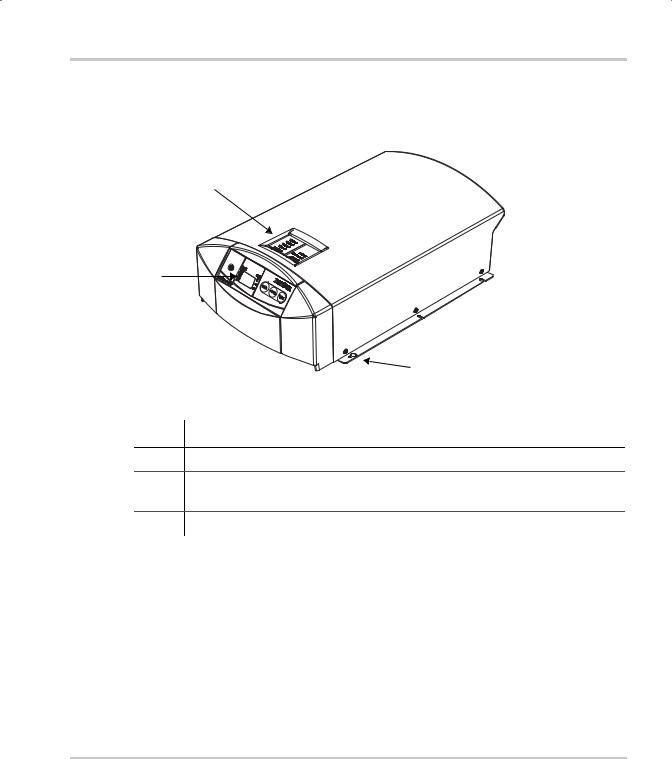
This section describes the parts of the XC Series. Figure 1-2 shows the XC Series.
2
1
3
Figure 1-1 XC Series
Item Description
1Remote display for all programming functions and monitoring of the XC Series.
2Onboard status panel for monitoring charger status and charging current at the XC Series when the remote display is mounted remotely from the charger.
3Mounting flanges
975-0187-01-01 |
1–3 |
Introduction
Information Centers of the XC Series
Remote Display
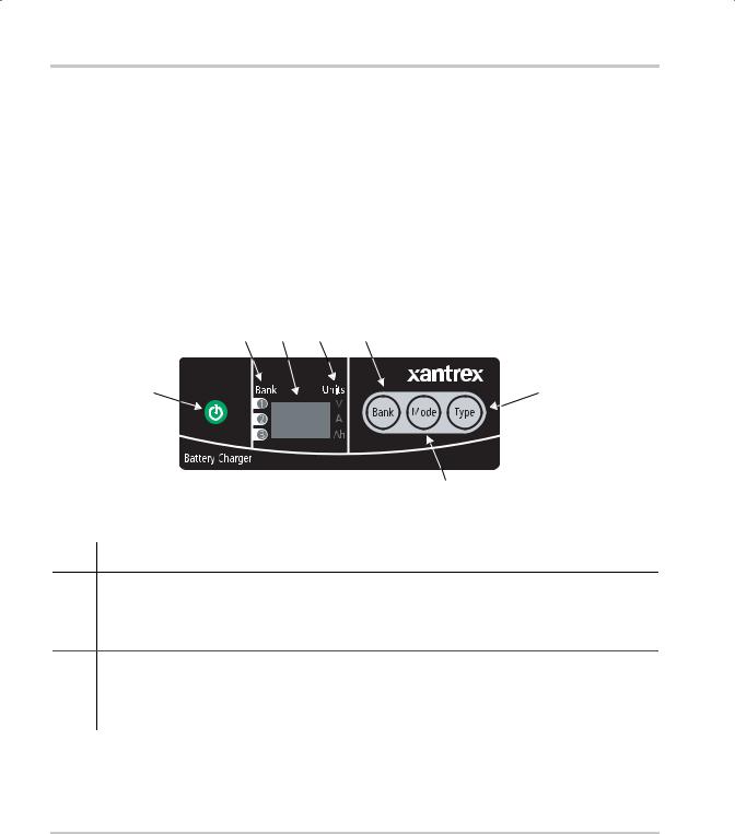
This section describes the parts of the remote display of the XC Series. The remote display can be rotated 180°, or it can be removed and remotely mounted up to 20 m (65 ft) from the XC Series for convenience. Figure 1-2 shows the remote display.
A “press and hold” action on the remote display means that the button must be held down for more than 2 seconds in order to send the instruction. A “press” action on the remote display means that the button must be pressed and released before 2 seconds have elapsed.
2 3 4 5
1 |
6 |
7
Figure 1-2 XC Series Remote Display
Item Description
1ON/STANDBY push button
•Press to turn on or disable the charger while AC power is connected
•Press and hold to apply selection when in setup or equalization mode
•Press to show battery bank voltages when AC is disconnected
2Battery bank indicator lights
•Illuminate to show which bank has been selected for setup or status display
•Illuminate during a fault or warning to show which bank has the fault or warning, or illuminate all three if the charger itself has the fault or warning
1–4 |
975-0187-01-01 |

Information Centers of the XC Series
Item Description
3Alpha-numeric display shows
•Configuration
•Fault or warning messages (see Table 4-2 on page 4–4)
•Battery bank voltage and current
•Type of charging (2 stage or 3 stage)
•State of charge
4Units indicator lights
•Illuminate to show unit of measure for the numeric read-out on the alpha-numeric display
5BANK selection push button
•Press to select a bank during setup
•Press at the same time as MODE to enter or exit equalization mode.
6TYPE selection push button
•Press to select flooded (lead acid), gel, AGM, or lead calcium batteries.
7MODE selection push button
•Press to select charging state during setup: 2 stage or 3 stage.
•Press at the same time as BANK to enter or exit equalization mode.
•Press and hold to enter setup.
The indicator lights and display are also used to indicate error codes. See Chapter 4, “Troubleshooting” for a list of faults and how to clear them.
975-0187-01-01 |
1–5 |
Introduction
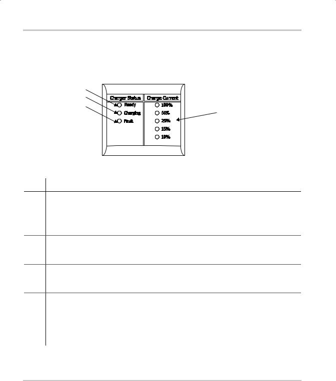
Onboard Status Panel
This section describes the parts of the onboard status panel of the XC Series. Figure 1-3 shows the panel.
2 3
4
1
Figure 1-3 XC Series Onboard Status Panel
Item Description
1Charge Current
•Displays the output charge current in % of charger maximum for the bank being charged
•100% indicator light flashes to indicate battery temperature too high (> 50 °C, 122 °F)
•10% indicator light flashes to indicate battery temperature too low (< 0 °C, 32 °F)
•25% indicator light flashes to indicate that a battery has been disqualified (see page 3–4)
2Charger Status - READY
•Ready indicator light illuminated indicates all batteries are fully charged, and are now in float or rest
3Charger Status - CHARGING
•Charging indicator light illuminated indicates unit is performing a normal charge cycle
•Charging indicator light flashing indicates that the unit is performing an equalization cycle
4Charger Status - FAULT
•Fault indicator light continuously illuminated indicates any fault condition that prevents the XC Series from charging one or more batteries, but is not a charger failure - remote display shows details of fault
•Fault indicator light flashing indicates the XC Series has experienced a charger failure - remote display shows err followed by CHf
1–6 |
975-0187-01-01 |
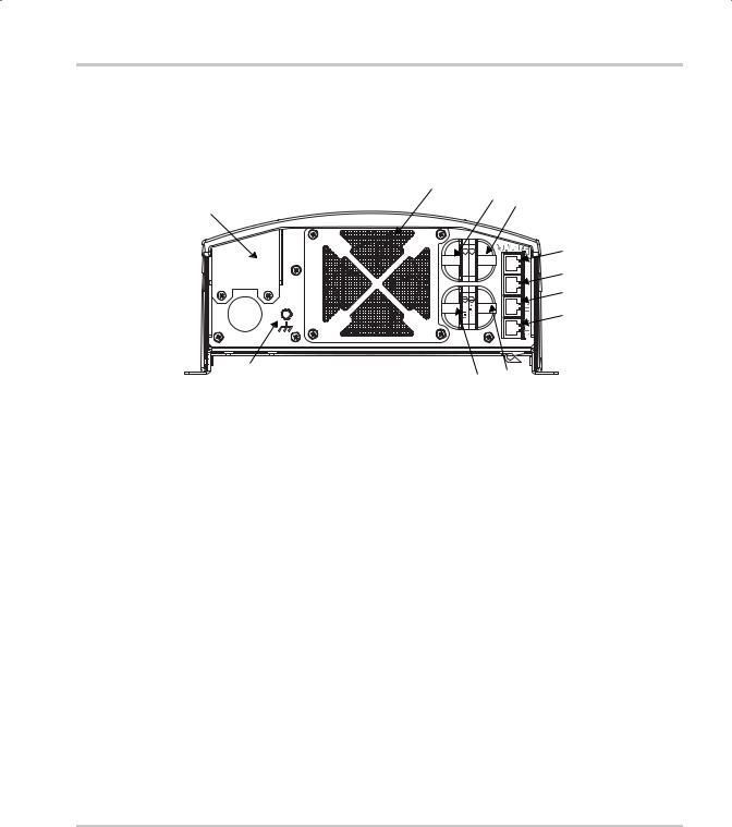
Rear Panel
Rear Panel
This section describes the parts of the rear panel of the XC Series. Figure 1-4 shows the rear panel.
9 7
8
11
+ +
2Bank 3Bank
10 |
6 |
5 |
|
|
Figure 1-4 XC Series Rear Panel
2
3
4
1
Item |
Description |
|
|
1 |
Remote display communication connector |
|
|
2 |
BTS1 (battery temperature sensor for bank 1) connector |
|
|
3 |
BTS2 (battery temperature sensor for bank 2) connector |
|
|
4 |
BTS3 (battery temperature sensor for bank 3) connector |
|
|
5 |
Battery negative, common for all 3 banks (6 mm stud) |
|
|
6 |
Battery positive for bank 1 (6 mm stud) |
|
|
7 |
Battery positive for bank 2 (6 mm stud) |
|
|
8 |
Battery positive for bank 3 (6 mm stud) |
|
|
9 |
Fan assembly |
|
|
10 |
Chassis ground (earth) for DC wiring |
|
|
11 |
AC wiring access panel |
|
|
975-0187-01-01 |
1–7 |
Introduction
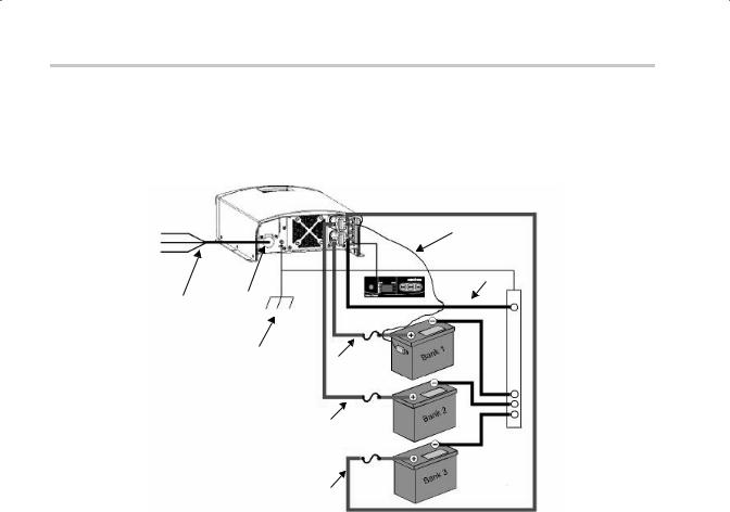
Preparing for Installation
The XC Series is designed to be permanently mounted. Figure 1-1 shows a typical installation with three batteries, a BTS and a remote display. It also shows the AC and DC wiring and protection devices required for a successful installation.
|
L |
|
|
|
|
9 |
|
|
|
N |
|
|
|
|
|
|
|
|
G |
|
|
|
8 |
|
|
|
|
|
|
|
|
|
|
|
|
|
|
|
|
|
|
|
3 |
|
|
|
1 |
2 |
|
|
|
|
|
|
|
|
|
|
|
|
||
|
|
|
|
10 |
5 |
6 |
7 |
|
|
|
|
|
4 |
|
|
|
|
|
|
|
|
|
|
|
|
|
|
|
|
|
|
5 |
6 |
|
|
|
|
|
|
|
4 |
|
|
|
|
|
|
|
|
|
|
|
|
|
|
|
|
|
5 |
6 |
|
|
|
|
|
|
|
4 |
|
|
|
|
Figure 1-5 XC Series System |
|
|
|
|
|||
1 |
|
AC mains source with correct size and type of circuit breaker |
||||||
|
||||||||
|
|
|
|
|
|
|
||
2 |
|
AC input wiring compartment |
|
|
|
|||
|
|
|
|
|
|
|
|
|
3 |
|
DC negative cable |
|
|
|
|
||
|
|
|
|
|
|
|
|
|
4 |
|
DC positive cables |
|
|
|
|
||
|
|
|
|
|
|
|
||
5 |
|
DC circuit breaker or DC fuse and disconnect |
|
|
|
|||
|
|
|
|
|
|
|
|
|
6 |
|
Battery or battery bank |
|
|
|
|
||
|
|
|
|
|
|
|
||
7 |
|
Engine ground bus or DC negative bus |
|
|
|
|||
|
|
|
|
|
|
|
|
|
8 |
|
Remote display panel |
|
|
|
|
||
|
|
|
|
|
||||
9 |
|
Battery temperature sensor (#1 is standard equipment. #2 and #3 are optional) |
||||||
|
|
|
|
|
|
|
|
|
10 |
|
DC chassis ground (earth) |
|
|
|
|
||
|
|
|
|
|
|
|
|
|
|
|
|
|
|
|
|
|
|
1–8 |
|
|
|
|
|
975-0187-01-01 |
||
Preparing for Installation
Tools and Materials
To mount and connect the XC Series you need the following tools:
•10 mm wrench or socket for the DC terminals and ground stud
•Phillips screwdriver for securing the AC wiring compartment cover
•power drill
•drill bit for pilot holes for mounting screws
•wire stripper
•manufacturer's recommended crimp tool for any crimp terminals that are being used
You need the following materials:
•3 conductor AC input wiring
Use the information in “AC Wiring” on page 1–13 and your local electrical codes to determine the correct wire and breaker or fuse.
•AC cable strain relief (if the one included is not sufficient for your local electrical code requirements)
•appropriately sized DC cables for each battery, with suitable connectors at the battery end
•appropriately sized DC chassis ground (earth) with suitable connectors
•ring terminals to fit 6 mm (1/4 in.) studs at the charger end
•DC fuse and disconnect or circuit breaker for each battery bank
•mounting hardware, 3 mm (#6) corrosion resistant 6 pieces.
•other means to route and secure AC and DC wiring
975-0187-01-01 |
1–9 |

Introduction
Location
Install the XC Series in a location that meets the following requirements:
Condition |
Requirement |
|
|
Dry |
The XC Series must be installed in a dry location not subject to rain, spray or splashing |
|
bilge water. |
|
|
Clean |
The XC Series should not be exposed to metal filings or any other form of conductive |
|
contamination. |
|
|
Cool |
The ambient air temperature should be between 0 °C - 50 °C (32 °F - 122 °F) for best |
|
performance. |
|
|
Ventilated |
There must be at least 76 mm (3 in.) of clearance on each end of the XC Series for air |
|
flow. Ventilation openings on the unit must not be obstructed. If mounting in a tight |
|
fitting compartment, the compartment must be ventilated with cut-outs to prevent |
|
overheating. |
|
|
Safe |
This battery charger is ignition protected, so it can be installed in areas containing |
|
gasoline tanks or fittings which usually require ignition protected equipment. Xantrex |
|
recommends, however, that it is safest not to install electrical equipment in these areas. |
|
|
Close to |
The XC Series should be installed as close as possible to the batteries, but not in the |
batteries |
same compartment to prevent excess corrosion. Avoid excessive cable lengths and use |
|
the recommended wire sizes. Xantrex recommends <3% wire voltage drop (round |
|
circuit) on battery cables under full load. |
|
|
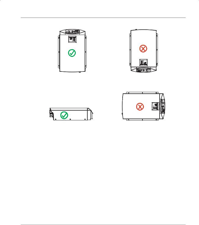
When planning where and how to mount the XC Series, be sure the installation allows the charger to be mounted in one of the permitted vertical or horizontal orientations.
For marine installations, only the mounting configurations with a check mark in Figure 1-6 meet the North American and European marine requirements. Marine products are required to meet drip tests, to ensure safety in the presence of condensation. If you are certain your installation is not subject to moisture, configuration d) in Figure 1-6 may be used.
1–10 |
975-0187-01-01 |
Preparing for Installation
a) |
b) |
Vertical |
Vertical - this configuration is unsafe and |
|
should not be used |
c) |
d) |
|
|
Vertical - this configuration may be used |
|
|
|
|
|
|
Horizontal |
||
|
|
in an environment which is dry and clean |
|
|
only (non-marine) |
Figure 1-6 XC Series Mounting Orientations
975-0187-01-01 |
1–11 |
Introduction
Wiring Requirements
WARNING
Wire and fuse sizes are dictated by electrical standards. Different standards apply in different countries and different types of installations, for example, boat, home or RV. It is the responsibility of the installer to ensure that the installation complies with all applicable standards.
CAUTION
Ensure that both wires and fuses are correctly sized.
Maximum continuous current available from the charger may be an additional 6–10% above the nominal current rating of the charger. Output current may also vary depending on ambient temperature conditions.
DC Wiring
The following two tables show some typical wire sizes, based on 3% voltage drop (round circuit), 75 °C (167 °F) rated wire and wiring being inside the engine compartment – assumed ambient of 50 °C (122 °F).
Table 1-1 DC Wiring Requirements
Wire Length |
|
|
|
|
|
(maximum length one way) |
Wire Size (AWG and mm2) |
|
|
||
|
|
|
|
|
|
feet |
meters |
XC3012 |
XC5012 |
XC2524 |
XC1524 |
|
|
|
|
|
|
5 |
1.5 |
No. 10 |
No. 6 |
No. 10 |
No. 12 |
|
|
5 mm2 |
13 mm2 |
5 mm2 |
3 mm2 |
7.5 |
2.25 |
No. 8 |
No. 6 |
No. 10 |
No. 12 |
|
|
8 mm2 |
13 mm2 |
5 mm2 |
3 mm2 |
20 |
6 |
No. 6 |
No. 4 |
No. 10 |
No. 12 |
|
|
13 mm2 |
19 mm2 |
5 mm2 |
3 mm2 |
|
|
|
|
|
|
1–12 |
975-0187-01-01 |
 Loading...