


I4.35 |
Link 2000
Owner's Manual
OWNERS MANUAL
Xantrex
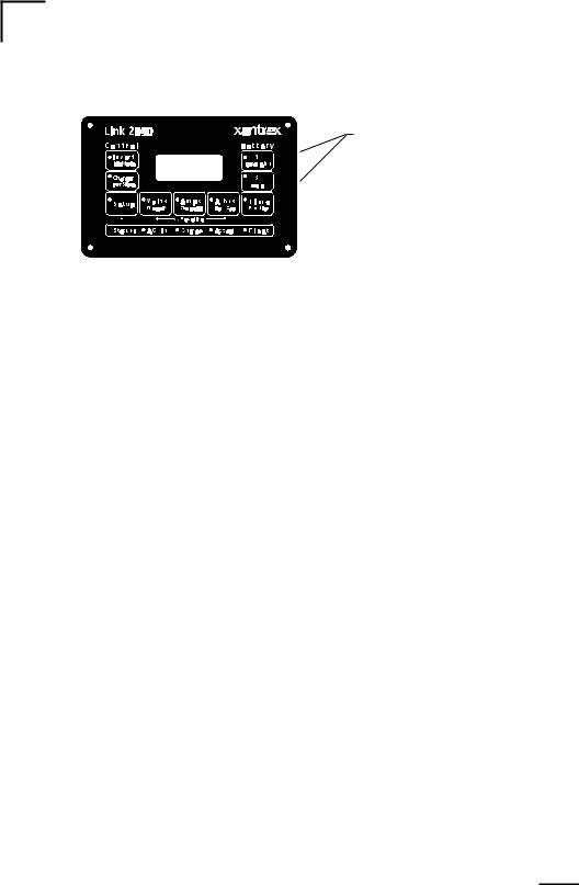
Link 2000
Inverter Controller
and Dual Battery Monitor

TABLE OF CONTENTS
One Page Summary of Features |
Center |
Introduction and Special Notes |
3 |
Monitor Functions |
4–5 |
Inverter and Charger Functions |
5 |
Status Line and Starting and Stopping Equalize |
6 |
Setup |
7 |
Inverter Setup |
8 |
Monitor Setup |
9 |
Functions Setup |
10–14 |
Data Mode |
15 |
How to Use The Link 2000 Control Panel |
16–17 |
Ideal Charge Curve |
18 |
Synchronizing to a Full Battery (Resetting Amp Hours to Zero) |
20 |
Rules for Changing the Charged Parameters |
21 |
Selection Rules |
22 |
Reset / Info Functions |
23 |
High Discharge Rates and Peukert's Equation |
24–25 |
Typical Peukert's Exponents |
26–27 |
Error Codes and Troubleshooting |
28–29 |
Microprocessor Reset Procedure (Resetting to Factor Defaults) |
30–31 |
Setup and Historical Data Summary |
32 |
Warranty |
33 |
Required Reading Prior to Installation |
36 |
Wire By Wire Instructions |
37 |
Specifications |
39 |
INSTALLERS:THISDOCUMENTISIMPORTANTFOR OPERATION—PLEASE LEAVE IT WITH THE OWNER.
THIS MANUAL APPLIES TO LINK 2000 METERS WITH SERIAL NUMBERS ABOVE 8500
AND LINK 2000-R METERS WITH SERIAL NUMBER ABOVE 5000
Notice of Copyright
Xantrex Link 2000 Inverter Controller and Dual Battery Monitor © October 2002 Xantrex International. All rights reserved.
Disclaimer
UNLESS SPECIFICALLY AGREED TO IN WRITING, XANTREX TECHNOLOGY INC. (“XANTREX”)
(a)MAKES NO WARRANTY AS TO THE ACCURACY, SUFFICIENCY OR SUITABILITY OF ANY TECHNICAL OR OTHER INFORMATION PROVIDED IN ITS MANUALS OR OTHER DOCUMENTATION.
(b)ASSUMES NO RESPONSIBILITY OR LIABILITY FOR LOSS OR DAMAGE, WHETHER DIRECT, INDIRECT, CONSEQUENTIAL OR INCIDENTAL, WHICH MIGHT ARISE OUT OF THE USE OF SUCH INFORMATION. THE USE OF ANY SUCH INFORMATION WILL BE ENTIRELY AT THE USER’S RISK.
Date and Revision: October 2002, Revision 1 |
Part Number: 445-0198-01-01 |
|
Contact Information Web: www.xantrex.com |
Email: CustomerService@xantrex.com |
|
Phone:1800 670 0707 (tollfreeinNorthAmerica)1604422-2777(direct) |
Fax:1604420-2145 |
|
2

INTRODUCTION AND SPECIAL NOTES
The LINK 2000 is an integrated battery monitor and inverter/charger control. It displays the critical information necessary for 12 V or 24 VDC system battery management and allowsprecisecontrolofcriticalinverterandchargerfeatures.TheLink2000-Rcomeswith an additional manual describing the Ideal Regulator option. The LINK 2000 may be used as a stand-alone battery monitor or with the following inverter/chargers:
FREEDOM 10, 15, 20, 25, and 30
In order to understand, use, and install the LINK 2000, PLEASE read this manual! It is as short as possible and provides important information. For installation, operation, or warranty questions, please call Xantrex.
The following Important Special Notes contain cautions and special considerations that mustbeconsideredduringtheinstallationoftheLINK2000.Failuretoreadandfollowthese specialnotescanleadtodamageoftheLINK2000,theinverter,orotherelectricalequipment.
 The Helping Hand is used to draw your attention to very important sections of this manualortoindicateitemsthatmayneedtobechangedthroughtheSETUProutine.Please take the time to read these sections.
1)DO NOT DISCONNECT THE NEGATIVE BATTERY CABLE TO THE FREEDOM WITH THE INVERTER OR CHARGER TURNED ON! WHEN INSTALLING, CONNECT THE INVERTER CABLES BEFORE PLUGGING THE REMOTE CABLE INTO THE LINK 2000. UNPLUG THE REMOTE CABLE BEFORE THE FREEDOM INVERTER IS DISCONNECTED FROM THE BATTERY.
2)Turn the ON/OFF switch located on the inverter to the OFF position.
3)When used in a mixed voltage (12 V and 24 V) system, Battery #1 is the battery that the LINK2000usesforvoltageregulation.Makesureitisthebatterythatisusedbytheinverter/ charger, or with the alternator regulator option it must be the battery being charged by the alternator. See Functions Mode F11 on page 13.
BASIC BATTERY FACTS
1)One amp-hour (Ah) is 1 amp for one hour, or 2 amps for 1/2 hour, or 4 amps for 1/4 hour, and so on.
2)A liquid battery is generally considered completely discharged when the battery voltage reaches 10.5 volts for a 12 volt battery.
3)Batteries for cycling service are normally rated with a) a 20-hour discharge rate which means, for example, a 100 Ah battery will sustain 5 amps for 20 hours, and b) a reserve capacity stated in minutes for a 25-amp discharge rate.
4)OurMid-CapacityRulesaysthatdischargebelow50% shortensbatterylife andcharging morethan85%takestoolongwith anengine-drivenchargingsystem.So,35%of thebattery capacity is all that is normally available.
3
MONITORFUNCTIONS
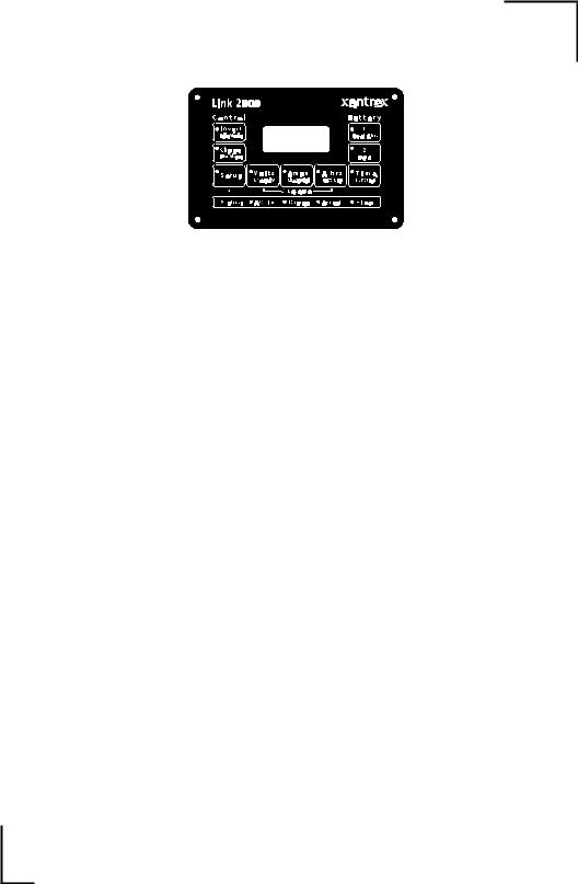
Please also refer to the one-page summary of features in center of this manual. The small blue legends indicate Setup functions described later.
BATTERYSELECT
The battery to be monitored is selected by pressing the #1 or #2 switch. A Green LED indicates which battery is selected. ("Battery" may be a "bank" of batteries.)
VOLTS
When the VOLTS switch is pressed, the voltage of the selected battery is displayed. The measurement range is from 8.5 V to 50 V. The resolution is 0.05 volts. See page 39 for power supply specification.
AMPS
When the AMPS switch is pressed, the current flowing into or out of the selected battery is displayed. Amps being consumed are displayed as a negative number. Charging amps are displayed as a positive number (no sign). The resolution below 42 amps is 0.1 amps. Above 42 amps the resolution is 1 amp. The range is from -500 A to 500 A. Overrange is indicated by OL.
Ahrs
When the A hrs switch is pressed, the amp hours (Ah) consumed from the battery is displayed as a negative number. During discharge the negative number will grow as amp hours are consumed and the meter counts down. During charging, the number of amp hours consumed will decrease as the meter counts back up toward zero. The range is + 9,999Ah.
If the battery continues to be charged after the meter counts back up to zero, overcharge amp hours are accumulated and displayed as a positive number. If there is an accumulated positive number in the display when discharging begins, the meter automatically resets to zero and begins counting down. See Overcharge Amp Hours on page 16.
The meter also automatically resets to zero after a discharge/charge cycle that satisfies the conditions for a recalculation of the Charge Efficiency Factor (CEF). In other words, if the battery is discharged 10% and then recharged until the charged parameters have been met, the amp hours consumed display is reset to zero.
TIME
When the TIME switch is pressed, the time which the load can continue to be run is displayed. The display is in hours with 0.1 hours resolution. The unit may be set up to calculate the time remaining based on the instantaneous current, or a rolling average of the last 4, 16, or 32 minutes. The time remaining function also takes into account the magnitude of the discharge current (see pages 24–27). The maximum time remaining is 255 hours. If you see this display, it means that the current being consumed could be supplied for more than 255 hours. During charging, current is a positive (unsigned) number and the
4
Time remaining display reads C C C.
 For the TIME function to operate correctly you must enter your BATTERY CAPACITY through the SETUP routine (see page 9). You must also set up the correct PEUKERT'S EXPONENT (see page 13). It is also affected by your selection of DISCHARGE FLOOR (see page 14).
Caution: The TIME display is an estimate of how long your battery can sustain a load. Wild variations in battery current, battery condition, erroneously declared battery capacity, Peukert's exponent, temperature, or discharge floor, and prior charge and discharge history may affect the accuracy of this estimate. Please use this display only as a guide. The LINK 2000 provides you with several important battery parameters. Using all of them, including voltage, current, amp hours consumed, and time remaining, allows you to know about the state-of-charge of your battery. Do not rely on a single value to determine battery status or performance.
LO BAT
When 50% of the declared capacity of either Battery #1 or #2 is consumed, LO BAT flashes in the upper left hand corner of the display. (This indicator is affected by both the declared battery capacity and the discharge floor setting.)
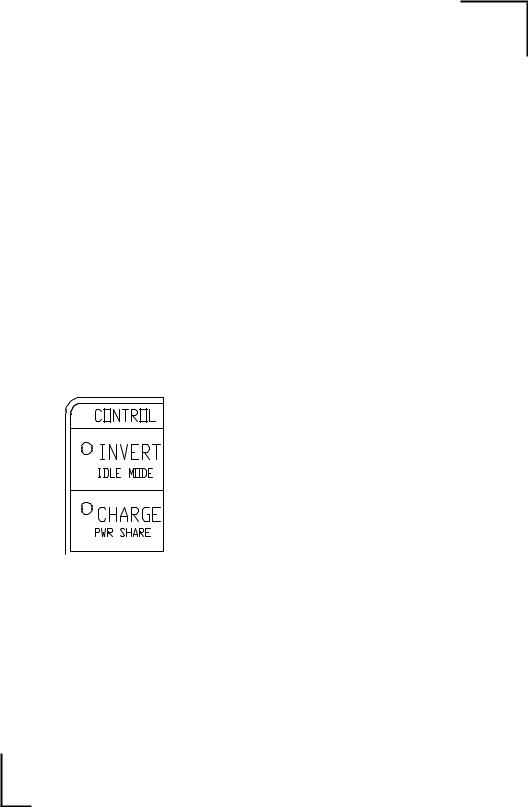
INVERTER/CHARGERFUNCTIONS
INVERT
When the INVERT switch is pressed, the inverter is enabledandtheGreenLEDislit.Theinverterwillonlyprovide output if it is hooked up to the battery and there is no external AC power available. The inverter ON indicator does not indicateactualoperation,onlythattheinverterisenabled.The initial power-up condition is with the inverter turned OFF.
CHARGE
When the CHARGE switch is pressed, the charging function of the Freedom Inverter/Charger is enabled. The GreenLEDislitwhenthechargerisenabled.Theinitialpowerupconditioniswiththechargerenabled.Thechargerwillonly provide output if it is hooked up to a battery and an external source of AC power is present (shorepower or generator).
MARINE AND RV OPERATING TIP
When utility power is available, any loads normally supplied by the inverter are automatically transferred to utility power through the internal transfer switch. When utility power is not available the loads run on stored energy in the battery. If you have a load such as an electric space heater running on a circuit that is automatically transferred, you run the risk of deeply discharging your battery if there is a utility blackout. To avoid this, turn the inverterfunctionOFFwhenleavingtheboatorRVunattended.Leavingthechargerfunction ON will ensure a full battery when you return.
5
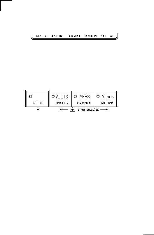
STATUS LINE
There are four LED status indicators to show the presence of AC power and the charger's cycle state.
AC IN: Green LED on when AC is present. CHARGE: Red LED on when charger is in Charge mode.
Flashes Red when charger is in Equalize mode. ACCEPT: Orange LED on when charger is in Acceptance mode. FLOAT: Green LED on when charger is in Float mode.
STARTING AND STOPPING EQUALIZE
The Equalize Cycle conditions the battery with a controlled overcharge to remove Lead Sulfate that is not removed during normal charging. Liquid batteries should be Equalized every 30 days when in cycling service.
CAUTION! Turn off voltage sensitive DC loads before equalizing battery!
DC Voltage from the charger may go to 17 VDC (34 V for 24 V system) during equalizing !
Charge batteries fully before equalizing. To start the Equalize Cycle, first be sure that the Charger is ON, then press the SETUP BUTTON for five seconds until the LED begins to flash. Now press both the VOLTS and the A hrs BUTTONS simultaneously. Hold them both down for five seconds, until the Red CHARGE LED begins to flash, and the "E" in the display goes away.
To terminate the Equalize Cycle and force the charger into the Float mode, repeat the same procedure as above. The cycle automatically terminates after eight hours, or if AC power is interrupted.
 Equalizing causes the battery to gas. You should check your battery electrolyte before and after equalization. Do not overfill before equalization as the electrolyte may expand enough to cause it to flow over the tops. You should be present during this type of charging. Make sure there is adequate ventilation. Leave the filler caps on or cover the tops with a folded paper towel. Terminate the cycle if a battery starts to overflow or overheat.
Gelled batteries are not normally equalized. However, if they have been severely discharged, it may be the only way to get them to begin to accept a charge. The voltage is limited to the Accept charging level but the cycle lasts for 8 hours. Be sure that the battery TYPE # is set to #1 or #2 before using this cycle on gelled batteries (or #3 for AGM type batteries).
Note: Equalizing voltages for Type #1, #2, and #3 batteries is limited to the acceptance voltage for the respective battery type.
6
SETUP
I 4 . 3 5
 The LINK 2000 has been set up with default values chosen to work with a typical system. Normally the only values that must be changed are:
1) |
Battery capacity (page 9) |
3) Battery type (liquid or gel) (F02 page 11). |
2) |
Ambient Temperature (F03 page 11) |
4) Peukert's exponent (F08 page 13). |
The SETUP BUTTON is used to access the functions in small blue text below each button's primary function. It is also used for certain advanced functions described later. To set up a value or function:
1)Select the battery to be set up by pressing Battery #1 or #2, (or Invert, or Charge, when setting up Idle Mode or Pwr Share).
2)Hold down the SETUP BUTTON until the green LED flashes at one-second intervals.
3)Release the SETUP BUTTON and press and hold the function to be set up. The LED ofthefunctionbeingsetupwillalsobegintoflashatone-secondintervals.Thepresentvalue of the function will appear in the display.
4)After three seconds, with the button pressed, the display will begin scrolling. When the desired value appears, release the button. If you continue to hold down the button, the display will increment to the end of its range, roll over to its minimum value, and continue to scroll. You may also "bump" a value by repeatedly pressing the button.
Youmay setupadditional values,orfunctions, aslong asthe SETUPLEDcontinues toflash.WhentheSETUPLEDstopsflashing,allvaluesthatwerechangedduringthesetup routine will be stored in nonvolatile memory.
SUMMARY OF FACTORY DEFAULT VALUES
INVERTER/CHARGER CONTROL
Standby |
= 4 watts (5 watts in Series 458 units) |
Power Sharing |
= 30 amps ("OFF" for Freedom 25) |
MONITORING FUNCTIONS |
|
Charged Voltage |
= 13.2 volts for 12 volt systems |
|
= 26.4 volts for 24 volt systems |
Charged Current % = 2% (of battery capacity) |
|
Battery Capacity |
= 200 Ah |
CEF (Charge Efficiency Factor)= 87% for Liquid Acid |
|
|
= 90% for other cell types |
Ambient Temp. |
= 70 °F |
Type |
= #0 Liquid |
Peukert's Exponent= 1.25
7

INVERTER SETUP
IDLE MODE: The default value is 4 watts. This means it takes a 4-watt AC load to turn the inverter on from its low power idle mode. Setting a value of 0 watts means the inverter is always on. The low power idle current is about 0.25 amps. When idle mode is set to 0 W the current consumption goes up to about 0.9 amps. Range = 0 W, 4 W, 6 W, 15 W. (0–15 watts in 5-watt steps in Series 458 units.)
SETUP EXAMPLE: To set the IDLE MODE to 0 watts, first select the INVERT on, then press the SETUP BUTTON until the Green LED begins to flash. Now, press and hold the IDLE MODE BUTTON. The present value will appear. The display will scroll afterthreeseconds.Holdthebuttondownuntil0appears.Releasethebutton.Thenewvalue will remain in the display for about five seconds. When the display reverts to the normal monitoring function the new value is stored in nonvolatile memory. To see if the new value has been successfully stored, repeat the setup procedure but do not scroll to a new value.
PWR SHARE: The default value is 30 amps (or OFF for Freedom 25). The power sharing feature automatically reduces the charger output, and therefore the AC power consumption, if the load passing through the inverter's automatic transfer switch exceeds the setup value. This load management feature helps prevent AC supply breakers from tripping when boats or RVs are plugged into AC power and the charger, water heater, and perhaps other loads all come on at once. In "Off Grid" applications the auxiliary generator often has several jobs—water pumping, running the washing machine, or heavy power tools—in addition to supplemental battery charging. With Power Sharing, when a heavy load turns on, it reduces charger output to help supply the heavy load. The ranges below are for units with serial numbers greater than 100,000:
Freedom 10, 15 & 20 Range = 5, 15, 20, 30 A; Freedom 25 & 30 Range = 5, 20, 30 A, OFF; Freedom 10E & 20E Range = 2, 5, 10, 15 A; Freedom 25E Range = 2, 10, 15 A, OFF
For Freedom serial numbers below 100,000 use this table to interpret the display.
Model |
F10 |
F10 |
F10E |
F10E |
F20 |
F20 |
F25 |
F25 |
Serial# |
<70759 |
>70760 |
<71746 |
>71747 |
<70699 |
>70700 |
<70801 |
>70802 |
Display |
Amps |
Amps |
Amps |
Amps |
Amps |
Amps |
Amps |
Amps |
0 |
30 |
30 |
15 |
15 |
30 |
30 |
OFF |
OFF |
1 |
20 |
20 |
10 |
10 |
20 |
20 |
50 |
30 |
2 |
15 |
15 |
7.5 |
7.5 |
15 |
15 |
30 |
20 |
3 |
10 |
5 |
5 |
2 |
10 |
5 |
20 |
5 |
For Series 458 units, the range is 0–50 amps, settable in 5-amp steps.
ANOTHER SETUP EXAMPLE: To set PWR SHARE to 20 amps on a F10 Model with a serial number below 100,000, first select the CHARGE on, then press the SETUP BUTTON until the green LED begins to flash. Now, press and hold the PWR SHARE BUTTON. The present value will appear. The display will scroll after three seconds. Hold the button down until 1 appears (see table above). Release the button. The new value will remain in the display for about 5 seconds. When the display reverts to the normal monitoring function the new value is stored in nonvolatile memory.
8

MONITORSETUP
Normally the only MONITOR SETUP parameter that must be changed is BATT CAP (see bottom of this page). Please read the section on selecting charged parameters (page 21–22) before changing CHARGED V or CHARGED % default values. (See FUNC SETUP on page 10 for other system values that may need to be changed.)
Setting the following parameters only affects the operation of the monitor, meaning that changing the Charged V parameter does not change the voltage set point of the charger in the FREEDOM Inverter/Charger. It only sets the point at which the monitor considers the battery full. To change the charging voltage during the Acceptance and Float cycles use Ambient Temp. Setup routine. Note also that when the FREEDOM is the charging source, the Charged % is always 2%.
SELECT BATTERY #1 OR #2: To set up a battery parameter, press the button for the battery you wish to set up. The LED will light. Do this first as setup changes are only made to the selected battery.
CHARGED V: The ability to set up a Charged Voltage above which the monitor considers the battery full allows it to be used with any charging system or battery chemistry. The default Charged Voltage is 13.2 volts for 12-volt systems and 26.4 volts for 24volt systems. The LINK 2000 automatically selects the correct value based on the voltage it senses. (If the Alternative Energy function F05 is ON, the default value is 13.5 volts or 27.0 volts. See FUNCTIONS SETUP, page 10, for details.)
To change CHARGED V follow the same procedure as described previously: Select the battery to be set up. Press SETUP until the LED begins to flash. Then release the button, and press CHARGED V until the desired voltage appears and then release the button. The new charged voltage is stored in nonvolatile memory. If the charged voltage is inappropriate for the sensed battery voltage, Error E14 is displayed (see Error Codes and Troubleshooting, pages 28–29). Be sure to read the section on selecting correct charged parameters (pages 21–22) before changing the charged voltage.
CHARGED %: The default value is 2%. This means that the charging current (amps) flowing into the battery must fall below 2% of the declared battery capacity before the meter considers the battery full. For example, using the default values of 2% and 200 Ah means the current must fall below: 4 amps = 2% x 200 Ah.
Before changing the CHARGED % from either of these values, be absolutely sure you understand the section on selecting charged parameters (page 21–22). Setup and storage to nonvolatile memory is the same as for the function above.
 BATT CAP: The default value is 200 Ah. The battery capacity must be set up if it varies significantly (10–20%) from the default. The battery capacity is used in the calculation to determine when the battery is full and in the TIME remaining function.
To change the battery capacity, press SETUP until the LED begins to flash, then release the button. Now press BATT CAP. Scroll until the desired battery capacity is in the display. If you are unsure of your battery capacity you may first test it as described on page 17. The battery capacity is stored in nonvolatile memory. If you change to a different capacity battery you must change this number. Range = 20–2000 Ah in 20 Ah increments.
9
FUNCTIONS SETUP
FUNC: The FUNC (Function) mode is used to set up special functions or features that are not commonly changed. They might be thought of as internal software switches that allow the selection of special functions, or values that, once set, are seldom changed.
 Normally the only functions that must be changed are F02 Battery Type, F03 Ambient Battery Temperature, and F08 Peukert's Exponent. (See page 9 for how to set battery capacity.)
The setup process for functions is slightly different because the FUNC button is used first to scroll to the function to be set up, and then to scroll through the values for that function. To access the FUNC mode:
1)Press and hold the SETUP button until the green LED begins to slowly flash, then release the button.
2)Now press the (blue) FUNC button. The letters F01 will appear in the display and the FUNC LED will begin flashing, indicating you are in the FUNC mode.
3)Scroll to the function to be set up by holding down the FUNC button.
4)Release the FUNC button and wait for the current value of the function you have selected to appear in the display. This will take about three seconds.
5)Press the FUNC button now and the display will scroll through the range of values. Stop scrolling when the value you wish appears in the display.
6)If you wish to continue to set up other functions, press the SETUP button until the green LED by the FUNC button stops flashing. You may now choose any blue key to continue setting up the LINK 2000. If you press the FUNC button again the process will begin at the next function after the one you last set up. Whatever functions you have set up will become active when the display reverts to its normal mode.
FUNCTIONS TABLE
F01 - AVERAGE PERIOD FOR TIME REMAINING CALCULATION
0 = INSTANTANEOUS (DEFAULT)
1 = 4-MINUTE AVERAGE
2 = 16-MINUTE AVERAGE
3 = 32-MINUTE AVERAGE
There are four averaging periods that the LINK 2000 can use to calculate the time of operation remaining. You may select present consumption level (instantaneous), a four-minute rolling average, a 16-minute, or a 32-minute rolling average. Which method is best for you depends on your installation. Most installations will find the instantaneous or the four-minute average appropriate.
Operating Tip: Use the longest period of time you can to ensure long term load variations are considered. If you want instant feedback, use the instantaneous display (no averaging) "0" display.
10
F02 - BATTERY TYPE |
|
0 = LIQUID CELL (DEFAULT) |
1 = GEL CELL (STANDARD) |
2 = GEL CELL (FAST CHARGE) |
3 = AGM (Absorbed Glass Mat) |
This function (Default: Type 0, standard liquid cells) sets the appropriate charge and float voltages for the FREEDOM charger (see table below) and sets an appropriate Peukert exponent. Gel cell owners may use Type 1 or Type 2, but should consult with the battery manufacturer prior to using the more aggressive charging regimen described by Type 2. Type 3 sets Acceptance and Float voltages suited to AGM type batteries.
 F03 - VIEW OR SET AMBIENT BATTERY TEMPERATURE
THIS FUNCTION DEPENDS ON THE SETTING OF F14 (SEE PAGE 14)
IF F14 IS ON, F03 VIEWS THE PRESENT BATTERY TEMP. (°F)
If F14 is ON, charging voltage of the Freedom charger and the Ideal Regulator (if using a Link 2000-R) is based on the TEMPERATURE COMPENSATION TABLE below. The temperature is displayed until another button is pressed on the Link.
IF F14 IS OFF, F03 SETS A DECLARED BATTERY TEMP. (°F)
DEFAULT = 70 °F |
RANGE = 30–120 °F |
STEP = 10 °F |
The default value for ambient temperature is 70 °F. The ambient temperature of the battery may be set up to select the appropriate Charge and Float Voltages for the charger. The temperature may be selected in 10 °F increments. The setup procedure is the same as previously described.
Setting up a different value should only be done if the battery is at a temperature significantly different from 70 °F when they are being charged from the FREEDOM. If the batteries are located in a hot engine room, but are not normally charged from the FREEDOM when the engine is running, do not adjust the temperature to the engine room level. High temperatures are destructive to batteries. If your batteries are regularly subjected to temperatures above 100 °F you should relocate them or supply forced fresh air ventilation.
 Caution! Do not adjust to extremes unless the battery is normally at that temperature. Destructive overor under-charging may occur. Multiply values by 2 for 24-volt systems. Voltages are typical, charger regulation + 0.2 volts DC.
|
|
TEMPERATURE COMPENSATION TABLE |
|
|
||||||
TEMP |
TYPE 0 |
TYPE 1 |
TYPE 2 |
TYPE 3 |
||||||
|
|
Liquid |
Gel 1 (Std) |
Gel 2 (Fast) |
AGM |
|
||||
°F |
°C |
ACCEPT |
FLOAT |
ACCEPT FLOAT |
ACCEPT |
FLOAT |
|
ACCEPT |
FLOAT |
|
120 |
49 |
12.5 |
12.5 |
13.0 |
13.0 |
13.0 |
13.0 |
|
12.9 |
12.9 |
110 |
43 |
13.6 |
12.7 |
13.5 |
13.0 |
14.0 |
13.4 |
|
13.9 |
12.9 |
100 |
38 |
13.8 |
12.9 |
13.7 |
13.2 |
14.1 |
13.5 |
|
14.0 |
13.0 |
90 |
32 |
14.0 |
13.1 |
13.8 |
13.3 |
14.2 |
13.6 |
|
14.1 |
13.1 |
80 |
27 |
14.2 |
13.3 |
14.0 |
13.5 |
14.3 |
13.7 |
|
14.2 |
13.2 |
70 |
21 |
14.4 |
13.5 |
14.1 |
13.6 |
14.4 |
13.8 |
|
14.3 |
13.3 |
60 |
16 |
14.6 |
13.7 |
14.3 |
13.8 |
14.5 |
13.9 |
|
14.4 |
13.4 |
50 |
10 |
14.8 |
13.9 |
14.4 |
13.9 |
14.6 |
14.0 |
|
14.5 |
13.5 |
40 |
5 |
15.0 |
14.1 |
14.6 |
14.1 |
14.7 |
14.1 |
|
14.6 |
13.6 |
30 |
-1 |
15.2 |
14.3 |
14.7 |
14.2 |
14.8 |
14.2 |
|
14.7 |
13.7 |
11

Freedom units produced prior to serial #100,000 have temperature compensation only for warm or cool environments. The temperature setup sets the voltages as per below:
TEMP |
TYPE 0 (Liquid) |
TYPE 1 (Gel 1) |
||||
|
Accept |
Float |
Equalize |
Accept |
Float |
Equalize |
Above 80 °F |
13.9 |
13.3 |
15.8 |
14.1 |
13.8 |
14.1 |
Below 80 °F |
14.4 |
13.5 |
16.3 |
14.4 |
13.8 |
14.4 |
F04 - TOGGLE DISPLAY BETWEEN AHR AND KWHR DEFAULT OFF = Ah DISPLAY MODE
ON = Ah/kWh ALTERNATING DISPLAY MODE
When this function is selected theAhrs display alternates between the normal amphour mode and the kilowatt-hour counter that the LINK 2000 uses to determine if 100% of the energy consumed from the battery has been returned. A recalculation of the CEF is notpermittedunlessthiscounterisgreaterthan0.00kWh.Thiscountercountsdownduring discharge and the kilowatt hours consumed are displayed with a negative number. During charging it counts back up with 100% efficiency. Not allowing a recalculation of the CEF and an Ah reset until a positive number is in the counter ensures that there will not be a premature reset. See page 21 for conditions required for a recalculation of the CEF and an Ah reset.
F05 - ALTERNATIVE ENERGY MODE DEFAULT: OFF
ON = USE ALTERNATIVE ENERGY DEFAULTS
Turn this mode on if your Link 2000 is used in Alternative Energy Systems. This function 1) reduces the time necessary to satisfy the charged parameters from five minutes to one minute; 2) sets Batt #2 discharge floor to 100%; 3) prevents Batt #2 from doing Ah resets; 4) changes Charged V parameter to 13.5 V (27 V). If you're using a semimechanical photovoltaic controller, we strongly suggest you also consider changing Charged Current to 4%.
F06 - MANUALLY SET CEF (NOT RECOMMENDED) DEFAULT OFF = AUTO RECALCULATION OF CEF DISPLAY = A87 OR A90 (DEPENDS ON BATTERY TYPE) RANGE = 65–99 STEP = 1
Allows manual set up of CEF (Charge Efficiency Factor). Default display A87 or A90 (depending on battery type selected—see F02) indicates automatic CEF recalculation feature. Returning to A87 or A90 from a user CEF restores the automatic CEF feature. If a user-setup CEF has been selected it will appear as a U## ( U preceding a number) in the DATA mode—see page 15. A different CEF may be set up for each battery; only the selected battery's CEF will be changed.
F07 - SET TEMPERATURE COEFFICIENT
DEFAULT = 0.5 RANGE = 0.1–0.9 STEP = 0.1
This factor compensates for capacity change with temperature. Typical value 0.5% Capacity/°C. This coefficient must be supplied by the battery manufacturer. The default value is typical for lead acid liquid or gelled batteries. Normally this value is not changed.
12

 F08 - SET PEUKERT'S EXPONENT
DEFAULT = 1.25 RANGE = 1.00–1.50 STEP = 0.01
Sets the exponent for Peukert’s equation. A setting of 1.00 defeats Peukert's calculation. See pages 24–27 for a discussion of Peukert's equation and typical values for various batteries. Properly setting Peukert's exponent ensures a more accurate display of time remaining and percent remaining.
F09 - Ah OR RATE COMPENSATED % REMAINING MODE DEFAULT OFF = Ah DISPLAY MODE
ON = RATE COMPENSATED PERCENT REMAINING MODE
Changes the A hrs function to % Remaining mode, which displays the selected battery's rate compensated state-of-charge as a percentage of the declared capacity. A full battery is displayed as P100 and a 50% charged battery is displayed as P050. When in this mode, the battery capacity and Peukert exponent must be accurately set up.
This option is not available when F04 or F05 is ON.
F10 - ALTERNATOR CURRENT LIMIT |
|
|
DEFAULT = 100 |
RANGE = 30–220 AMPS, OFF |
STEP=10AMPS |
This function is only used with the Alternator Regulator Model (Link 2000-R). It sets a safety current limit for the alternator. This limits the maximum amount of current that thealternatorcaneverdeliverwhichinturnreducesheatandwearonbeltsandbearings. The OFF position turns alternator current limiting off.
F11 - BATTERY #2 USED FOR CONTROL
DEFAULT ON = BATTERY #2 USED FOR CONTROL
OFF = BATTERY #2 IS NOT USED FOR CONTROL
This function is used to defeat Battery #2 as a part of the charger control function of the FREEDOM inverter (also alternator control in the Link 2000-R). This is necessary for systems that have both 12 V and 24 V batteries. Battery #1 must be the battery that is used by the FREEDOM. You may also wish to use this function if the main house battery (Bank1)issubstantiallylargerthanaseparateenginebattery(Bank2)thatisalsomonitored by the LINK 2000. This will prevent the LINK 2000 from making a premature transition to float based on the smaller engine battery meeting the charged parameters substantially before the house battery.
 NOTE: This function is not changed in a reset to factory default values. If you wish to change this function you must use the setup routine to change it.
F12 - BACKLIGHTING INTENSITY CONTROL
DEFAULT = 130 RANGE = 0–240 STEP = 10
This function may be used to increase or decrease the intensity of the backlighting for the display.
13
 Loading...