


 Loading...
Xantrex Technology GPIB-M-XFR3, GPIB-M-HPD, GPIB-M-XHR, GPIB-M-XFR, GPIB-M-XT User Manual
...GPIB-M-XPD
GPIB-M-XT
GPIB-M-HPD
GPIB-M-XHR
GPIB-M-XFR
GPIB-M-XFR3
Operating Manual
Internal GPIB-M Interface: Multichannel Functionality for Programmable DC Power Supplies

Operating Manual for
Internal GPIB-M Interface: Multichannel Functionality for Programmable DC Power Supplies
Limited
Warranty
What does this warranty cover and how long does it last?
This Limited Warranty is provided by Xantrex Technology, Inc. (“Xantrex”) and covers defects in workmanship and materials in your GPIB-M Interface Card. This warranty lasts for a Warranty Period of 5 years from the date of purchase at point of sale to you, the original end user customer.
What will Xantrex do?
Xantrex will, at its option, repair or replace the defective product free of charge, provided that you notify Xantrex of the product defect within the Warranty Period, and provided that Xantrex through inspection establishes the existence of such a defect and that it is covered by this Limited Warranty.
Xantrex will, at its option, use new and/or reconditioned parts in performing warranty repair and building replacement products. Xantrex reserves the right to use parts or products of original or improved design in the repair or replacement. If Xantrex repairs or replaces a product, its warranty continues for the remaining portion of the original Warranty Period or 90 days from the date of the return shipment to the customer, whichever is greater. All replaced products and all parts removed from repaired products become the property of Xantrex.
Xantrex covers both parts and labor necessary to repair the product, and return shipment to the customer via a Xantrex-selected non-expedited surface freight within the contiguous United States and Canada. Alaska and Hawaii are excluded. Contact Xantrex Customer Service for details on freight policy for return shipments outside of the contiguous United States and Canada.
How do you get service?
If your product requires troubleshooting or warranty service, contact your merchant. If you are unable to contact your merchant, or the merchant is unable to provide service, contact Xantrex directly at:
Phone: |
604 422 8595 |
Toll Free North America: |
1 800 667 8422 |
Fax: |
604 421 3056 |
Email: |
info@xantrex.com |
ii |
Operating Manual for Multichannel Functionality (GPIB-M) |
Direct returns may be performed according to the Xantrex Return Material Authorization Policy described in your product manual. For some products, Xantrex maintains a network of regional Authorized Service Centers. Call Xantrex or check our website to see if your product can be repaired at one of these facilities.
In any warranty claim, dated proof of purchase must accompany the product and the product must not have been disassembled or modified without prior written authorization by Xantrex.
Proof of purchase may be in any one of the following forms:
•The dated purchase receipt from the original purchase of the product at point of sale to the end user, or
•The dated dealer invoice or purchase receipt showing original equipment manufacturer (OEM) status, or
•The dated invoice or purchase receipt showing the product exchanged under warranty
What does this warranty not cover?
This Limited Warranty does not cover normal wear and tear of the product or costs related to the removal, installation, or troubleshooting of the customer’s electrical systems. This warranty does not apply to and Xantrex will not be responsible for any defect in or damage to:
a.the product if it has been misused, neglected, improperly installed, physically damaged or altered, either internally or externally, or damaged from improper use or use in an unsuitable environment;
b.the product if it has been subjected to fire, water, generalized corrosion, biological infestations, and high input voltage from lightning strikes;
c.the product if repairs have been done to it other than by Xantrex or its authorized service centers (hereafter “ASCs”);
d.the product if it is used as a component part of a product expressly warranted by another manufacturer;
e.the product if its original identification (trade-mark, serial number) markings have been defaced, altered, or removed.
Release 2.1 |
iii |
Disclaimer Product
THIS LIMITED WARRANTY IS THE SOLE AND EXCLUSIVE WARRANTY PROVIDED BY XANTREX IN CONNECTION WITH YOUR XANTREX PRODUCT AND IS, WHERE PERMITTED BY LAW, IN LIEU OF ALL OTHER WARRANTIES, CONDITIONS, GUARANTEES, REPRESENTATIONS, OBLIGATIONS AND LIABILITIES, EXPRESS OR IMPLIED, STATUTORY OR OTHERWISE IN CONNECTION WITH THE PRODUCT, HOWEVER ARISING (WHETHER BY CONTRACT, TORT, NEGLIGENCE, PRINCIPLES OF MANUFACTURER’S LIABILITY, OPERATION OF LAW, CONDUCT, STATEMENT OR OTHERWISE), INCLUDING WITHOUT RESTRICTION ANY IMPLIED WARRANTY OR CONDITION OF QUALITY, MERCHANTABILITY OR FITNESS FOR A PARTICULAR PURPOSE. ANY IMPLIED WARRANTY OF MERCHANTABILITY OR FITNESS FOR A PARTICULAR PURPOSE TO THE EXTENT REQUIRED UNDER APPLICABLE LAW TO APPLY TO THE PRODUCT SHALL BE LIMITED IN DURATION TO THE PERIOD STIPULATED UNDER THIS LIMITED WARRANTY.
IN NO EVENT WILL XANTREX BE LIABLE FOR ANY SPECIAL, DIRECT, INDIRECT, INCIDENTAL OR CONSEQUENTIAL DAMAGES, LOSSES, COSTS OR EXPENSES HOWEVER ARISING WHETHER IN CONTRACT OR TORT INCLUDING WITHOUT RESTRICTION ANY ECONOMIC LOSSES OF ANY KIND, ANY LOSS OR DAMAGE TO PROPERTY, ANY PERSONAL INJURY, ANY DAMAGE OR INJURY ARISING FROM OR AS A RESULT OF MISUSE OR ABUSE, OR THE INCORRECT INSTALLATION, INTEGRATION OR OPERATION OF THE PRODUCT.
Exclusions If this product is a consumer product, federal law does not allow an exclusion of implied warranties. To the extent you are entitled to implied warranties under federal law, to the extent permitted by applicable law they are limited to the duration of this Limited Warranty. Some states and provinces do not allow limitations or exclusions on implied warranties or on the duration of an implied warranty or on the limitation or exclusion of incidental or consequential damages, so the above limitation(s) or exclusion(s) may not apply to you. This Limited Warranty gives you specific legal rights. You may have other rights which may vary from state to state or province to province.
iv |
Operating Manual for Multichannel Functionality (GPIB-M) |
Information WITHOUT LIMITING THE GENERALITY OF THE FOREGOING, UNLESS SPECIFICALLY AGREED TO BY IT IN WRITING, XANTREX
a.MAKES NO WARRANTY AS TO THE ACCURACY, SUFFICIENCY OR SUITABILITY OF ANY TECHNICAL OR OTHER INFORMATION PROVIDED IN MANUALS OR OTHER DOCUMENTATION PROVIDED BY IT IN CONNECTION WITH THE PRODUCT; AND
b.ASSUMES NO RESPONSIBILITY OR LIABILITY FOR LOSSES, DAMAGES, COSTS OR EXPENSES, WHETHER SPECIAL, DIRECT, INDIRECT, CONSEQUENTIAL OR INCIDENTAL, WHICH MIGHT ARISE OUT OF THE USE OF SUCH INFORMATION.
THE USE OF ANY SUCH INFORMATION WILL BE ENTIRELY AT THE USER’S RISK.
WARNING: Limitations on Use
Please refer to your product user manual for limitations on uses of the product. Specifically, please note that this power supply is not intended for use in connection with life support systems and Xantrex makes no warranty or representation in connection with any use of the product for such purposes.
Xantrex Technology, Inc.
8999 Nelson Way
Burnaby, British Columbia
Canada V5A 4B5
Information
About Your
Power
Supply
Please record the following information when you first open your Power Supply package:
Model Number |
______________________________________________ |
Serial Number |
______________________________________________ |
Purchased From |
______________________________________________ |
Purchase Date |
______________________________________________ |
Release Release 2.1 (2003-04)
Copyright © 2002 Xantrex Technology Inc. All rights reserved. Printed in Canada
Release 2.1 |
v |
Power
Supply |
|
WARNING—High Energy and High Voltage |
|
Safety |
|
Exercise caution when using and calibrating a power supply. High energy levels |
|
|
|
can be stored at the output voltage terminals on a power supply in normal |
|
|
|
operation. In addition, potentially lethal voltages exist in the power circuit and on |
|
|
|
the output and sense connectors of a power supply with a rated output greater |
|
|
|
than 40 V. Filter capacitors store potentially dangerous energy for some time after |
|
|
|
power is removed. |
|
|
|
|
|
|
|
|
|
|
|
CAUTION |
|
|
|
||
|
|
Operate the power supply in an environment free of flammable gases or fumes. |
|
|
|
To ensure that the power supply’s safety features are not compromised, use the |
|
|
|
power supply as specified in this manual and do not substitute parts or make any |
|
|
|
unauthorized modifications. Contact the service technician for service and repair |
|
|
|
help. Repairs must be made by experienced service technicians only. |
|
|
|
|
|
Warnings,
Cautions,
and Notes
Warnings, cautions, and notes are defined and formatted in this manual as shown below.
WARNING
Describes a potential hazard which could result in injury or death, or, a procedure which, if not performed correctly, could result in injury or death.
CAUTION
Describes a procedure which, if not performed correctly, could result in damage to data, equipment, or systems.
Note
Describes additional operating information which may affect the performance of the equipment.
vi |
Operating Manual for Multichannel Functionality (GPIB-M) |
About This Manual
This operating manual is for the internal Multichannel Interface (GPIB-M), a microprocessor-controlled option card for your DC output power supply. This manual provides you with descriptions and specifications, user options, and configuration instructions, in addition to a command set which enables you to manage the power supply from an external source. Error messages and calibration procedures are also included.
This manual is designed for the user who is familiar with basic electrical theory especially as it applies to the operation of power supplies. This implies a recognition of Constant Voltage and Constant Current operation modes and the control of input and output power, as well as the observance of safe techniques while effecting supply or pin connections and any changes in switch settings. The user should also have experience with a computer-based communications software package.
Refer to your power supply manual for installation, configuration, and operating procedures for your power supply.
Main Sections
Section 1 |
Features and Specifications |
Describes the power supply and lists |
its features and specifications. |
|
|
Section 2 |
Installation and Configuration |
Gives basic setup procedures. |
Describes inspection, cleaning, shipping, and storage procedures. Includes additional options for configuring the GPIB-M interface for operation.
Section 3 Operation Describes operation of each feature.
Section 4 Status Registers Details status registers and how to use them to monitor the power supply status.
Section 5 Current Sharing Explains how to configure the power supply for current sharing among units connected in parallel.
Appendix A GPIB Describes the General Purpose Interface Bus (GPIB) commands and lines supported by specific products with the Multichannel Interface installed.
Release 2.1 |
vii |
About This Manual
Appendix B SCPI Command Reference Describes the Standard Commands for Programmable Instruments (SCPI) commands supported by various products with the Multichannel Interface installed.
Appendix C Error Messages Describes the error messages that could appear during operation.
Appendix D Calibration Provides the calibration procedures and parameters.
Manual Revisions
The current release of this manual is listed below. Updates may be issued as an addendum.
Release 2.1 (2003-04)
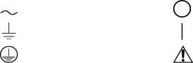
Power Supply Safety Markings
Alternating Current |
Off (Supply) |
Earth (Ground) Terminal |
On (Supply) |
|
Caution (Check manual for |
Protective Conductor Terminal |
additional information.) |
viii |
Operating Manual for Multichannel Functionality (GPIB-M) |
Table of Contents
About This Manual . . . . . . . . . . . . . . . . . . . . . . . . . . . . . . . . . . . . . . . . . . . . . . . . . . . vii List of Tables . . . . . . . . . . . . . . . . . . . . . . . . . . . . . . . . . . . . . . . . . . . . . . . . . . . . . . . xiii List of Figures . . . . . . . . . . . . . . . . . . . . . . . . . . . . . . . . . . . . . . . . . . . . . . . . . . . . . . . xv
Section 1. Features and Specifications
Description . . . . . . . . . . . . . . . . . . . . . . . . . . . . . . . . . . . . . . . . . . . . . . . . . . . . . . . . . 17
Features and Functions . . . . . . . . . . . . . . . . . . . . . . . . . . . . . . . . . . . . . . . . . . . . . . . 17
Features. . . . . . . . . . . . . . . . . . . . . . . . . . . . . . . . . . . . . . . . . . . . . . . . . . . . . . . 17
Programmable Functions. . . . . . . . . . . . . . . . . . . . . . . . . . . . . . . . . . . . . . . . . . 18
Readback Functions . . . . . . . . . . . . . . . . . . . . . . . . . . . . . . . . . . . . . . . . . . . . . 18
Specifications . . . . . . . . . . . . . . . . . . . . . . . . . . . . . . . . . . . . . . . . . . . . . . . . . . . . . . . 19
Section 2. Installation and Configuration
Introduction . . . . . . . . . . . . . . . . . . . . . . . . . . . . . . . . . . . . . . . . . . . . . . . . . . . . . . . . . 25 Initial Inspection . . . . . . . . . . . . . . . . . . . . . . . . . . . . . . . . . . . . . . . . . . . . . . . . . . . . . 25
Basic Setup Procedure . . . . . . . . . . . . . . . . . . . . . . . . . . . . . . . . . . . . . . . . . . . . . . . . 31 Setup Procedure . . . . . . . . . . . . . . . . . . . . . . . . . . . . . . . . . . . . . . . . . . . . . . . . 32 Power On Service Request . . . . . . . . . . . . . . . . . . . . . . . . . . . . . . . . . . . . . . . . 33
Configure for GPIB Operation. . . . . . . . . . . . . . . . . . . . . . . . . . . . . . . . . . . . . . . . . . . 34 Change Remote Control Source . . . . . . . . . . . . . . . . . . . . . . . . . . . . . . . . . . . . 34 Set GPIB Address . . . . . . . . . . . . . . . . . . . . . . . . . . . . . . . . . . . . . . . . . . . . . . . 34
Configure for Multichannel Operation . . . . . . . . . . . . . . . . . . . . . . . . . . . . . . . . . . . . . 35 Multichannel Connections . . . . . . . . . . . . . . . . . . . . . . . . . . . . . . . . . . . . . . . . . 35 Multichannel Configuration. . . . . . . . . . . . . . . . . . . . . . . . . . . . . . . . . . . . . . . . . 35 CANbus . . . . . . . . . . . . . . . . . . . . . . . . . . . . . . . . . . . . . . . . . . . . . . . . . . . . . . . 36 CANbus Cables . . . . . . . . . . . . . . . . . . . . . . . . . . . . . . . . . . . . . . . . . . . . . . . . . 36 Configuration of CAN-only Interface Cards . . . . . . . . . . . . . . . . . . . . . . . . . . . . 36 Setup . . . . . . . . . . . . . . . . . . . . . . . . . . . . . . . . . . . . . . . . . . . . . . . . . . . . . . . . . 37 Using Multichannel Operation . . . . . . . . . . . . . . . . . . . . . . . . . . . . . . . . . . . . . . 37 Multichannel Commands . . . . . . . . . . . . . . . . . . . . . . . . . . . . . . . . . . . . . . . . . . 38 Broadcasting Commands. . . . . . . . . . . . . . . . . . . . . . . . . . . . . . . . . . . . . . . . . . 39 Specifications. . . . . . . . . . . . . . . . . . . . . . . . . . . . . . . . . . . . . . . . . . . . . . . . . . . 39
User Lines. . . . . . . . . . . . . . . . . . . . . . . . . . . . . . . . . . . . . . . . . . . . . . . . . . . . . . . . . . 40 User Lines Connection (XT, HPD, XPD) . . . . . . . . . . . . . . . . . . . . . . . . . . . . . . 41
Section 3. Operation
Overview. . . . . . . . . . . . . . . . . . . . . . . . . . . . . . . . . . . . . . . . . . . . . . . . . . . . . . . . . . . 43
Powering ON the Power Supply. . . . . . . . . . . . . . . . . . . . . . . . . . . . . . . . . . . . . 43
Power Supply Operating States . . . . . . . . . . . . . . . . . . . . . . . . . . . . . . . . . . . . . . . . . 44
Power-On. . . . . . . . . . . . . . . . . . . . . . . . . . . . . . . . . . . . . . . . . . . . . . . . . . . . . . 44
Output Shutdown . . . . . . . . . . . . . . . . . . . . . . . . . . . . . . . . . . . . . . . . . . . . . . . . 44
Soft Start . . . . . . . . . . . . . . . . . . . . . . . . . . . . . . . . . . . . . . . . . . . . . . . . . . . . . . 44
Normal Operation. . . . . . . . . . . . . . . . . . . . . . . . . . . . . . . . . . . . . . . . . . . . . . . . 44
Calibration . . . . . . . . . . . . . . . . . . . . . . . . . . . . . . . . . . . . . . . . . . . . . . . . . . . . . 44
Release 2.1 |
ix |
Power Supply Regulation Modes. . . . . . . . . . . . . . . . . . . . . . . . . . . . . . . . . . . . . . . . 45 Constant Voltage (CV) . . . . . . . . . . . . . . . . . . . . . . . . . . . . . . . . . . . . . . . . . . . 45 Constant Current (CC) . . . . . . . . . . . . . . . . . . . . . . . . . . . . . . . . . . . . . . . . . . . 45 Automatic Mode Crossover . . . . . . . . . . . . . . . . . . . . . . . . . . . . . . . . . . . . . . . . 45
Remote Control Modes . . . . . . . . . . . . . . . . . . . . . . . . . . . . . . . . . . . . . . . . . . . . . . . 46 Front Panel LEDs. . . . . . . . . . . . . . . . . . . . . . . . . . . . . . . . . . . . . . . . . . . . . . . . . . . . 47
Power Supply Operation . . . . . . . . . . . . . . . . . . . . . . . . . . . . . . . . . . . . . . . . . . . . . . 48 Change Remote/Local Mode. . . . . . . . . . . . . . . . . . . . . . . . . . . . . . . . . . . . . . . 48 Power On Remote State . . . . . . . . . . . . . . . . . . . . . . . . . . . . . . . . . . . . . . . . . . 49 Enable Output . . . . . . . . . . . . . . . . . . . . . . . . . . . . . . . . . . . . . . . . . . . . . . . . . . 49 Set Voltage and Current . . . . . . . . . . . . . . . . . . . . . . . . . . . . . . . . . . . . . . . . . . 49 Readback . . . . . . . . . . . . . . . . . . . . . . . . . . . . . . . . . . . . . . . . . . . . . . . . . . . . . 50 Configure Output Protection . . . . . . . . . . . . . . . . . . . . . . . . . . . . . . . . . . . . . . . 51 OVP. . . . . . . . . . . . . . . . . . . . . . . . . . . . . . . . . . . . . . . . . . . . . . . . . . . . . . . . . . 52 Fold Protection . . . . . . . . . . . . . . . . . . . . . . . . . . . . . . . . . . . . . . . . . . . . . . . . . 52 Additional Protections . . . . . . . . . . . . . . . . . . . . . . . . . . . . . . . . . . . . . . . . . . . . 53 Set Shutdown Recovery for AC Off. . . . . . . . . . . . . . . . . . . . . . . . . . . . . . . . . . 53 AC Off Protection . . . . . . . . . . . . . . . . . . . . . . . . . . . . . . . . . . . . . . . . . . . . . . . 53 Over Temperature Protection . . . . . . . . . . . . . . . . . . . . . . . . . . . . . . . . . . . . . . 53 Clear Protection Event . . . . . . . . . . . . . . . . . . . . . . . . . . . . . . . . . . . . . . . . . . . 54 Shutdown vs Protection Alarm . . . . . . . . . . . . . . . . . . . . . . . . . . . . . . . . . . . . . 54 User Settings (Save and Recall) . . . . . . . . . . . . . . . . . . . . . . . . . . . . . . . . . . . . 55 Set Up Power ON Defaults . . . . . . . . . . . . . . . . . . . . . . . . . . . . . . . . . . . . . . . . 56 Power On Output State . . . . . . . . . . . . . . . . . . . . . . . . . . . . . . . . . . . . . . . . . . . 57 Reset. . . . . . . . . . . . . . . . . . . . . . . . . . . . . . . . . . . . . . . . . . . . . . . . . . . . . . . . . 57 Read Error Messages . . . . . . . . . . . . . . . . . . . . . . . . . . . . . . . . . . . . . . . . . . . . 58 Clear Status. . . . . . . . . . . . . . . . . . . . . . . . . . . . . . . . . . . . . . . . . . . . . . . . . . . . 58 Configure Auxiliary Status Lines . . . . . . . . . . . . . . . . . . . . . . . . . . . . . . . . . . . . 58
Auto Sequencing . . . . . . . . . . . . . . . . . . . . . . . . . . . . . . . . . . . . . . . . . . . . . . . . . . . . 60 Programming a Sequence. . . . . . . . . . . . . . . . . . . . . . . . . . . . . . . . . . . . . . . . . 60 Deleting a Sequence. . . . . . . . . . . . . . . . . . . . . . . . . . . . . . . . . . . . . . . . . . . . . 63 Using Auto Sequencing. . . . . . . . . . . . . . . . . . . . . . . . . . . . . . . . . . . . . . . . . . . 63 Set V, I, and P Limits. . . . . . . . . . . . . . . . . . . . . . . . . . . . . . . . . . . . . . . . . . . . . 65 Triggered Setpoints. . . . . . . . . . . . . . . . . . . . . . . . . . . . . . . . . . . . . . . . . . . . . . 65 Triggering Commands. . . . . . . . . . . . . . . . . . . . . . . . . . . . . . . . . . . . . . . . . . . . 66 Slew Rate . . . . . . . . . . . . . . . . . . . . . . . . . . . . . . . . . . . . . . . . . . . . . . . . . . . . . 67 Identification Query . . . . . . . . . . . . . . . . . . . . . . . . . . . . . . . . . . . . . . . . . . . . . . 68 Option Identification Query . . . . . . . . . . . . . . . . . . . . . . . . . . . . . . . . . . . . . . . . 68 SCPI Version Query . . . . . . . . . . . . . . . . . . . . . . . . . . . . . . . . . . . . . . . . . . . . . 68
Section 4. Status Registers
Overview . . . . . . . . . . . . . . . . . . . . . . . . . . . . . . . . . . . . . . . . . . . . . . . . . . . . . . . . . . 69
Condition Register. . . . . . . . . . . . . . . . . . . . . . . . . . . . . . . . . . . . . . . . . . . . . . . 69
Event Register. . . . . . . . . . . . . . . . . . . . . . . . . . . . . . . . . . . . . . . . . . . . . . . . . . 69
Enable Register. . . . . . . . . . . . . . . . . . . . . . . . . . . . . . . . . . . . . . . . . . . . . . . . . 69
Transition Filters . . . . . . . . . . . . . . . . . . . . . . . . . . . . . . . . . . . . . . . . . . . . . . . . 69
OPERation Status Register. . . . . . . . . . . . . . . . . . . . . . . . . . . . . . . . . . . . . . . . 69
REGulating Sub-Register . . . . . . . . . . . . . . . . . . . . . . . . . . . . . . . . . . . . . . . . . 72
x |
Operating Manual for Multichannel Functionality (GPIB-M) |
SHUTdown Sub-Register. . . . . . . . . . . . . . . . . . . . . . . . . . . . . . . . . . . . . . . . . . 73
Protection SHUTdown Sub-Register . . . . . . . . . . . . . . . . . . . . . . . . . . . . . . . . . 73
Remote CONtrol Sub-Register. . . . . . . . . . . . . . . . . . . . . . . . . . . . . . . . . . . . . . 73
Current SHare Sub-Register . . . . . . . . . . . . . . . . . . . . . . . . . . . . . . . . . . . . . . . 74
QUEStionable Status Register. . . . . . . . . . . . . . . . . . . . . . . . . . . . . . . . . . . . . . 74
VOLTage Sub-Register . . . . . . . . . . . . . . . . . . . . . . . . . . . . . . . . . . . . . . . . . . . 76
CURRent Sub-Register . . . . . . . . . . . . . . . . . . . . . . . . . . . . . . . . . . . . . . . . . . . 77
Standard Event Status Register. . . . . . . . . . . . . . . . . . . . . . . . . . . . . . . . . . . . . 77
Status Byte. . . . . . . . . . . . . . . . . . . . . . . . . . . . . . . . . . . . . . . . . . . . . . . . . . . . . 79
Master Summary Status (MSS) . . . . . . . . . . . . . . . . . . . . . . . . . . . . . . . . . . . . . 80
Request Service (RQS) . . . . . . . . . . . . . . . . . . . . . . . . . . . . . . . . . . . . . . . . . . . 80
Status Register Commands . . . . . . . . . . . . . . . . . . . . . . . . . . . . . . . . . . . . . . . . . . . . 81
SCPI Status Commands . . . . . . . . . . . . . . . . . . . . . . . . . . . . . . . . . . . . . . . . . . 81
IEEE 488.2 Status and Event Commands . . . . . . . . . . . . . . . . . . . . . . . . . . . . . 82
Operation Status Register Commands . . . . . . . . . . . . . . . . . . . . . . . . . . . . . . . 85
Regulating Sub-Register Commands. . . . . . . . . . . . . . . . . . . . . . . . . . . . . . . . . 85
Shutdown Sub-Register Commands . . . . . . . . . . . . . . . . . . . . . . . . . . . . . . . . . 85
Protection Shutdown Sub-Register Commands. . . . . . . . . . . . . . . . . . . . . . . . . 86
Remote Control Sub-Register Commands. . . . . . . . . . . . . . . . . . . . . . . . . . . . . 86
Current Share Sub-Register Commands . . . . . . . . . . . . . . . . . . . . . . . . . . . . . . 87
Questionable Status Register Commands. . . . . . . . . . . . . . . . . . . . . . . . . . . . . 87
Voltage Sub-Register Commands . . . . . . . . . . . . . . . . . . . . . . . . . . . . . . . . . . . 88
Current Sub-Register Commands . . . . . . . . . . . . . . . . . . . . . . . . . . . . . . . . . . . 88
Section 5. Current Sharing
Overview. . . . . . . . . . . . . . . . . . . . . . . . . . . . . . . . . . . . . . . . . . . . . . . . . . . . . . . . . . . 89
Theory of Operation . . . . . . . . . . . . . . . . . . . . . . . . . . . . . . . . . . . . . . . . . . . . . . 90
Configure Current Share . . . . . . . . . . . . . . . . . . . . . . . . . . . . . . . . . . . . . . . . . . 90
Setup Current Sharing Network . . . . . . . . . . . . . . . . . . . . . . . . . . . . . . . . . . . . . 90
Operation . . . . . . . . . . . . . . . . . . . . . . . . . . . . . . . . . . . . . . . . . . . . . . . . . . . . . . . . . . 91
Errors . . . . . . . . . . . . . . . . . . . . . . . . . . . . . . . . . . . . . . . . . . . . . . . . . . . . . . . . . 91
Appendix A. GPIB
Overview. . . . . . . . . . . . . . . . . . . . . . . . . . . . . . . . . . . . . . . . . . . . . . . . . . . . . . . . . . . 93
Codes and Standards . . . . . . . . . . . . . . . . . . . . . . . . . . . . . . . . . . . . . . . . . . . . . . . . . 93
Message Terminators . . . . . . . . . . . . . . . . . . . . . . . . . . . . . . . . . . . . . . . . . . . . . . . . . 93
Address Range . . . . . . . . . . . . . . . . . . . . . . . . . . . . . . . . . . . . . . . . . . . . . . . . . . . . . . 93
Primary. . . . . . . . . . . . . . . . . . . . . . . . . . . . . . . . . . . . . . . . . . . . . . . . . . . . . . . . 93
Secondary . . . . . . . . . . . . . . . . . . . . . . . . . . . . . . . . . . . . . . . . . . . . . . . . . . . . . 93
Service Request and Polling. . . . . . . . . . . . . . . . . . . . . . . . . . . . . . . . . . . . . . . . . . . . 93
Protocol Specifications . . . . . . . . . . . . . . . . . . . . . . . . . . . . . . . . . . . . . . . . . . . . . . . . 94
Multiline Control Functions. . . . . . . . . . . . . . . . . . . . . . . . . . . . . . . . . . . . . . . . . 94
Interface Functions. . . . . . . . . . . . . . . . . . . . . . . . . . . . . . . . . . . . . . . . . . . . . . . 94
Electrical Specifications . . . . . . . . . . . . . . . . . . . . . . . . . . . . . . . . . . . . . . . . . . . . . . . 95
Driver Requirements . . . . . . . . . . . . . . . . . . . . . . . . . . . . . . . . . . . . . . . . . . . . . 95
Mechanical Specifications . . . . . . . . . . . . . . . . . . . . . . . . . . . . . . . . . . . . . . . . . . . . . 95
Performance Specifications . . . . . . . . . . . . . . . . . . . . . . . . . . . . . . . . . . . . . . . . . . . . 95
Release 2.1 |
xi |
Appendix B. SCPI Command Reference
Overview . . . . . . . . . . . . . . . . . . . . . . . . . . . . . . . . . . . . . . . . . . . . . . . . . . . . . . . . . . 97
Codes and Standards . . . . . . . . . . . . . . . . . . . . . . . . . . . . . . . . . . . . . . . . . . . . . . . . 97
IEEE 488.2 Requirements. . . . . . . . . . . . . . . . . . . . . . . . . . . . . . . . . . . . . . . . . 97
SCPI Requirements. . . . . . . . . . . . . . . . . . . . . . . . . . . . . . . . . . . . . . . . . . . . . . 97
IEEE-488.2/SCPI Syntax and Style . . . . . . . . . . . . . . . . . . . . . . . . . . . . . . . . . . . . . . 98
Parameters . . . . . . . . . . . . . . . . . . . . . . . . . . . . . . . . . . . . . . . . . . . . . . . . . . . . 98
Understanding SCPI Commands. . . . . . . . . . . . . . . . . . . . . . . . . . . . . . . . . . . . . . . . 99
SCPI Command Hierarchy . . . . . . . . . . . . . . . . . . . . . . . . . . . . . . . . . . . . . . . . 99
Using SCPI Commands . . . . . . . . . . . . . . . . . . . . . . . . . . . . . . . . . . . . . . . . . . 99
Parameter Types. . . . . . . . . . . . . . . . . . . . . . . . . . . . . . . . . . . . . . . . . . . . . . . 102
SCPI Command Summary. . . . . . . . . . . . . . . . . . . . . . . . . . . . . . . . . . . . . . . . . . . . 103
Notations Used in the Tables . . . . . . . . . . . . . . . . . . . . . . . . . . . . . . . . . . . . . 103
Expressions . . . . . . . . . . . . . . . . . . . . . . . . . . . . . . . . . . . . . . . . . . . . . . . . . . . . . . . 115
Appendix C. Error Messages
Overview . . . . . . . . . . . . . . . . . . . . . . . . . . . . . . . . . . . . . . . . . . . . . . . . . . . . . . . . . 117 Command Error List. . . . . . . . . . . . . . . . . . . . . . . . . . . . . . . . . . . . . . . . . . . . . . . . . 118 Execution Error List . . . . . . . . . . . . . . . . . . . . . . . . . . . . . . . . . . . . . . . . . . . . . . . . . 118 Device-Specific Error List. . . . . . . . . . . . . . . . . . . . . . . . . . . . . . . . . . . . . . . . . . . . . 120 Query Error List . . . . . . . . . . . . . . . . . . . . . . . . . . . . . . . . . . . . . . . . . . . . . . . . . . . . 121 User Request Event. . . . . . . . . . . . . . . . . . . . . . . . . . . . . . . . . . . . . . . . . . . . . . . . . 121 Operation Complete Event. . . . . . . . . . . . . . . . . . . . . . . . . . . . . . . . . . . . . . . . . . . . 121 Front Panel Error Codes . . . . . . . . . . . . . . . . . . . . . . . . . . . . . . . . . . . . . . . . . . . . . 122 CPU Error Codes . . . . . . . . . . . . . . . . . . . . . . . . . . . . . . . . . . . . . . . . . . . . . . . . . . . 122 Analog Programming Interface Error codes. . . . . . . . . . . . . . . . . . . . . . . . . . . . . . . 122 Auto Sequencing Error Codes . . . . . . . . . . . . . . . . . . . . . . . . . . . . . . . . . . . . . . . . . 122 CANbus Error Codes . . . . . . . . . . . . . . . . . . . . . . . . . . . . . . . . . . . . . . . . . . . . . . . . 123 Multichannel Error Codes . . . . . . . . . . . . . . . . . . . . . . . . . . . . . . . . . . . . . . . . . . . . 123 Current Share Error Codes . . . . . . . . . . . . . . . . . . . . . . . . . . . . . . . . . . . . . . . . . . . 124
Appendix D. Calibration
Overview . . . . . . . . . . . . . . . . . . . . . . . . . . . . . . . . . . . . . . . . . . . . . . . . . . . . . . . . . 125
Entering Calibration Mode . . . . . . . . . . . . . . . . . . . . . . . . . . . . . . . . . . . . . . . . . . . . 125 Security code. . . . . . . . . . . . . . . . . . . . . . . . . . . . . . . . . . . . . . . . . . . . . . . . . . 126
Setup and Equipment . . . . . . . . . . . . . . . . . . . . . . . . . . . . . . . . . . . . . . . . . . . . . . . 126
Calibration Procedure . . . . . . . . . . . . . . . . . . . . . . . . . . . . . . . . . . . . . . . . . . . . . . . 127 Output Voltage . . . . . . . . . . . . . . . . . . . . . . . . . . . . . . . . . . . . . . . . . . . . . . . . 127 Output Current. . . . . . . . . . . . . . . . . . . . . . . . . . . . . . . . . . . . . . . . . . . . . . . . . 128
Exit calibration mode . . . . . . . . . . . . . . . . . . . . . . . . . . . . . . . . . . . . . . . . . . . . . . . . 129 Restore Factory Calibration . . . . . . . . . . . . . . . . . . . . . . . . . . . . . . . . . . . . . . . . . . . 129
xii |
Operating Manual for Multichannel Functionality (GPIB-M) |
List of Tables
Table 1.1 Specifications for HPD 300 W with GPIB-M or CANbus . . . . . . . . . . . 19 Table 1.2 Specifications for XFR 1200 W with GPIB-M or CANbus . . . . . . . . . . 20 Table 1.3 Specifications for XFR 2800 W with GPIB-M or CANbus . . . . . . . . . . 21 Table 1.4 Specifications for XHR 1000 W with GPIB-M or CANbus . . . . . . . . . . 22 Table 1.5 Specifications for XPD 500 W with GPIB-M or CANbus . . . . . . . . . . . 23 Table 1.6 Specifications for XT 60 W with GPIB-M or CANbus . . . . . . . . . . . . . 23 Table 2.1 Remote Mode Power On Conditions . . . . . . . . . . . . . . . . . . . . . . . . . . 33 Table 2.2 CANbus Pins . . . . . . . . . . . . . . . . . . . . . . . . . . . . . . . . . . . . . . . . . . . . 36 Table 2.3 User Line Pins . . . . . . . . . . . . . . . . . . . . . . . . . . . . . . . . . . . . . . . . . . . 40 Table 3.1 Power Supply Factory Defaults . . . . . . . . . . . . . . . . . . . . . . . . . . . . . . 46 Table 3.2 Features Affected by Reset (*RST) Command . . . . . . . . . . . . . . . . . . 57 Table 4.1 OPERation Status Register . . . . . . . . . . . . . . . . . . . . . . . . . . . . . . . . . 72 Table 4.2 REGulating Sub-Register . . . . . . . . . . . . . . . . . . . . . . . . . . . . . . . . . . 72 Table 4.3 SHUTdown Sub-Register . . . . . . . . . . . . . . . . . . . . . . . . . . . . . . . . . . 73 Table 4.4 Protection SHUTdown Sub-Register . . . . . . . . . . . . . . . . . . . . . . . . . . 73 Table 4.5 Remote CONtrol Sub-Register . . . . . . . . . . . . . . . . . . . . . . . . . . . . . . 74 Table 4.6 Current SHare Sub-Register . . . . . . . . . . . . . . . . . . . . . . . . . . . . . . . . 74 Table 4.7 QUEStionable Status Register . . . . . . . . . . . . . . . . . . . . . . . . . . . . . . 76 Table 4.8 VOLTage Sub-Register . . . . . . . . . . . . . . . . . . . . . . . . . . . . . . . . . . . . 76 Table 4.9 CURRent Sub-Register . . . . . . . . . . . . . . . . . . . . . . . . . . . . . . . . . . . . 77 Table 4.10 Standard Event Status Register . . . . . . . . . . . . . . . . . . . . . . . . . . . . . 78 Table 4.11 Status Byte Summary Register . . . . . . . . . . . . . . . . . . . . . . . . . . . . . . 79 Table 4.12 Preset Values of User Configurable Registers . . . . . . . . . . . . . . . . . . 81 Table A.1 Multiline Control Functions . . . . . . . . . . . . . . . . . . . . . . . . . . . . . . . . . 94 Table A.2 Interface Functions . . . . . . . . . . . . . . . . . . . . . . . . . . . . . . . . . . . . . . . 94 Table A.3 Driver Types for Interface Lines. . . . . . . . . . . . . . . . . . . . . . . . . . . . . . 95 Table B.1 IEEE 488.2 Commands . . . . . . . . . . . . . . . . . . . . . . . . . . . . . . . . . . . 104 Table B.2 Readback Commands . . . . . . . . . . . . . . . . . . . . . . . . . . . . . . . . . . . . 105 Table B.3 Commands for Output Control. . . . . . . . . . . . . . . . . . . . . . . . . . . . . . 106 Table B.4 Commands for Current Share . . . . . . . . . . . . . . . . . . . . . . . . . . . . . . 107 Table B.5 Commands for Calibration. . . . . . . . . . . . . . . . . . . . . . . . . . . . . . . . . 107 Table B.6 Command to Clear all Protection Mechanisms . . . . . . . . . . . . . . . . . 107 Table B.7 Commands for Fold Protection . . . . . . . . . . . . . . . . . . . . . . . . . . . . . 108 Table B.8 Commands for Triggering . . . . . . . . . . . . . . . . . . . . . . . . . . . . . . . . . 108 Table B.9 System Commands . . . . . . . . . . . . . . . . . . . . . . . . . . . . . . . . . . . . . . 108 Table B.10 Status Commands . . . . . . . . . . . . . . . . . . . . . . . . . . . . . . . . . . . . . . . 109
Release 2.1 |
xiii |
List of Tables
Table B.11 Protection Commands . . . . . . . . . . . . . . . . . . . . . . . . . . . . . . . . . . . 112 Table B.12 User Lines. . . . . . . . . . . . . . . . . . . . . . . . . . . . . . . . . . . . . . . . . . . . . 112 Table B.13 Output State . . . . . . . . . . . . . . . . . . . . . . . . . . . . . . . . . . . . . . . . . . . 112 Table B.14 Auto Sequence Commands . . . . . . . . . . . . . . . . . . . . . . . . . . . . . . . 113 Table B.15 Expressions . . . . . . . . . . . . . . . . . . . . . . . . . . . . . . . . . . . . . . . . . . . 115 Table C.1 Command Error List . . . . . . . . . . . . . . . . . . . . . . . . . . . . . . . . . . . . . 118 Table C.2 Execution Error List. . . . . . . . . . . . . . . . . . . . . . . . . . . . . . . . . . . . . . 118 Table C.3 Device-Specific Error List . . . . . . . . . . . . . . . . . . . . . . . . . . . . . . . . . 120 Table C.4 Query Error List. . . . . . . . . . . . . . . . . . . . . . . . . . . . . . . . . . . . . . . . . 121 Table C.5 User Request Event . . . . . . . . . . . . . . . . . . . . . . . . . . . . . . . . . . . . . 121 Table C.6 Operation Complete Event . . . . . . . . . . . . . . . . . . . . . . . . . . . . . . . . 121 Table C.7 Front Panel Error Codes. . . . . . . . . . . . . . . . . . . . . . . . . . . . . . . . . . 122 Table C.8 CPU Error Codes . . . . . . . . . . . . . . . . . . . . . . . . . . . . . . . . . . . . . . . 122 Table C.9 Analog Programming Interface Error code . . . . . . . . . . . . . . . . . . . . 122 Table C.10 Auto Sequencing Error Codes . . . . . . . . . . . . . . . . . . . . . . . . . . . . . 122 Table C.11 CANbus Error Codes . . . . . . . . . . . . . . . . . . . . . . . . . . . . . . . . . . . . 123 Table C.12 Multichannel Error Codes . . . . . . . . . . . . . . . . . . . . . . . . . . . . . . . . . 123 Table C.13 Current Share Error Codes. . . . . . . . . . . . . . . . . . . . . . . . . . . . . . . . 124
xiv |
Operating Manual for Multichannel Functionality (GPIB-M) |
List of Figures
Figure 2.1 XFR and XHR Power Supply Front Panel with GPIB-M Interface . . . . 26 Figure 2.2 XPD Power Supply Front Panel with GPIB Interface. . . . . . . . . . . . . . 27 Figure 2.3 XT and HPD Power Supply Front Panel with GPIB Interface . . . . . . . 27 Figure 2.4 XFR 2800 Watt Power Supply Rear Panel with GPIB-M Interface . . . 28 Figure 2.5 XFR 1200 Watt Power Supply Rear Panel with GPIB-M Interface . . . 28 Figure 2.6 XHR Power Supply Rear Panel with GPIB-M Interface. . . . . . . . . . . . 29 Figure 2.7 XPD Power Supply Rear Panel with GPIB-M Interface. . . . . . . . . . . . 29 Figure 2.8 XT/HPD Power Supply Rear Panel with GPIB-M Interface . . . . . . . . . 30 Figure 2.9 XFR GPIB Cable with Ferrite Block. . . . . . . . . . . . . . . . . . . . . . . . . . . 31 Figure 2.10 Connections for Multichannel Operation . . . . . . . . . . . . . . . . . . . . . . . 37 Figure 2.11 User Signals Connector (XT, HPD and XPD) . . . . . . . . . . . . . . . . . . . 41 Figure 2.12 XT, HPD, XPD User Cable with Ferrite Block . . . . . . . . . . . . . . . . . . . 41 Figure 2.13 Schematic For User Line Interface . . . . . . . . . . . . . . . . . . . . . . . . . . . 42 Figure 4.1 Operation Status Registers . . . . . . . . . . . . . . . . . . . . . . . . . . . . . . . . . 71 Figure 4.2 Questionable Status Registers . . . . . . . . . . . . . . . . . . . . . . . . . . . . . . 75 Figure 4.3 IEEE 488.2 Status Register and Status Byte. . . . . . . . . . . . . . . . . . . . 77 Figure 5.1 Example of Current Share Operation . . . . . . . . . . . . . . . . . . . . . . . . . 89
Release 2.1 |
xv |
List of Figures
xvi |
Operating Manual for Multichannel Functionality (GPIB-M) |
Section 1. Features and Specifications
Description
The internal GPIB-M interface card allows you to operate your power supply from a computer controller via the IEEE-488 communications bus.
The GPIB-M interface allows complete remote programming of your power supply, including status reporting, settings query, and service request generation with user-designated conditions. Both the voltage and current output are precisely programmed directly in volts and amps with 16-bit resolution. Additionally, the 16-bit readbacks measure the actual power supply output. The programming command set is easy to use and includes software calibration commands. The interface card comes with several protection features such as programmable over and under voltage protection, and soft limits.
Multichannel addressing via CANbus allows up to 50 power supplies to be controlled from one GPIB address. This manual covers operation of both the GPIB-M and CAN-only interface cards.
Features and Functions
Features • 16-bit programming and readback of voltage and current
•Programmable soft limits for voltage and current
•LED status signals: remote operation, service request and shutdown; (XFR and XHR only) error, addressed, over voltage protection, auxiliary status bits
•Software calibration
•Automatic voltage/current mode crossover
•Shutdown or warning for overand under-programmed trip points
•Programmable auxiliary status lines for monitoring power supply conditions
•Remote interlock and trigger lines
•Selectable standby, programmed sequence and other power-on defaults
•Active current sharing with parallel connected units for higher power requirements
•CANbus communications link for multichannel addressing, and master/slave current sharing
•Extensive SCPI command set for control and status monitoring
Release 2.1 |
17 |
Features and Specifications
Features and Functions
Programmable |
• |
Output voltage and current |
Functions |
• |
Soft limits for voltage and current |
|
• |
Overvoltage protection |
|
• |
Output enable/disable |
|
• Ten, 99-step auto sequences for easy programming of complex test routines |
|
|
• |
Ten stored settings |
|
• Five load protection mechanisms including fold protection in CV or CC mode |
|
Readback |
• |
Actual measured voltage and current |
Functions |
• |
Voltage and current settings |
|
• Soft voltage and current limits |
|
|
• |
Overvoltage protection setting |
|
• |
Programming error codes |
|
• Power supply model and version identification |
|
|
• |
Firmware revision levels |
18 |
Operating Manual for Multichannel Functionality (GPIB-M) |
Features and Specifications
Specifications
Specifications
The specifications in this section are warranted at 25°C ±5°C unless otherwise specified. All specifications are subject to change without notice.
Table 1.1 Specifications for HPD 300 W with GPIB-M or CANbus
Models |
15-20 |
30-10 |
60-5 |
Program Resolution |
|
|
|
Voltage |
2.4mV |
4.7mV |
9.3mV |
Current |
2.8mA |
1.4mA |
0.7mA |
|
|
|
|
Program Accuracy1 |
|
|
|
Voltage |
60mV |
70mV |
90mV |
|
±0.1% |
±0.1% |
±0.12% |
Current |
75mA |
50mA |
25mA |
|
±0.12% |
±0.12% |
±0.1% |
Readback Resolution |
|
|
|
Voltage |
2.4mV |
4.7mV |
9.3mV |
Current |
2.8mA |
1.4mA |
0.7mA |
Readback Accuracy1 |
|
|
|
Voltage |
45mV |
90mV |
175mV |
|
±0.3% |
±0.3% |
±0.3% |
Current |
75mA |
40mA |
25mA |
|
±0.12% |
±0.12% |
±0.1% |
1.Apply accuracy specifications according to the following voltage program accuracy example: Set a model HPD 15-20 power supply to 10 volts.
The expected result will be within the range of 10 volts ± 60mV ± 0.1% of the set voltage of 10 volts.
Release 2.1 |
19 |

Features and Specifications
Specifications
Table 1.2 Specifications for XFR 1200 W with GPIB-M or CANbus
Models |
7.5-140 |
12-100 |
20-60 |
35-35 |
40-30 |
Program Resolution |
|
|
|
|
|
Voltage |
1.16mV |
1.8mV |
3.08mV |
5.4mV |
6.2mV |
Current |
19.6mA |
14mA |
8.4mA |
5.4mA |
4.2mA |
Program Accuracy1 |
|
|
|
|
|
Voltage |
10mV |
50mV |
75mV |
75mV |
75mV |
|
±0.12% |
±0.12% |
±0.12% |
±0.3% |
±0.3% |
Current |
500mA |
460mA |
250mA |
200mA |
150mA |
|
±0.1% |
±0.1% |
±0.1% |
±0.1% |
±0.15% |
|
|
|
|
|
|
Readback Resolution |
|
|
|
|
|
Voltage |
1.16mV |
1.8mV |
3.08mV |
5.4mV |
6.2mV |
Current |
19.6mA |
14mA |
8.4mA |
5.4mA |
4.2mA |
|
|
|
|
|
|
Readback Accuracy1 |
|
|
|
|
|
Voltage |
30mV |
60mV |
75mV |
75mV |
75mV |
|
±0.12% |
±0.12% |
±0.12% |
±0.3% |
±0.3% |
Current |
500mA |
460mA |
250mA |
200mA |
150mA |
|
±0.1% |
±0.1% |
±0.1% |
±0.1% |
±0.15% |
Models |
60-20 |
100-12 |
150-8 |
300-4 |
600-2 |
Program Resolution |
|
|
|
|
|
Voltage |
9.2mV |
15.4mV |
23.1mV |
46.2mV |
92.4mV |
Current |
2.8mA |
1.68mA |
1.12mA |
0.56mA |
0.28mA |
Program Accuracy1 |
|
|
|
|
|
Voltage |
150mV |
150mV |
225mV |
225mV |
250mV |
|
±0.25% |
±0.35% |
±0.35% |
±0.35% |
±0.35% |
Current |
120mA |
80mA |
80mA |
80mA |
50mA |
|
±0.1% |
±0.1% |
±0.1% |
±0.1% |
±0.1% |
Readback Resolution |
|
|
|
|
|
Voltage |
9.2mV |
15.4mV |
23.1mV |
46.2mV |
92.4mV |
Current |
2.8mA |
1.68mA |
1.12mA |
0.56mA |
0.28mA |
Readback Accuracy1 |
|
|
|
|
|
Voltage |
150mV |
150mV |
225mV |
225mV |
250mV |
|
±0.25% |
±0.35% |
±0.35% |
±0.35% |
±0.35% |
Current |
120mA |
80mA |
80mA |
80mA |
50mA |
|
±0.1% |
±0.1% |
±0.1% |
±0.1% |
±0.1% |
1.Apply accuracy specifications according to the following voltage program accuracy example: Set a model XFR 20-60 power supply to 10 volts.
The expected result will be within the range of 10 volts ± 75mV ± 0.12% of the set voltage of 10 volts.
20 |
Operating Manual for Multichannel Functionality (GPIB-M) |

Features and Specifications
Specifications
Table 1.3 Specifications for XFR 2800 W with GPIB-M or CANbus
Models |
7.5-300 |
12-220 |
20-130 |
33-85 |
40-70 |
Program Resolution |
|
|
|
|
|
Voltage |
1.16mV |
1.8mV |
3.08mV |
5.1mV |
6.2mV |
Current |
42.0mA |
30.8mA |
18.2mA |
13.0mA |
9.8mA |
Program Accuracy1 |
|
|
|
|
|
Voltage |
10mV |
50mV |
75mV |
75mV |
75mV |
|
±0.12% |
±0.12% |
±0.12% |
±0.3% |
±0.3% |
Current |
900mA |
750mA |
500mA |
425mA |
350mA |
|
±0.1% |
±0.1% |
±0.1% |
±0.1% |
±0.15% |
|
|
|
|
|
|
Readback Resolution |
|
|
|
|
|
Voltage |
1.16mV |
1.8mV |
3.08mV |
5.1mV |
6.2mV |
Current |
42.0mA |
30.8mA |
18.2mA |
13.0mA |
9.8mA |
|
|
|
|
|
|
Readback Accuracy |
|
|
|
|
|
Voltage |
30mV |
60mV |
75mV |
75mV |
75mV |
|
±0.12% |
±0.12% |
±0.12% |
±0.3% |
±0.3% |
Current |
900mA |
750mA |
500mA |
425mA |
350mA |
|
±0.1% |
±0.1% |
±0.1% |
±0.1% |
±0.1% |
Models |
60-46 |
100-28 |
150-18 |
300-9 |
600-4 |
Program Resolution |
|
|
|
|
|
Voltage |
9.2mV |
15.4mV |
23.1mV |
46.2mV |
92.4mV |
Current |
6.44mA |
3.92mA |
2.52mA |
1.26mA |
0.56mA |
Program Accuracy1 |
|
|
|
|
|
Voltage |
150mV |
150mV |
225mV |
225mV |
250mV |
|
±0.25% |
±0.35% |
±0.35% |
±0.35% |
±0.35% |
Current |
250mA |
140mA |
120mA |
80mA |
80mA |
|
±0.1% |
±0.1% |
±0.1% |
±0.1% |
±0.1% |
Readback Resolution |
|
|
|
|
|
Voltage |
9.2mV |
15.4mV |
23.1mV |
46.2mV |
92.4mV |
Current |
6.44mA |
3.92mA |
2.52mA |
1.26mA |
0.56mA |
Readback Accuracy1 |
|
|
|
|
|
Voltage |
150mV |
150mV |
225mV |
225mV |
250mV |
|
±0.25% |
±0.35% |
±0.35% |
±0.35% |
±0.35% |
Current |
250mA |
140mA |
120mA |
80mA |
80mA |
|
±0.1% |
±0.15% |
±0.1% |
±0.1% |
±0.1% |
1.Apply accuracy specifications according to the following voltage program accuracy example:
Set a model XFR 20-130 power supply to 10 volts.
The expected result will be within the range of 10 volts ± 75mV ± 0.12% of the set voltage of 10 volts
Release 2.1 |
21 |

Features and Specifications
Specifications
Table 1.4 Specifications for XHR 1000 W with GPIB-M or CANbus
Models |
7.5-130 |
20-50 |
33-33 |
40-25 |
60-18 |
Program Resolution |
|
|
|
|
|
Voltage |
1.16mV |
1.8mV |
3.08mV |
6.2mV |
9.2mV |
Current |
42.0mA |
30.8mA |
18.2mA |
9.8mA |
6.44mA |
Program Accuracy1 |
|
|
|
|
|
Voltage |
10mV |
50mV |
75mV |
75mV |
150mV |
|
±0.12% |
±0.12% |
±0.12% |
±0.3% |
±0.25% |
Current |
900mA |
750mA |
500mA |
350mA |
250mA |
|
±0.1% |
±0.1% |
±0.1% |
±0.1% |
±0.1% |
|
|
|
|
|
|
Readback Resolution |
|
|
|
|
|
Voltage |
1.16mV |
1.8mV |
3.08mV |
6.2mV |
9.2mV |
Current |
42.0mA |
30.8mA |
18.2mA |
9.8mA |
6.44mA |
|
|
|
|
|
|
Readback Accuracy1 |
|
|
|
|
|
Voltage |
30mV |
60mV |
75mV |
75mV |
150mV |
|
±0.12% |
±0.12% |
±0.12% |
±0.3% |
±0.25% |
Current |
900mA |
750mA |
500mA |
350mA |
250mA |
|
±0.1% |
±0.1% |
±0.1% |
±0.1% |
±0.1% |
Models |
100-10 |
150-7 |
300-3.5 |
600-1.7 |
Program Resolution |
|
|
|
|
Voltage |
15.4mV |
23.1mV |
46.2mV |
92.4mV |
Current |
3.92mA |
2.52mA |
1.26mA |
0.56mA |
Program Accuracy1 |
|
|
|
|
Voltage |
150mV |
225mV |
225mV |
250mV |
|
±0.35% |
±0.35% |
±0.35% |
±0.35% |
Current |
140mA |
120mA |
80mA |
80mA |
|
±0.15% |
±0.1% |
±0.1% |
±0.1% |
Readback Resolution |
|
|
|
|
Voltage |
15.4mV |
23.1mV |
46.2mV |
92.4mV |
Current |
3.92mA |
2.52mA |
1.26mA |
0.56mA |
Readback Accuracy1 |
|
|
|
|
Voltage |
150mV |
225mV |
225mV |
250mV |
|
±0.35% |
±0.35% |
±0.35% |
±0.35% |
Current |
140mA |
120mA |
80mA |
80mA |
|
±0.15% |
±0.1% |
±0.1% |
±0.1% |
1.Apply accuracy specifications according to the following voltage program accuracy example:
Set a model XHR 20-50 power supply to 10 volts.
The expected result will be within the range of 10 volts ± 50mV ± 0.12% of the set voltage of 10 volts.
22 |
Operating Manual for Multichannel Functionality (GPIB-M) |

Features and Specifications
Specifications
Table 1.5 Specifications for XPD 500 W with GPIB-M or CANbus
Models |
7.5-67 |
18-30 |
33-16 |
60-9 |
120-4.5 |
Program Resolution |
|
|
|
|
|
Voltage |
1.2mV |
4.6mV |
5.1mV |
9.3mV |
18.6mV |
Current |
5.2mA |
3.6mA |
2.9mA |
1.3mA |
0.7mA |
Program Accuracy1 |
10mV |
75mV |
75mV |
150mV |
180mV |
Voltage |
|||||
|
±0.12% |
±0.12% |
±0.12% |
±0.3% |
±0.25% |
Current |
250mA |
140mA |
115mA |
80mA |
80mA |
|
±0.1% |
±0.1% |
±0.15% |
±0.15% |
±0.1% |
|
|
|
|
|
|
Readback Resolution |
|
|
|
|
|
Voltage |
1.2mV |
4.6mV |
5.1mV |
9.3mV |
18.6mV |
Current |
5.2mA |
3.6mA |
2.4mA |
1.3mA |
0.7mA |
|
|
|
|
|
|
Readback Accuracy1 |
|
|
|
|
|
Voltage |
30mV |
75mV |
75mV |
150mV |
180mV |
|
±0.12% |
±0.12% |
±0.2% |
±0.3% |
±0.25% |
Current |
250mA |
140mA |
115mA |
80mA |
80mA |
|
±0.1% |
±0.1% |
±0.15% |
±0.15% |
±0.1% |
1.Apply accuracy specifications according to the following voltage program accuracy example: Set a model XPD 18-30 power supply to 10 volts.
The expected result will be within the range of 10 volts ± 75mV ± 0.12% of the set voltage of 10 volts.
Table 1.6 Specifications for XT 60 W with GPIB-M or CANbus
Models |
7-6 |
15-4 |
20-3 |
30-2 |
60-1 |
120-0.5 |
250-0.25 |
Program Resolution |
|
|
|
|
|
|
|
Voltage |
1.1mV |
2.4mV |
3.1mV |
4.7mV |
9.3mV |
17mV |
17mV |
Current |
1.0mA |
0.6mA |
0.5mA |
0.3mA |
0.2mA |
0.1mA |
0.1mA |
|
|
|
|
|
|
|
|
Program Accuracy1 |
|
|
|
|
|
|
|
Voltage |
10mV |
20mV |
20mV |
30mV |
200mV |
400mV |
400mV |
|
±0.1% |
±0.1% |
±0.15% |
±0.15% |
±0.15% |
±0.15% |
±0.15% |
Current |
110mA |
70mA |
50mA |
40mA |
26mA |
13mA |
13mA |
|
±0.15% |
±0.15% |
±0.15% |
±0.15% |
±0.2% |
±0.2% |
±0.2% |
Readback Resolution |
|
|
|
|
|
|
|
Voltage |
1.1mV |
2.4mV |
3.1mV |
4.7mV |
9.3mV |
17mV |
17mV |
Current |
1.0mA |
0.6mA |
0.5mA |
0.3mA |
0.2mA |
0.1mA |
0.1mA |
Readback Accuracy1 |
|
|
|
|
|
|
|
Voltage |
10mV |
10mV |
10mV |
15mV |
35mV |
70mV |
70mV |
|
±0.15% |
±0.1% |
±0.1% |
±0.1% |
±0.15% |
±0.15% |
±0.15% |
Current |
110mA |
70mA |
50mA |
40mA |
26mA |
13mA |
13mA |
|
±0.15% |
±0.15% |
±0.15% |
±0.15% |
±0.2% |
±0.2% |
±0.2% |
1.Apply accuracy specifications according to the following voltage program accuracy example: Set a model XT 15-4 power supply to 10 volts.
The expected result will be within the range of 10 volts ± 20mV ± 0.1% of the set voltage of 10 volts.
Release 2.1 |
23 |
Features and Specifications
Specifications
24 |
Operating Manual for Multichannel Functionality (GPIB-M) |

Section 2. Installation and Configuration
Introduction
To use this product, you must have the following equipment:
•a compatible model of DC output power supply
•IEEE-488 connector and cable
•computer with an IEEE-488 interface card
•Computer-based communications software package
•parallel CANbus cables (to connect power supply for multichannel operation)
The GPIB or CANbus interface is usually installed in a power supply at the factory. Your local distributor or service center can also install the interface, especially for use in a previously-purchased supply already on site. The interface card will be calibrated and configured with default settings. You will need to configure the supply for your system using the “Basic Setup Procedure” on page 31. Refer also to Figure 2.1, pg. 26, Figure 2.2, pg. 27 and Figure 2.3, pg. 27 for drawings of the front panels. The interface subplate is different for each product. Please check Figure 2.4 to Figure 2.7.
Initial Inspection
CAUTION
If you remove the unit's cover, use proper static control techniques to avoid damage to static-sensitive components on the printed circuit board.
On first receiving your unit, perform a quick inspection.
•Ensure each package contains a power supply with its GPIB interface board installed, and manuals for the power supply and the GPIB interface. A custom CANbus cable and a terminator are also supplied with each GPIB-M or CAN-only interface. Any additional parts shipped with the power supply will be identified in the supply's documentation.
•Inspect the unit for any signs of physical damage such as scratches, cracks, or broken switches, connectors, or displays.
•Check the printed circuit board and components if you suspect internal damage.
If the unit is damaged, save all packing materials and notify the carrier immediately. For additional information, please see the section titled, “Returning Power Supplies to the Manufacturer” in the manual shipped with your complete unit.
Release 2.1 |
25 |
Installation and Configuration
Initial Inspection
CAUTION
Use proper static control techniques to avoid damage to static-sensitive components on the printed circuit board.
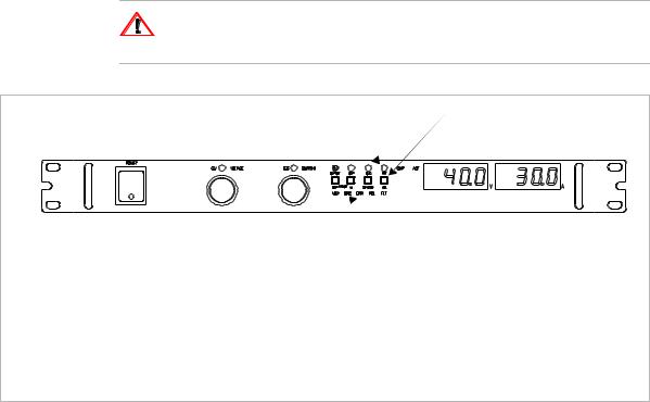
Remote LED (REM) |
Local Switch (LOCAL) |
Remote Programming LEDs: |
|
Address LED (ADR) |
Fault LED (FLT) |
Indicates that the master controller is addressing the unit. |
Used to indicate AUX B status is TRUE. |
Service Request LED (SRQ) |
Polarity LED (POL) |
Comes on at power up if the PON SRQ is set to on. |
Used to indicate AUX A status is TRUE. |
Error LED (ERR) |
|
Indicates when a programming error has occurred. You |
|
can clear the ERR LED with an error query command. |
|
Figure 2.1 XFR and XHR Power Supply Front Panel with GPIB-M Interface
(XFR 1200 Watt model shown)
26 |
Operating Manual for Multichannel Functionality (GPIB-M) |
Installation and Configuration
Initial Inspection
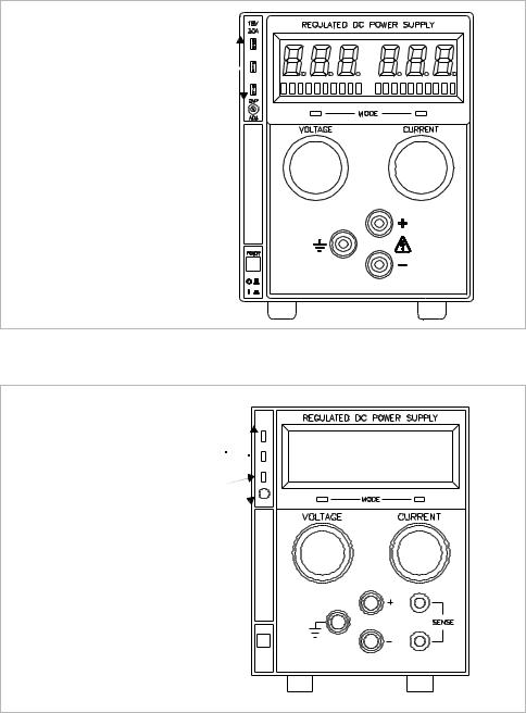
Service Request LED (SRQ) 
Remote LED (REM) 

Shutdown LED (S/D)
Figure 2.2 XPD Power Supply Front Panel with GPIB Interface
Remote Mode (REM) LED 
Service Request (SRQ) LED 
Over Voltage Protection (OVP) LED
OVP Potentiometer
Figure 2.3 XT and HPD Power Supply Front Panel with GPIB Interface
Release 2.1 |
27 |

Installation and Configuration
Initial Inspection
GPIB |
CANBUS |
USER LINES |
1
Figure 2.4 XFR 2800 Watt Power Supply Rear Panel with GPIB-M Interface
|
USER LINES |
CANBUS |
GPIB |
1 |
|
|
|
Figure 2.5 |
XFR 1200 Watt Power Supply Rear Panel with GPIB-M Interface |
||
28 |
Operating Manual for Multichannel Functionality (GPIB-M) |
Loading...