


OWNER'S MANUAL
FLEET POWER INVERTER/BATTERY CHARGERS
FLEET POWER 1000
FLEET POWER 2000 UL
C ®
FLEET POWER 2500
KKK
Fleet Power 1000 & 2000 models are certified by UL to comply with FED spec-KKK-A1822, SAE spec-SAE-JRR1, for emergency vehicle application. All models UL and C-UL Listed for Canadian use.
90-0115-00 10/97 Fltman.pm65

INTRODUCTION
General safety information for installation and operation is contained throughout this manual where it applies and are not included in this summary.
Warnings Warning statements identify conditions or practices which could result in personal injury, loss of life, damage to equipment or other property.
Fuse Replacement For continued protection against the possibility of fire, replace the fuse only with a fuse of the specified voltage, current and type rating.
Power Source To avoid damage, operate the equipment only within the specified AC (line) and DC (battery) voltages.
Servicing To reduce the risk of electric shock do not open this unit. There are no user serviceable parts inside. Refer all servicing to qualified personnel.
The statements, specifications and instructions in this publication are believed to be correct. No warranty is made, expressed or implied by the seller or manufacturer with respect to any results or lack thereof from the use of information in this publication and no liability is assumed for any direct or consequential damages, personal loss or injury. All statements made herein are strictly to be used or relied on at the user's risk.
© 1997 Heart Interface Corporation. All rights reserved.
2
90-0115-00
10/97 Fltman.pm65

TABLE OF CONTENTS
Introduction . . . . . . . . . . . . . . . . . . . . . . . . . . 4
Things You Should Know . . . . . . . . . . . . . . . 5
Circuit Breaker Protection
Electronic Protection
Power Sharing
Power Switch
Remote Control Programming
Operation . . . . . . . . . . . . . . . . . . . . . . . . . . . . 6
Remote Control Panel . . . . . . . . . . . . . . . . . . 7
Remote Power Switch
System Status LEDs
DC Volts Bargraph
DC Amps Bargraph
Dip Switches
Equalize or 3-Stage Charging
Battery Type
Auto Range
Power Sharing
Dip Switch Status
Remote Control Wiring
Link 2000 Remote Control
Status LEDs . . . . . . . . . . . . . . . . . . . . . . . . . 10 Dip Switch Programming . . . . . . . . . . 11
Batteries . . . . . . . . . . . . . . . . . . . . 12
Battery Types
Battery Interconnection
Battery Bank Ratings and Sizing
Battery Charging . . . . . . . . . . . . . . . . . . 16
Conventional Battery Chargers
Fleet Power Battery Charger
Charging Over-Discharged Batteries
Battery Charger Voltage Table . . . . . . . . . . 21
Installation Precautions . . . . . . . . . . . . . . . 22
Installation . . . . . . . . . . . . . . . . . . . . . . . 23
Key Installation Points
Location
Grounding
Neutral Bonding
AC Wiring
Ground Fault Circuit Interrupters
Remote Control Wiring
DC Wiring
Battery Cable Fusing
Installation Options . . . . . . . . . . . . . . . . . . 29 DC Wiring Options . . . . . . . . . . . . . . . . . . . 32 Troubleshooting . . . . . . . . . . . . . . . . . . . . . .34 Glossary . . . . . . . . . . . . . . . . . . . . . . . . . 36 Specifications . . . . . . . . . . . . . . . . . . . 38 Warranty . . . . . . . . . . . . . . . . . . . . . . 40
3
90-0115-00 10/97 Fltman.pm65

INTRODUCTION
This owner's manual describes the Fleet Power Inverter/Chargers from Heart
Interface. These units perform three distinct functions:
1.DC to AC power inverting.
2.Automatic transfer switching between inverter power and incoming AC power.
3.Automatic 3-Stage Battery charging plus manual battery equalizing.
4.AC to DC power converter.
• The inverters provide regulated 120 Volt AC power and crystal controlled frequency at 60Hz from a deep cycle battery bank in specified watts:
FP 1000-12................ |
1000 watts |
FP 2000-12................ |
2000 watts |
FP 2500-12................ |
2500 watts |
The output is a modified sinewave and is compatible with appliances, tools and other 120 VAC equipment. Momentary surge power of three times the inverter rating is available for starting electric motors. High efficiency insures the longest possible battery life between recharges.
• The transfer switch allows the Fleet Power Inverter/Chargers to be connected to an external AC source and transfer the source through to the loads. When disconnected, the transfer switch allows automatic switching back to the inverter.
Fleet Power Inverter/Chargers operate as self-contained backup power systems, just add batteries.
• Fleet Power battery chargers are electronically controlled and rated:
FP 1000-12.................. |
50 |
Amps DC |
FP 2000-12................ |
100 |
Amps DC |
FP 2500-12................ |
130 |
Amps DC |
They are designed to rapidly and optimally recharge either wet* or gel* cell deep-cycle batteries. Battery charging is accomplished in 3 automatic stages: Bulk Charge, Acceptance Charge and Float Charge. In addition, using the remote control, a manually-en- gaged Equalizing Charge cycle is possible.
With an external AC source connected, the Fleet Power charger also serves the functions of a AC to DC converter to supply all of the DC loads which are connected to the battery.
Simple, automatic operation is made possible by the microprocessor in the Fleet Power Inverter/Chargers. In most cases, the unit is left on and no attention or maintenance is required.
*Adustable with optional remote
4
90-0115-00
10/97 Fltman.pm65

THINGS YOU SHOULD KNOW
The optional Fleet Power Remote Control Panel provides a power switch, system status LEDs, DC Volts and DC Amps
LED bargraphs. On the back of the remote is a set of dip switches which allow adjustment of the following:
•Manual Initiation of Equalize Charging
•Ambient Battery Temperature
•Battery Type
•Charger Mode (Auto or Controlled)
•Power Sharing
Circuit Breaker Protection
Fleet Power Inverter/Chargers are circuit breaker protected.
The Fleet Power 1000 has a 12 Amp INV/CHG circuit breaker on the front of the unit that protects against sustained inverter overloads over 1440 watts and the AC input to the battery charger. The 15 Amp INPUT circuit breaker on the unit protects the incoming AC circuit which is transferred through to the loads via the GFCI.
The Fleet Power 2000 has a 25 Amp INV/CHG circuit breaker that protects against sustained inverter overloads over 3000 watts and the AC input to the battery charger. .
The Fleet Power 2500 has a 30 Amp OUTPUT circuit breaker on the unit that protects against sustained inverter overloads over 3600 watts. The 30 Amp circuit breaker protects the incoming AC leg which feeds the battery charger.
The 30 Amp TRANSFER circuit breaker
on the units protect the incoming AC circuit which is transferred through to the loads connected by the hardwire output.
The 15 Amp circuit breaker protects the
GFCI outlet on the Fleet Power 1000 and 2000 models. When a circuit breaker trips, the circuit breaker is reset by pushing the button back in.
Electronic Protection
Fast acting electronic circuits protect the inverter from extreme overloads and short circuits. Other protection includes a low and high battery cutoff and automatic shutdown if over temperature occurs. The fault condition must be eliminated before reset will occur. Example: remove overload, recharge batteries or allow to cool. Reset by cycling the power switch OFF/ON.
Power Sharing
When connected to shorepower or using a generator, the battery charger and transfer functions are engaged. A unique power sharing feature automatically reduces the AC consumption of the battery charger allowing necessary AC power to the load. This prevents the circuit breaker from tripping. This feature can be adjusted using the remote control panel. This feature is set at the transfer rating of each unit by default.
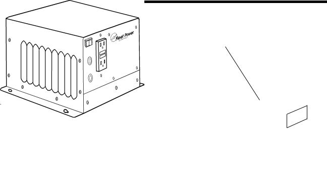
INPUT
INV/CHG
GFCI
5
Fleet Power 2000 shown.
90-0115-00 10/97 Fltman.pm65
OPERATION
Power Switch
The Power Switch is located on the Power Switch front panel. This switch controls ON/OFF
and RESET for the inverter. Expect a 3 second delay when the power switch is turned ON before the unit is activated.
If the unit is connected to external AC power, the battery charger and transfer switch will continue to function, regardless of the position of the switch.
When external AC power is removed and the power switch is in the ON position, the inverter will automatically be ON. If the switch is in the OFF position and external AC power is removed, the inverter will be
OFF. Fleet Power 1000 shown.
Inverter overload protection, transfer switching, power sharing and battery charger regulation will all function automatically.
If installed with the remote control panel, the power switch on the unit should be left in the OFF position. Refer to Remote Control Panel, page 7.
6
90-0115-00
10/97 Fltman.pm65

REMOTE CONTROL PANEL
An optional remote control panel is available which offers several features not found on the unit. The remote control panel provides LED bargraphs which show system status, battery voltage, and DC Amps in both inverter and charge modes. These bargraphs can also display dip switch positions and shut down conditions.
Remote Power Switch
The switch on the remote is used to control the inverter and can also be used to control the battery charger function. When a remote control is used, the power switch on the inverter should be left in the OFF position.
System Status LEDs
These 4 LEDs monitor the system as described in the table on page 10.
DC Volts Bargraph
These LEDs indicate battery voltage as measured inside the unit. Each LED segment indicates .5 Volts. If an overload occurs and the unit shuts down, the DC
Volts bargraph will stop indicating battery voltage and display the dip switch settings.
It will return to indicating battery voltage only after the unit has been reset.
DC Amps Bargraph
These LEDs approximate DC input current in inverter mode and DC output current in battery charger mode. Two ranges are used -- below 50 Amps each segment represents a 10 Amp increment, above 50 Amps each segment represents a 20 Amp increment. Above 130 Amps, a flashing LED segment indicates the value displayed plus 100 Amps (flashing 50 LED is equal to 50 + 100 or 150 Amps DC).
If a shutdown occurs, the DC Amps bargraph will stop indicating DC Amps and will indicate the type of problem . Each LED segment indicates a different problem as described in the troubleshooting section on page 34.
7
90-0115-00 10/97 Fltman.pm65

REMOTE CONTROL PANEL
Dip Switches
On the back of the Fleet Power remote control panel is a set of 8 dip switches which are used to make several adjustments. On the switch block, each switch is numbered . . .1 through 8 and the ON position is indicated. The switch settings can be changed at any time, even while the unit is operating. Following is a discussion of each adjustment. Refer to the table on page 11 for dip switch programming.
BACK VIEW
Fleet Power Remote Control Panel
SWITCH 1 - Manual Equalizing Cycling this switch ON for 1 second, then OFF, will initiate an equalizing charge cycle. The battery charger must be engaged before cycling the switch. The dip switch must always be returned to the OFF position. If it is left ON, an equalizing charge cycle will initiate every time the charger is engaged - this could cause battery damage.
The equalizing cycle is timed to last 8 hours from the time the switch is cycled, at which point the charger resumes normal charging in the float stage.
8
The battery LED blinks when equalizing. See page 18 for a discussion of the theory and procedure for battery equalizing.
SWITCH #2 & #3 - Battery Type Gel cell and wet cell batteries have slightly different charge voltage requirements. Optimum battery charging is temperature dependent. For these reasons, the dip switches allow four different battery charger voltage set points, depending on battery type and ambient temperature:
Cool Wet Cell |
< 80 degrees F. |
Warm Wet Cell |
> 80 degrees F. |
Cool Gel Cell |
< 80 degrees F. |
Warm Gel Cell |
> 80 degrees F. |
Refer to the table on page 21 for the specific voltages for each setting.
SWITCH #4 - Auto Charge With the switch in the OFF position, the remote panel ON/ OFF switch only controls the inverter operation. With the switch turned ON, it allows the power ON/OFF switch on the front of the remote to control the battery charger as well as the inverter.
SWITCH #5 & #6 - Not used for adjustments.
SWITCH #7 & #8 - Power Sharing These switches should be set to match the value of the circuit breaker which protects the incoming AC power. They may also limit the output current from the battery charger.
90-0115-00
10/97 Fltman.pm65

REMOTE CONTROL PANEL
Use the 5 Amp setting for small generators, or for charging deeply discharged batteries.
Dip Switch Status
You can check the position of the dip switches by quickly cycling the power switch OFF/ON twice. The DC Volts bargraph will cease to display battery voltage and will indicate the settings of each dip switch. In this mode the bottom LED will illuminate if switch 1 is on; the second LED will illuminate if switch 2 is on, etc. Dip switch settings are indicated for 10 seconds after which time the display returns to indicating battery voltage.
Factory default settings for all dip switches are in the Off position.
Remote Control Wiring
The remote control panel is supplied with 25 or 50 ft. of telephone cable. The cable supplied may be 6 conductor, however, only 4 conductor is required. You may buy standard 4 conductor telephone cable and run up to 50 ft., if desired. Use only a single length of telephone wire, do not splice.
Refer to page 11 for the Dip Switch
Programming chart.
9
90-0115-00 10/97 Fltman.pm65

STATUS LEDs
Status LED |
Purpose |
|
|
|
|
INV/CHRG |
Power on light. It will be illuminated whenever the |
|
power switch is on (inverter on) or when there is |
||
(Inverter/Charg |
||
|
incoming AC power and the charger comes on. |
|
|
Illuminates when incoming AC power has been |
|
AC Input |
applied and the transfer relays have engaged. |
|
There is a 7-12 second delay from the time the AC |
||
|
||
|
is applied and this LED illuminates. |
|
|
|
|
Steady |
Indicates an over-temperature condition, the unit is |
|
Overload |
shut down. It will reset automatically after cooling. |
|
|
|
|
|
Inverter modeShutdown, diagnose problem using |
|
Blinking |
DC Amps bar graph. Charger modeThermal |
|
Overload |
shutdown, after cooling reset by cycling power |
|
|
switch. |
|
|
|
|
|
This is a High/Low Battery warning condition. |
|
Steady Battery |
Inverter mode: Battery > 15.25 or < 10.50 volts |
|
|
Charger mode: Battery > 15.25 or < 10.00 volts |
|
|
|
|
|
Indicates either a shutdown or equalizing. |
|
|
Battery > 15.50 volts, will auto-reset at 15.25. |
|
Blinking |
Inverter mode: Battery < 10.00 volts, will auto reset |
|
at charger float voltage or upon AC input. |
||
Battery |
||
Charger mode: Battery < 8.00 volts for 1 minute, |
||
|
||
|
remove all DC loads and manually reset by cycling |
|
|
thedisconnectingpower switchand. reapplying shorepower. |
|
|
|
10
90-0115-00
10/97 Fltman.pm65
DIP SWITCH PROGRAMMING
Feature |
Switch |
|
Set Point |
|
||||
Number |
|
|
||||||
|
|
|
|
|
|
|||
|
|
|
|
|
|
|
|
|
|
1 |
|
|
|
|
|
|
|
Equalize or |
|
|
|
|
|
|
|
|
Toggle |
|
|
|
|
|
|
||
3 Stage |
|
Equalize (Do not leave on.) |
|
|||||
On/Off |
|
|
||||||
Charging |
|
|
|
|
|
|
||
|
|
|
|
|
|
|
||
|
Off |
|
3 Stage Charging* |
|
||||
|
|
|
|
|
|
|
|
|
|
2 |
3 |
|
|
|
|
|
|
|
|
|
|
|
|
|
||
|
On |
On |
Warm Gel Cell |
(>80 deg. F.) |
||||
Battery |
|
|
|
|
|
|
|
|
Off |
On |
Cool Gel Cell |
(<80 deg. F.) |
|||||
Type |
||||||||
|
|
|
|
|
|
|
||
|
On |
Off |
Warm Wet Cell |
(>80 deg. F.) |
||||
|
|
|
|
|
|
|
||
|
Off |
Off |
Cool Wet Cell |
(<80 deg. F.)* |
||||
|
|
|
|
|
|
|
|
|
|
4 |
|
|
|
|
|
|
|
|
|
|
|
|
|
|||
Auto |
On |
|
Disable: Charger responds to On/Off |
|||||
|
switch. |
|
|
|
||||
Charge |
|
|
|
|
|
|||
|
|
|
|
|
|
|
||
Off |
|
Enable: Charger on when AC |
|
|||||
|
|
|
||||||
|
|
connected.* |
|
|
|
|||
|
|
|
|
|
|
|||
|
|
|
|
|
|
|
|
|
|
5 |
6 |
Not used. |
|
|
|
||
|
|
|
|
|
|
|
|
|
|
7 |
8 |
1000 |
|
2000 |
|
2500 |
|
|
On |
On |
2.5 Amps |
|
5 Amps |
|
5 Amps |
|
Power |
|
|
|
|
|
|
|
|
Off |
On |
5 Amps |
|
15 Amps |
|
20 Amps |
||
Sharing |
|
|
||||||
|
|
|
|
|
|
|
||
|
On |
Off |
10 Amps |
|
20 Amps |
|
30 Amps |
|
|
|
|
|
|
|
|
|
|
|
Off |
Off |
15 Amps* |
|
30 Amps* |
|
Disabled* |
|
|
|
|
|
|
|
|
|
|
*indicates factory default setting.
11
90-0115-00 10/97 Fltman.pm65

BATTERIES
BATTERY TYPES
Use only deep-cycle batteries with your
Fleet Power Inverter/Charger. These fall into two broad categories, wet cell and gel cell.
Wet Cell Batteries
True deep-cycle wet cell batteries are characterized by relatively thick plates that are alloyed with antimony.
Common marine/RV deep-cycle batteries are acceptable. However, golf cart batteries have better performance and life. They are 6 Volt batteries that must be used in series pairs. High quality marine deep-cycle batteries offer good performance and are available in a wide variety of sizes. Floor sweeper, fork lift or large 2 Volt cells can also offer excellent performance, if their large size can be accommodated.
12
It should be noted that high antimony deep-cycle batteries will give off gas as a natural result of charging and will experience some water loss. It is very important that the electrolyte level be checked frequently and topped off with distilled water when necessary. Never allow the tops of the plates to be exposed to air, as contamination of the cell will result. Keeping the tops of batteries clean will reduce self-discharging. Always provide ventilation for the battery storage compartment.
Do not use car batteries or engine starting batteries of any kind with your inverter/charger. Beware of any battery that is rated in Cold Cranking Amps (CCA). This is a rating which applies only to engine starting batteries. In general, most wet cell batteries that are described as hybrid batteries, suitable for either engine starting or deep-cycle applications, are a compromise and will give limited life if deeply discharged.
Beware of 8-D starting batteries that are commonly used for starting diesel engines. These batteries are not deep-cycle.
90-0115-00
10/97 Fltman.pm65
 Loading...