


MRC88
INSTALLATION INSTRUCTIONS
MODEL MRC88
EIGHT ZONE – EIGHT SOURCE
AUDIO/VIDEO CONTROLLER/AMPLIFIER SYSTEM

Page: 2 Model MRC88
SAFETY INSTRUCTIONS - READ BEFORE OPERATING EQUIPMENT
CAU TION: TO REDUCE THE RISK OF ELECTRIC SHOCK,
DO NOT REMOVE COVER (OR BACK)
NO USER-SERVICEABLE PARTS INSIDE
REFER SERVICING TO QUALIFIED SERVICE PERSONNEL
The lightning flash with arrowhead symbol, within an equilateral triangle,
is intended to alert the user to the presence of un-insulated “dangerous
voltage” within the product’s enclosure that may be of sufficient magnitude
to constitute a risk of electric shock to persons.
The exclamation point within an equilateral triangle is intended to alert the
user to the presence of important operating and maintenance (servicing)
instructions in the literature accompanying the appliance.
WARNING
TO REDUCE THE RISK OF FIRE OR ELECTRIC SHOCK, DO
NOT EXPOSE THIS APPLIANCE TO RAIN OR MOISTURE.
This product was designed and manufactured to meet strict quality and safety standards. There are, however,
some installation and operation precautions, which you should be particularly aware of.
1. Read Instructions – All the safety and operating instruct ions should be read before the appliance is oper ated.
2. Retain Instructions – The safety and operating instructions should be retained for future referenc e.
3. Heed Warnings – All warnings on the appliance and in the operating instructions should be adhered to.
4. Follow Instructions – All operating and use instructions should be followed.
5. Water and Moisture – The appliance should not be used near water – for example, near a bathtub, washbowl, kitchen sink, laundr y
tub, in a wet basement, or near a swimming pool, etc.
6. Carts and Stands – The appliance should be used only with a c art or stand that is recommended by the manufactur er. An appliance
and cart combination should be moved with care. Quick stops, excessive force, and uneven surf aces may caus e the appliance and
cart combination to overturn.
7. Wall or Ceiling Mounting – The appliance should be mounted to a wall or ceiling only as recommended by the manuf acturer.
8. Ventilation – The applianc e should be situated so that its location or position does not interf ere with its pr oper ventilation. For
example, the appliance should not be situated on a bed, sofa, rug, or similar surface that may block the ventilation openings; or,
placed in a built-in installation, such as a bookcase or cabinet that may impede the flow of air through the ventilation openings.
9. Heat – The appliance should be situated away from heat s ources such as radiators, heat registers, stoves, or other appliances
(including amplifiers) that pr oduce heat.
10. Power Sources – The appliance should be connected to a power supply only of the type described in the operating instructions or as
marked on the appliance.
11. Grounding or Polarization – Precautions should be taken so that the grounding or polarization means of an appliance is not
defeated.
12. Power-Cord Protection – Power- supply cords should be r outed so that they are not likely to be walked on or pinched by items
placed upon or against them, paying partic ular attention to cords at plugs, convenience receptacles, and the point wher e they exit from
the appliance.
13. Cleaning – The applianc e should be cleaned only as recommended by the manufacturer.
14. Power Lines – An outdoor antenna should be located away from the power lines.
15. Nonuse Periods – The power cord of the appliance should be unplugged from the outlet when left unused for a long period of time.
16. Object and Liquid Entry – Care should be taken so that objects do not fall and liquids are not spilled into the enclosure through
openings.
17. Damage Requiring Service – The applianc e should be serviced by qualified service personnel when:
A. The P ower-supply c ord or the plug has been damaged; or
B. Objects have fallen, or liquid has spilled into the appliance; or
C. The appliance has been exposed to rain; or
D. The appliance does not appear to operate normally or exhibits a marked change in performance; or
E. The applianc e has been dr opped, or the enclosur e damaged.
18. Servicing – The user should not attempt to service the applianc e beyond that described in the operating instructions. All other
servicing should be referred to qualified s ervice personnel.
© 2003 Xantech Corporation

Model MRC88 Page: 3
TABLE OF CONTENTS
SAFETY INSTRUCTIONS - READ BEFORE OPERATING EQUIPMENT...........................................................2
TABLE OF CONTENTS ............................................................................................................................................ 3
SECTION 1: GENERAL INFORMATION & FEATURES........................................................... 8
GENERAL INFORMATION.....................................................................................................................................8
SYSTEM OVERVIEW............................................................................................................................................. 10
CONTROLLER/AMPLIFIER FEATURES ............................................................................................................ 11
KEYPAD FEATURES.............................................................................................................................................. 12
MRC88 CONTROLLER/AMPLIFIER PANEL AND FEATURE DESCRIPTIONS............................................. 13
MRC88 FRONT PANEL FEATURES AND CONNECTIONS:....................................................................... 13
MRC88 REAR PANEL FEATURES AND CONNECTIONS:......................................................................... 15
MRC88 KEYPAD FEATURE DESCRIPTIONS..................................................................................................... 17
MRC88 KEYPAD - FRONT FEATURES:................................................................................................. 17
MRC88 KEYPAD - REAR FEATURES AND CONNECTIONS:.................................................................... 19
SECTION 2: INSTALLATION & CONNECTIONS.................................................................... 20
INSTALLATION......................................................................................................................................................20
OPERATION: OUT-OF-THE-BOX PRE TEST..................................................................................... 20
MRC88 CONTROLLER/AMPLIFIER PHYSICAL LOCATION AND MOUNTING......................... 21
MRC88 KEYPAD PHYSICAL LOCATION AND MOUNTING........................................................ 22
MRC88 KEYPAD REMOVAL .......................................................................................................... 24
CONNECTING THE MRC88 CONTROLLER/AMPLIFIER................................................................................ 25
SOURCE RELATED CONNECTIONS ....................................................................................................... 25
Source Component Connections.............................................................................................................25
Zone Audio Inputs .................................................................................................................................26
IR Control Connections..........................................................................................................................26
Sense Input Connections ........................................................................................................................26
ZONE RELATED WIRIN G CONNECTIONS .............................................................................................. 27
Speaker Connections..............................................................................................................................27
MRC88 Keypad CAT5 Cable Connections at the MRC88 Controller/Amplifier......................................28
Video Connections.................................................................................................................................28
Status Connections and Common Control Out ........................................................................................28
Preamp Out............................................................................................................................................29
CO1 and CO2 (Zones 7 & 8)..................................................................................................................29
Zone IR .................................................................................................................................................29
AC Power Connections ..........................................................................................................................29
CONNECTIONS AT THE ZONE LOCATION.............................................................................................. 29
Keypad Connections and Jumper Settings...............................................................................................30
ZONE EXPANSION (CONNECTING TWO MRC88 CONTROLLERS).......................................................... 31
Linking Two MRC88 Controller/Amplifier Units...................................................................................32
Connecting Source Components.............................................................................................................32
Speaker Connections..............................................................................................................................34
Video connections..................................................................................................................................34
SETTING-UP THE MRC88 SYSTEM.....................................................................................................................35
SECTION 3: PRE-PROGRAMMING THE MRC88.................................................................... 36
PLANNING THE SYSTEM .....................................................................................................................................37
INSTALLING AND CONFIGURING THE DRAGMRC SOFTWARE................................................................... 37
COMPUTER REQUIREMENTS (MINIMUM) ............................................................................................. 37
INCLUDED HARDWARE & SOFTWARE ITEMS....................................................................................... 38
CONNECTING THE MRC88 CONTROLLER/AMPLIFIER TO THE PC........................................................ 38
© 2003 Xantech Corporation

Page: 4 Model MRC88
DB9 Serial Connection .......................................................................................................................... 38
USB Serial Connection.......................................................................................................................... 38
SOFTWARE INSTALLATION.................................................................................................................. 38
STARTING MRC88 DRAGON DROP-IR™ SOFTWARE........................................................................... 38
SERIAL PORT SELECTION ....................................................................................................................38
VERIFYING COM PORT COMMUNICATION......................................................................................... 39
(“WHO AM I” BASE UNIT VERSION VERIF IC ATION) ............................................................................ 39
STARTING A PROJECT......................................................................................................................................... 39
LEARNING IR COMMANDS (CREATING PALETTE FILES).................................................................................... 40
BUILT-IN IR CODE LIBRARY ............................................................................................................... 40
Testing IR Commands in the IR Library.................................................................................................40
LEARNING IR COMMANDS.................................................................................................................. 41
Using the Palette Editor ......................................................................................................................... 41
Recording Toggle Command Functions ................................................................................................. 42
Editing Function Names in the Palette Editor ......................................................................................... 42
TO RENAME AN EXISTING FUNCTION .................................................................................................. 43
Testing IR Commands in the Palette Editor ............................................................................................ 43
CREAT ING A PALETTE FILE ................................................................................................................. 43
EDITING BRAND, COMPONENT, AND FUNCTION LISTS ...................................................................... 44
Adding Brands.......................................................................................................................................44
Adding Components and Functions........................................................................................................ 44
GETTING SOURCE COMMANDS FROM THE INTERNET .......................................................................... 44
Xantech.com .........................................................................................................................................44
Remote Central.com (Importing CCF Files and Discrete IR Commands) ................................................ 44
ENTERING RS232 COMMANDS (CREATING RS232 COMMAND PALETTE FILES) ................................................ 46
ENTERING RS232 COMMAND STRINGS ............................................................................................... 46
Using the RS232 Palette Editor.............................................................................................................. 46
Testing RS232 Command Strings...........................................................................................................47
CREAT ING AN RS232 PALETTE FILE.................................................................................................... 48
SECTION 4: PROGRAMMING THE CONTROLLER .............................................................. 49
CONFIGURING SOURCE ICONS ON MRC88 KEYPAD LCD............................................................................ 49
ENTERING TEXT DIRECTLY ONTO THE ICONS ......................................................................................50
CREATING NEW ICONS........................................................................................................................ 50
SELECTING ICONS FROM THE ICON GENERATOR .............................................................................. 50
DOWNLOADING SOURCE ICONS TO THE KEYPAD.................................................................................. 50
PLACING COMMANDS ONTO THE VIRTUAL KEYPAD ................................................................................. 51
SELECTING IR PALETTES FROM THE IR CODE LIBRARY....................................................................... 51
SELECTING IR PALETTES .................................................................................................................... 51
SELECTING RS232 COMMAND PALETTES............................................................................................ 51
SELECTING INTERNAL AMPLIFIER COMMANDS ................................................................................... 51
PLACING COMMANDS ON THE VIRTU AL KEYPAD ............................................................................... 51
Programming Sequences (Macros)......................................................................................................... 52
Timed Delays ........................................................................................................................................ 52
Repeat Commands.................................................................................................................................52
Push & Hold (Tiered) Commands ..........................................................................................................53
EDITING BUTTONS (ON THE VIRTUAL KEYPAD) ................................................................................. 53
Delete Key ............................................................................................................................................54
Delete Bank (Zone Level)...................................................................................................................... 54
Delete All (System Level)...................................................................................................................... 54
Punch (Zone Level) ............................................................................................................................... 54
Punch All (System Level) ......................................................................................................................54
Copy ..................................................................................................................................................... 54
© 2003 Xantech Corporation

Model MRC88 Page: 5
Paste......................................................................................................................................................54
EDITING COMMANDS (IN THE MACRO COMMAND LIST WINDOW) ...................................................... 54
IR In Zone .............................................................................................................................................55
Source Output........................................................................................................................................55
Delete ....................................................................................................................................................56
Testing Commands Placed on the Virtual Keypad...................................................................................56
PROGRAMMING POWER MANAGEMENT AND SENSE TRIGGER CODES .................................................56
PROGRAMMING POWER MANAGEM ENT .............................................................................................. 56
PROGRAMMING SENSE TRIGGER CODES ............................................................................................. 58
Programming of Sense input...................................................................................................................58
Polarity and Wiring of Sense Input.........................................................................................................59
Current Sense De-Bounce Settings .........................................................................................................59
TESTING COMMANDS UNDER POWER MANAGEMENT AND SENSE TRIGGERS....................................... 59
ZONE OPTIONS CONFIGURATION ....................................................................................................................60
DEFAULT SETTINGS SET IN BASIC MODE ARE AS FOLLOWS:............................................................... 60
NAME OF ZONE .................................................................................................................................. 60
RC68 CODE GROUP......................................................................................................................... 60
PRE AMP VOLUME ADJUST SETTINGS................................................................................................. 61
IR LOOP BACK SETTINGS.................................................................................................................... 61
TRANSFERRING THE PROJECT .........................................................................................................................62
SECTION 5: ADVANCED/EXPANDED PROGRAMMING ...................................................... 63
CONTROLLER OPTIONS PROGRAMMING ......................................................................................................63
ZONE AUDIO INPUT ............................................................................................................................ 63
IR ROUTING ....................................................................................................................................... 64
BACK-LIGHT CONTROL....................................................................................................................... 64
MODE OF OPERATION ........................................................................................................................ 64
Whole House Mode ...............................................................................................................................64
Priority Lockout Mode ...........................................................................................................................64
EXPANDED OPTIONS ........................................................................................................................... 64
Not Expanded ........................................................................................................................................64
Expanded...............................................................................................................................................64
RS232 SETTINGS ................................................................................................................................65
Baud Rate, Data Bits, Stop Bits amd Parity Settings................................................................................65
Process RS232 Input ..............................................................................................................................65
MONITOR LOCKOUT MODE................................................................................................................. 65
Dynamic Monitor Lockout (Administrator) ............................................................................................66
ZONE LINKING PROGRAMMING.......................................................................................................................67
STATIC ZONE LINK MODE .................................................................................................................. 67
DYNAMIC ZONE LINK MODE .............................................................................................................. 68
LINK ALL DYNAMIC ........................................................................................................................... 69
LINK ALL STATIC ............................................................................................................................... 69
CLEAR ALL ........................................................................................................................................ 69
RS232 INPUT TRANSLATOR................................................................................................................................. 69
PROGRAMMING IR COMMANDS AND SEQUENCES ............................................................................... 70
Selecting IR Palettes from the IR Code Library.......................................................................................70
Selecting IR Palettes ..............................................................................................................................70
Associating RS232 Commands with IR Control Codes ...........................................................................70
Editing Individual Commands................................................................................................................70
Testing Commands in the RS2322 Input Translator ................................................................................70
RC68+ IR CODE TRIGGERED SEQUENCER ......................................................................................................71
Programming RC68+ Triggered Sequences ............................................................................................71
Editing Individual Commands................................................................................................................72
© 2003 Xantech Corporation

Page: 6 Model MRC88
PROGRAMMING INTERNAL AMPLIFIER COMMANDS................................................................................. 72
ZONE EXPANSION (CONNECTING MULTIPLE MRC88 CONTROLLERS).................................................. 74
PROGRAMMING IN EXPANDED MODE............................................................................................... 75
Enabling EXPANDED Mode................................................................................................................. 75
Programming the System....................................................................................................................... 75
PHYSICAL CONNECTIONS IN EXPANDED MODE ................................................................................ 75
RS232 CONTROL WHILE IN EXPANDED MODE..................................................................................... 75
TRANSFERRING A PROJECT TO THE MRC88 ................................................................................................. 77
UPLOADING MRC88 PROJECTS......................................................................................................................... 77
SAVING AND BACKING-UP FILES...................................................................................................................... 78
Automatic Save ..................................................................................................................................... 78
Save Project As ..................................................................................................................................... 78
Backing-Up Project Files ....................................................................................................................... 78
Using Backup Files................................................................................................................................78
Backing-Up SmartPad and Palette Files .................................................................................................78
FIRMWARE UPGRADE OPTIONIS...................................................................................................................... 79
DOWNLOADING FIRMW ARE FILES FROM THE WEB.............................................................................. 79
WARM FIRM WARE UPGRADE .............................................................................................................. 79
COLD FIRMWARE UPGRADE................................................................................................................ 79
SECTION 7: TWEAKING THE SYSTEM................................................................................ 80
TEACHING A HAND-HELD REMOTE TO OPERATE THE MRC88 SYSTEM................................................. 80
TEACHING A HAND-HELD REMOTE USING AN RC68+ HAND-HELD PROGRAMMER .............................80
TEACHING A HAND-HELD REMOTE DIRECTLY FROM DRAGON DROP-IR™ .......................................... 80
MAKING FINE ADJUSTMENTS........................................................................................................................... 81
TRIMMING SOURCE AUDIO INPUT LEVELS .......................................................................................... 81
ZONE ADJUSTMENTS...........................................................................................................................82
KEYPAD ADJUSTMENTS ...................................................................................................................... 82
IR Sensitivity Adjustment ...................................................................................................................... 82
LCD Backlight Adjustment....................................................................................................................82
SECTION 8: OPERATING INSTRUCTIONS .......................................................................... 83
ZONE CONTROL.................................................................................................................................................... 83
POWERING THE ZONE ON AND OFF.....................................................................................................83
SOURCE SLECTION AND CONTROL ...................................................................................................... 83
SETTING THE VOLUME........................................................................................................................ 83
MUTING AND UN-MUTING .................................................................................................................. 83
ACCESSING TIER 2 COMMANDS .......................................................................................................... 83
ZONE SETTINGS.................................................................................................................................................... 84
SYSTEM STATUS ................................................................................................................................. 84
AUDIO ADJUSTMENTS......................................................................................................................... 84
DYNAMIC MONITOR LOCKOUT (PARENTAL CONTROL) .......................................................................84
DYNAMIC ZONE LINK ......................................................................................................................... 84
SECTION 9: APPENDIX............................................................................................................ 86
RS232 CONTROL.................................................................................................................................................... 86
TYPES OF COMMANDS .................................................................................................................. 86
INTERFACING TO THE RS232 COMPORT..................................................................................... 86
ASCII STRING ‘INITIATING’ AND ‘TERMINATING’ CHARACTERS......................................... 86
TROUBLESHOOTING........................................................................................................................................... 94
RS232 AND EXPANSION PIN OUT INFORMATION........................................................................................... 97
SPECIFICATIONS .................................................................................................................................................. 99
CERTIFICATIONS ................................................................................................................................................. 99
© 2003 Xantech Corporation

Model MRC88 Page: 7
© 2003 Xantech Corporation

Page: 8 Model MRC88
Section 1: General Information & Features
GENERAL INFORMATION
The Xantech MRC88 System is the next generation in Whole-house Audio/Video Entertainment (WAVE™)
family of products - the first being the MRC44. This is a revolutionary whole-house audio/video entertainment
distribution, audio amplification and control system.
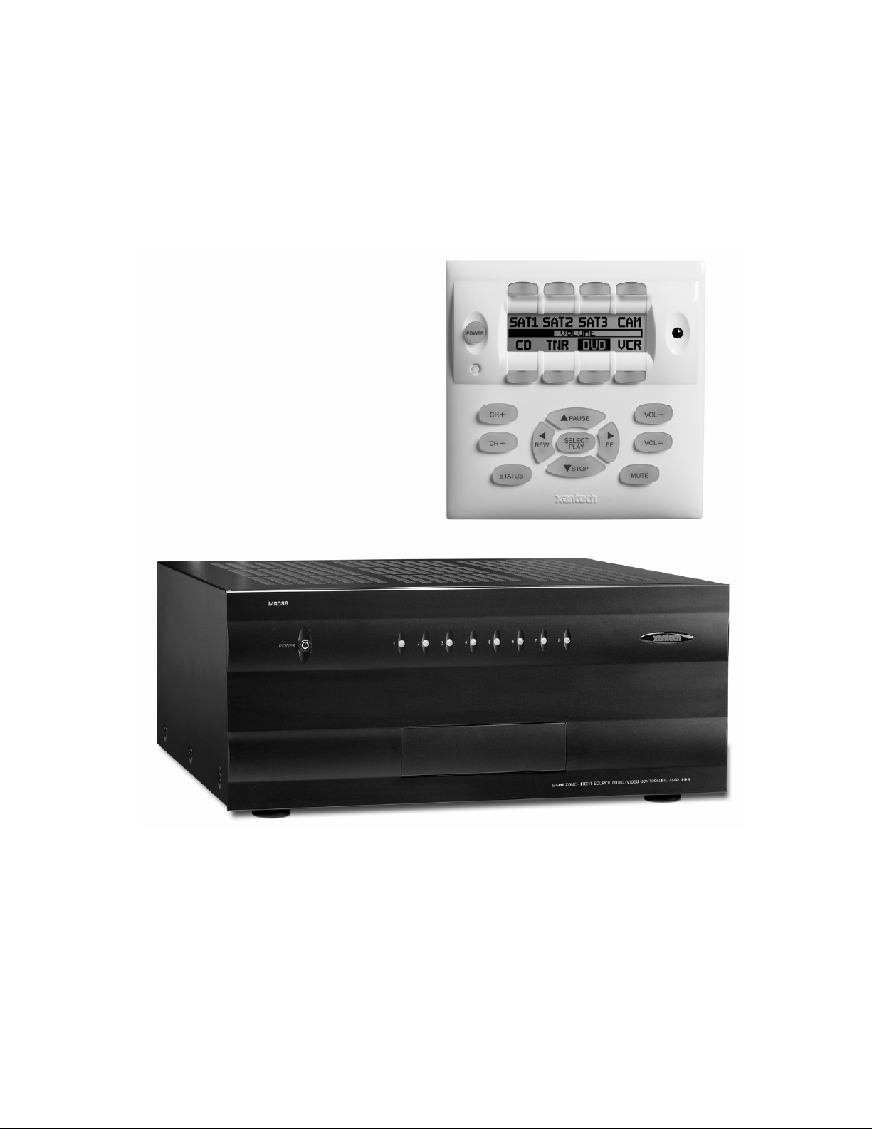
The MRC88 System consists of the MRC88 Controller/Amplifier, Eight LCD Keypads and Eight IR Emitters.
When combined with almost any Eight IR (or RS232) controlled audio/video source components (CD, DVD,
VCR, Satellite, etc.), using the MRC88 System is as easy as pushing a button.
The MRC88 system includes the following components:
• One MRC88 Controller/Amplifier (Part No. MRC88CTL)
• Eight MRC88 Keypads(Part No. MRC88KPW)
• Eight IR Emitters (Part No. 283M)
• One DB9 programming cable to connect to the RS232 serial port on your PC (Part No. 05913410)
• One male DB15 to male DB15 cable with null modem for linking two MRC88 Controllers (Part No.
05913555)
• CD-ROM Disc contains the MRC88 Dragon Drop-IR software (Part No. 03900785-01)
• MRC88 System Installation Instructions (Part No. 08901180)
• Six speaker WECO connector plugs (Part No. 05997400
• 24 Keypad jumpers (for Zone Termination, Keypad Address and IR Sensor Enable)
• MRC88 Keypad Installation Kit which includes Eight sets of installation brackets (Part No. 03079565-01), an
installation template (Part No. 09590255), a Keypad removal tool (Part No. 03025280) and the Keypad
Installation Instructions (Part No. 08901175)
• Caution card
Optional Accessories:
• Secondary Keypads
White: Part No. MRC88KPW
Black: Part No. MRC88KPB
Almond: Part No. MRC88KPA
Ivory: Part No. MRC88KPI
• External IR Receivers
480-00 Dinky Link™ Series IR Receivers
480-80 CFL Friendly Dinky Link™ Series IR Receivers
490-90 Plasma Friendly Micro Link™ Series IR Receivers
780 Series J-Box IR Receivers
291 Series Hidden Link™ IR Receivers
• MRC44CB1 Connecting Block
• CSM1 Current Sensing Module
• URC-2P or URC-2B Universal Hand-Held Remote Controller
© 2003 Xantech Corporation

Model MRC88 Page: 9
IMPORTANT NOTE: A MRC88 System can be a single controller with keypads for up to Eight zones or two
connected controllers and keypads for up to Sixteen zones. There are three different setup modes in the
Dragon Drop-IR Software. The Basic mode allows quick setup and programming for an Eight zone system. It
assumes all zones will use factory defaults and will behave exactly the same. The Advanced mode allows
customization of system configuration for functions such as zone link, monitor lockout, unique IR programming
by zone, etc. The Expanded mode allows programming of systems with more than Eight zones using linked
MRC88 Controllers.
Each section of this manual will indicate which sections apply to the three programming modes and setups. A
section with: BASIC/ADVANCED/EXPANDED would apply to all system configurations. A section with:
ADVANCED/EXPANDED would only apply to systems requiring advanced programming or that have more
than Eight zones, etc.
In the Expanded mode, the controller for zones 1-8 will be referred to as the PRIMARY CONTROLLER. The
controller for zones 9-16 will be referred to as the SECONDARY CONTROLLER.
© 2003 Xantech Corporation
Page: 10 Model MRC88
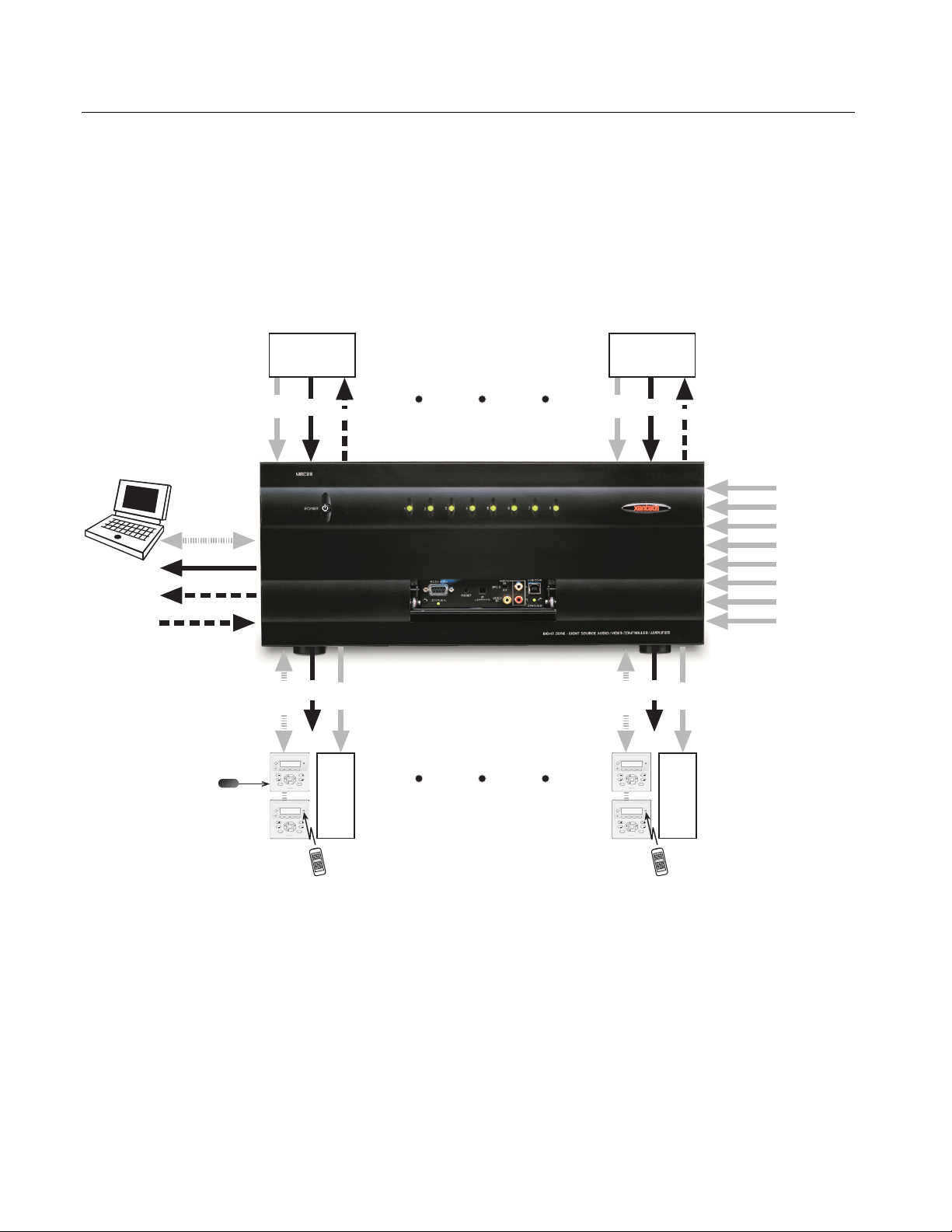
SYSTEM OVERVIEW
The MRC88 is a Eight-source Eight-zone audio/video distribution and control system. The System is comprised
of a Control Amp, Eight LCD Keypads, and Eight 283M IR Emitters. Together the Control Amp and the Keypads
make up a Whole-house Audio/Video Entertainment system. The Control Amp acts as the Server and the
Keypads act as the Clients. The end users interact with the Keypads in order to control all aspects of
Audio/Video Distribution and Control. This System allows the end user to accomplish the following: 1) Distribute
amplified Stereo Audio and Composite Video from Eight independent Sources to Eight separate Zones. 2)
Control the Volume, Mute, Bass, Treble, and Balance for each of the eight Zones. 3) Control most standard
source components via IR and/or RS232 commands. Two Control Amps can be linked to create systems with
up to Sixteen zones.
Audio/Video
Source 1
Audio/Video
Source 8
DB9 / RS232
Common Status
Common IR
IR Learning Eye
Optional
External IR
Receiver
Primary
Keypad
Optional
Secondary
Keypad
Audio
Power
&
Sense
Video
Serial
RJ45RS422
& IR
Zone
Status
Audio
Video
IR
&
Zone 1 Zone 8
POWER
CH
PAUSE
SELECT
CH
PLAY
FF
REW
STOP
STATUS
POWER
CH
PAUSE
SELECT
CH
PLAY
FF
REW
STOP
STATUS
To Built-In
Keypad
IR Receiver
Zone 1
VOL
VOL
Video
MUTE
Monitor
&
Speakers
VOL
VOL
MUTE
Primary
Keypad
Optional
Secondary
Keypad
Figure 1 - System Block Diagram
Audio
&
Video
Serial
RJ45-
RS422
& IR
POWER
CH
CH
STATUS
POWER
CH
CH
STATUS
To Built-In
IR Receiver
PAUSE
SELECT
PLAY
REW
STOP
PAUSE
SELECT
PLAY
REW
STOP
Keypad
FF
FF
Power
Sense
VOL
VOL
MUTE
VOL
VOL
MUTE
Zone
Status
Audio
Video
Zone 4
Video
Monitor
&
Speakers
IR
Input 1
Input 2
Input 3
Music
Input 4
Server
Zone
Input 5
Inputs
Input 6
Input 7
Input 8
&
© 2003 Xantech Corporation

Model MRC88 Page: 11
CONTROLLER/AMPLIFIER FEATURES
• Zones: Eight, expandable to 16-zones with the addition of a second Controller/Amplifier and additional
keypads
• Sources: Eight audio AND VIDEO sources. Any zone can select any source. Same source can be
selected in multiple zones. Several modes of control:
Whole-house mode – selection and control of any source from any zone.
Priority mode – any zone can select and monitor a source, but only the first zone to select that source
can control it
Link mode – multiple zones can be linked together to act as a single zone for source selection and
control. Each zone maintains independent volume and mute controls.
Monitor lockout – prevents certain zones from selecting certain sources.
• Music Server Inputs: Eight zone-specific audio server inputs. When activated, overrides source-one audio
inputs allowing each zone to have its own dedicated music server output by selecting
source-one.
• IR Learning: IR commands can be learned from external hand-held remotes through the
Controller/Amplifier’s built-in IR learning eye or they can be generated from the MRC88’s built-in IR code
library.
Internal IR Code Library: Built in IR Code Library. Contains all Major Brand Component IR commands. No
need to ‘learn’ commands.
• Macros: can be built using IR, audio control, RS232, repeat or delay commands and associated with a
specific button or event. They can be triggered by a keypad button press, an RC68+ IR code, an
MRC88 compatible keypad command, control sense status, video sense status or by RS232. Up
to 40 IR commands can be issued in a single Macro.
• Audio/Video loop-through on all Eight source inputs
• Power Management: Keeps all components Power States in-sync with Zone Power Status
All Eight video source inputs have built-in NTSC/PAL sync sensing
All Eight sources have current sense inputs for use with a CSM1 Current Sensor
• Preamp Outs for all Eight zones
Frequency response: 12 Hz to 55KHz (±3dB)
THD: <0.08%.
Signal-to-noise ratio: > 96dB A-weighted
• Amplification: Zones 1 through 6 have built-in stereo audio amplifiers at 35 Watts per channel
Zones 7 and 8 are designed to be used with external amplifiers, ideally with either the
PA435X (for two zones of stereo audio at 35 Watts per channel) or the PA4100X (for
two zones of stereo audio at 100 Watts per channel) and have the ability to directly
control the power and mute on both the PA435X or PA4100X via Control Outputs CO1
and CO2
• Eight zone-specific video outputs
• IR Emitter Outputs: Eight source-specific IR emitter outputs
One common IR emitter output
Eight zone-specific IR emitter outputs
Eight in-the-zone IR emitter outputs via the MRC88 Keypad rear panel emitter output -
permitting IR commands originating in the zone to be looped back to the zone allowing
the MRC88 to control components physically located in the zone
• Status Outs: Eight zone-specific 12V status outputs
One common 12V status output
• RS232 Com/USB Com (Front Panel): Communications port used to program the system using Dragon
Drop-IR™ Software
RS232 COM PORT (Rear): Allows the Controller/Amplifier to be controlled by a PC or other RS232 device
OR to control other devices that communicate via RS232 such as certain
home theater components, lighting or HVAC devices
• • Eight MRC88 Keypad connections - RJ45 connectors / CAT5 cable
© 2003 Xantech Corporation

Page: 12 Model MRC88
KEYPAD FEATURES
• Flush-mount, snap-in wall unit with universal wall mounting plate. Requires a 4" x 4" hole cutout in wall
(use included template).
• Connects to MRC88 Controller/Amplifier via CAT5 cable terminated with RJ45 connectors.
• Configurable LCD panel (via supplied Dragon Drop-IR™ software).
• 20 buttons (8 source select, 11 function, 1 power).
• Programmable dual functionality (tiered) “push-and-hold” on most buttons.
• Backlit LCD and buttons w/ rear panel brightness adjustment
• Variable backlight timeout.
• Bi-colored Status LED for power and status.
• Broadband IR receiver (30KHz to 100KHz) w/rear panel sensitivity adjustment.
• Rear Panel IR Input connections for addition of external IR Receivers and/or Keypads
• Rear Panel IR IN Zone Output connections for control of in-room components
• Two RJ45 connectors allow multiple keypads to be daisy-chained (up to 4 keypads per zone)
• Optional New Construction back-box (Xantech Part# MRCBOX) for Keypad mounting.
© 2003 Xantech Corporation
Model MRC88 Page: 13
MRC88 CONTROLLER/AMPLIFIER PANEL AND FEATURE DESCRIPTIONS
4
1
3
PROTECT
OFF
ON
6
2
PROTECT
OFF
ON
5
8 10
7
9
14
13
15
11
12
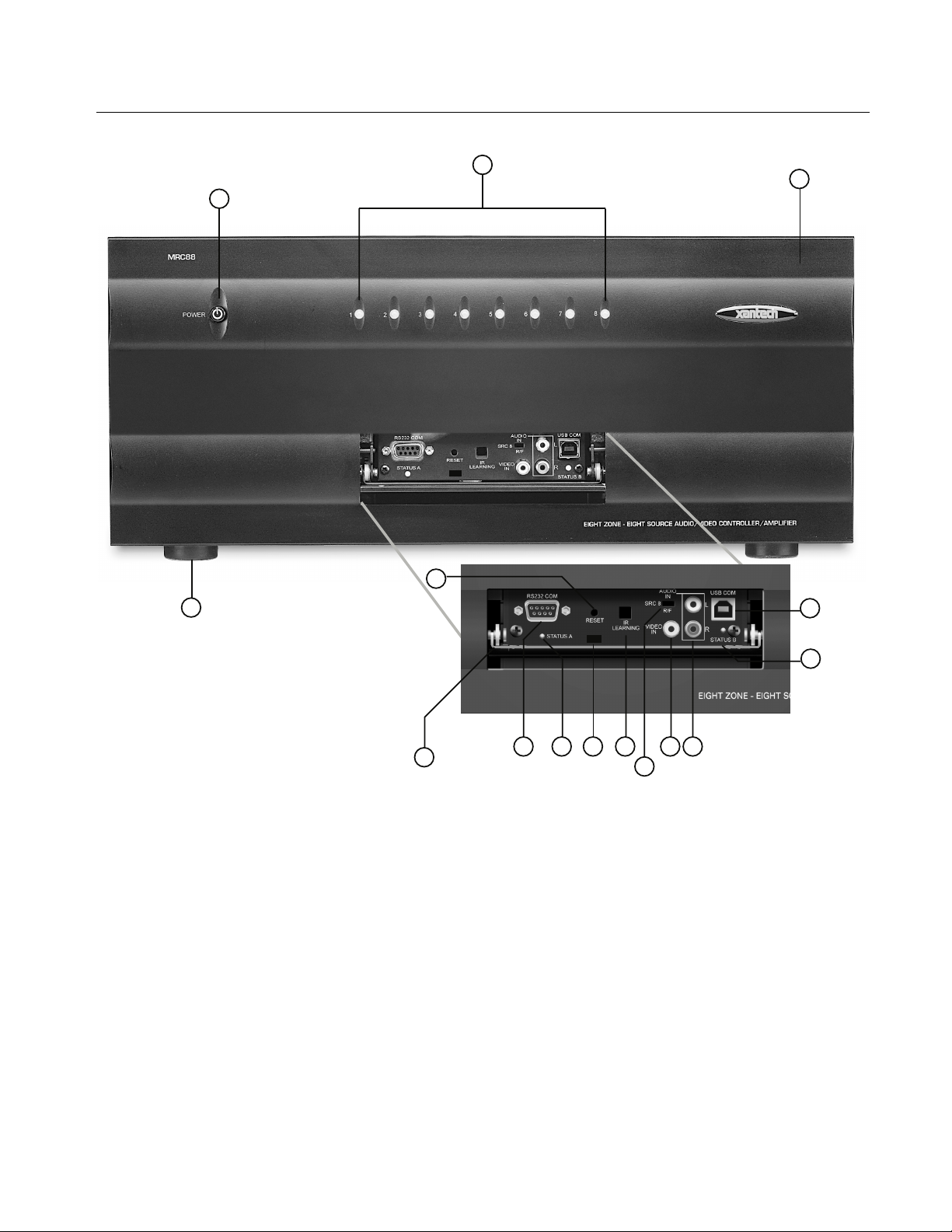
Figure 2 – The Model MRC88 Controller/Amplifier – Front Panel Features and Functions
MRC88 FRONT PANEL FEATURES AND CONNECTIONS:
1. Front Panel.
2. Chassis Feet. Set high enough to provide through-chassis cooling by natural convection.
3. Master AC Line On/Off Switch. Turns AC power On/Off to the entire unit.
4. Power and Status LED Indicators. Eight indicators, one for each Zone, provide the following status
information:
System Status (Power-Up Mode)
a) Slow Orange Blink – indicates general initialization is occurring.
b) Fast Green Blink – indicates that a keypad on the associated zone is currently being initialized.
c) Fast Red Blink – indicates that the master keypad on the associated zone is not responding to
initialization.
d) Fast Orange Blink – indicates that the slave keypad on the associated zone is not responding to
initialization.
e) All Lights Off – initialization is done, system is ready for operation.
© 2003 Xantech Corporation

Page: 14 Model MRC88
Zone Status (Active-Operational Mode)
a) Steady Green – indicates that the Zone is Active (Keypad ON), is not muted and is not within 5 dB of
MAX-V.
b) Steady Red – indicates that the Zone is Active, is not muted and is within 5 dB of MAX-V.
c) Slow Green Blink – indicates that the Zone is in the Active, is muted and is not within 5 dB of MAX-V.
d) Slow Red Blink – indicates that the Zone is Active, is muted and is within 5 dB of MAX-V.
e) Fast Green Blink – indicates that Zone is Active, is being Ramped Up or Down and is not within 5 dB of
MAX-V.
f) Fast Red Blink – indicates that the Zone is Active, is being Ramped Up or Down and is within 5 dB of
MAX-V.
f) Off to indicate that Zone is in Not Active (Keypad OFF).
5. Front Panel Access Door. Push gently on lower half of door to open. Allows access to programming
connections, Level Reset and Front Panel Source 8 A/V Input.
6. Level Reset. Pressing this button twice within 1 second restores all of the Factory Default Settings for all
zones. The Factory Defaults are as follows:
• Mute Off
• Treble and Bass Flat
• Balance Centered
• Z-Adjust Treble and Bass Flat
• Z-Adjust Balance Centered
• Z-Adjust Max-V Cleared
• Z-Adjust Max-On-V Cleared
• Trim Levels Cleared
• IR Code Group set to A8
NOTE: The Control Amp will always return to last set values (plus any unaltered factory defaults) after main
power shut down or after any power interruptions.
7. IR Learning Eye. The IR Eye on the MRC88 Controller front panel allows teaching IR Codes to Dragon
Drop-IR™ via the Control Amp when connected to a PC ‘s com port.
8. RS232 Com Port. DB9 Connector. Used to program the MRC88 Controller from a PC using Dragon DropIR™ Software and for Firmware Upgrades.
9. PROTECT On/Off Switch. Selects between Programming Mode (OFF position) and PROTECT (ON)
position to keep program secure in memory.
10. ST ATUS A Led. Green Activity LED, lights during Program Download from Dragon Drop-IR™ Software,
during IR Learning and for Firmware Upgrades when using the RS232 Port located on the front panel
11. USB Com Port. Used to program the MRC88 Controller from a PC using Dragon Drop-IR™ Software and
for Firmware Upgrades.
12. STATUS B Led. Green Activity LED, lights during Program Download from Dragon Drop-IR™ Software,
during IR Learning and for Firmware Upgrades when using the USB Port located on the front panel.
13. Source 8 AUDIO IN L/R. Front panel Source 8 line level audio input. Gold-plated RCA Jacks for use with
any desired A/V source component such as Camcorder, Video Game or other.
14. Source 8 VIDEO IN. Front panel Source 8 composite video input. Gold-plated RCA Jacks for use with any
desired A/V source component such as Camcorder, Video Game or other.
15. Source 8 Front/Rear Selector Switch. Selects whether the Source 8 Audio/Video inputs will come from
the Front (F) or Rear (R) panel jacks.
© 2003 Xantech Corporation
Model MRC88 Page: 15
27
22
23
20
26
24
30
29
25
19
28
17
18
16
34
21
33
31
32
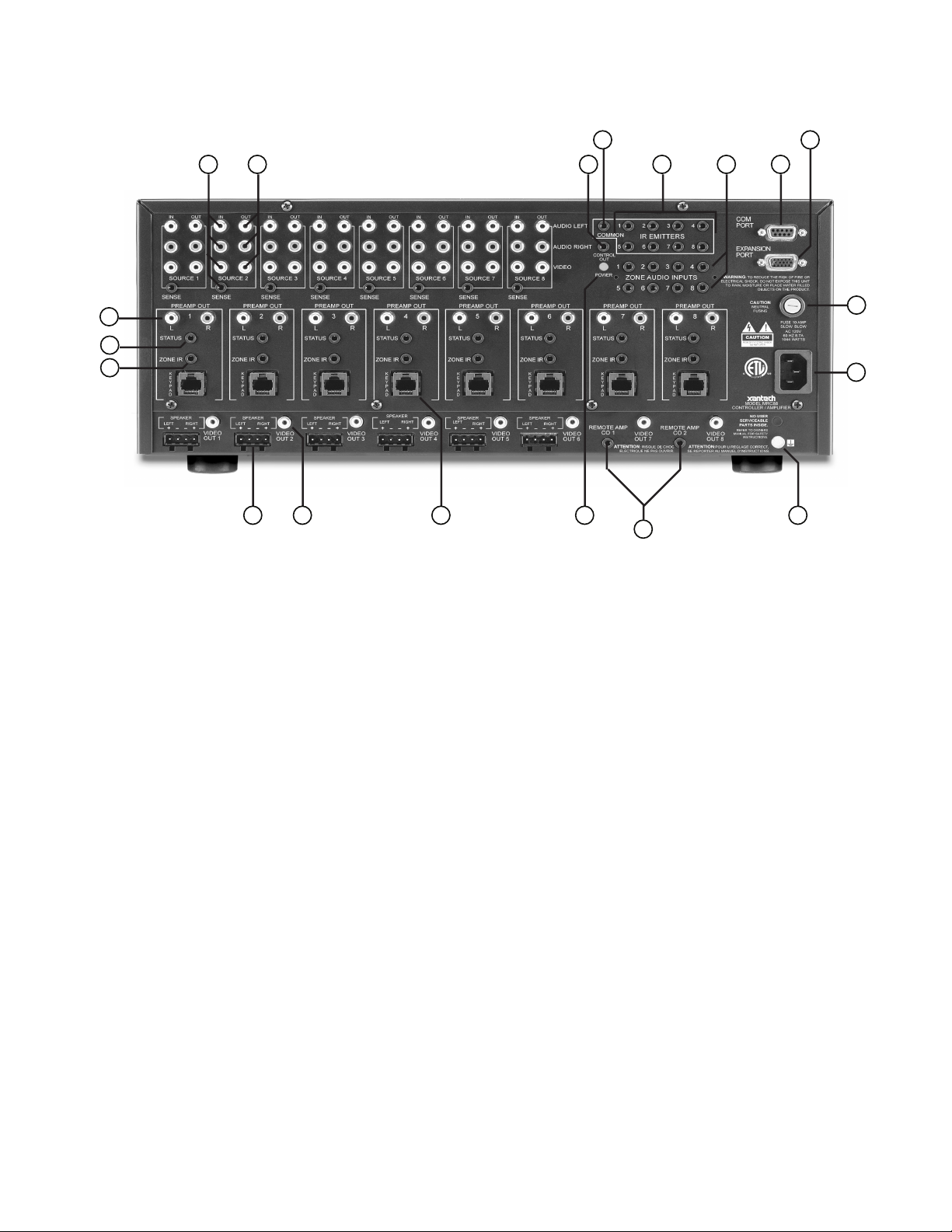
Figure 3 – The Model MRC88 Controller/Amplifier – Rear Panel Connections and Functions
MRC88 REAR PANEL FEATURES AND CONNECTIONS:
16. Keypad Terminals (8). Each Zone has one RJ-45 jack for Keypad Interface. Each connector interfaces the
following: Power (Enough for 1 Primary & up to 4 Secondary Keypads per Zone), RS-485 Data I/O, and IR
Input.
17. Speaker Terminals (6). Plug-in 4-terminal screw type connectors for zones 1 thru 6, permit speaker wire
sizes up to 12AWG.
18. Composite Video Output (8). RCA type connector sends zone selected, source video to the composite
video input on a zone TV or modulator.
19. Status Out (8). Provides a control output of +12 VDC that turns on and off with the zone to drive voltage
sensing relay modules and AC strips.
20. Control Out (8). Mono 3.5mm Mini Phone Jack provides a Control Output that goes high (+12 volts) when
any Zone is first turned ON and goes low (0 volts) when the last Zone is turned OFF. [Tip=+VDC;
Shield=GND]
21. Remote Amp Control Out (CO1 & CO2). Stereo 3.5mm Mini Phone Jack connects to CONTROL IN
jack of Remote Amp PA435X or PA4100X. Provides STANDBY and MUTE Control of remote Amp from
Zone 7 (CO1) and Zone 8 (CO2). [Tip = STANDBY Logic; Ring = MUTE Logic; Shield = GND]
22. Source Component Input Connections (8)
a) Source Audio Inputs. Gold-plated RCA Jacks for Stereo/Dolby Pro line level audio input from source
components.
b) Source Video Inputs. Gold-plated RCA Jacks for composite video input from source components.
c) Sense Inputs. 3.5mm Stereo Mini Phone Jacks for use with the CSM1 MRC88 Current Sense Module.
© 2003 Xantech Corporation

Page: 16 Model MRC88
23. Source Loop-Thru Connections (8).
a) Audio Loop-Thru. Parallel Connection to Audio Inputs for connecting Audio Source to another MRC-
88 in Expanded Mode or to other local devices. This is not an active output.
b) Video Loop-Thru. Buffered Video Connection for connecting Input Video Source to another MRC-88 in
Expanded Mode or to other local devices. NOTE: Since this is a Buffered video connection, this loop-
thru is not active when POWER is removed from the MRC88
24. Zone Audio Inputs (8). 3.5mm Stereo Mini Phone Jack for Zone specific stereo audio Server Inputs. Zone
Audio Inputs override rear panel, Source 1 connection. Allows each of the 8 Zones to have a dedicated
Server Output by selecting Source 1 on keypad.
25. Zone Audio Pre-Amp Out (8). Gold-plated RCA Jacks for connecting Zone Audio Output to an external
amplifier. For use with applications where either more power is required for Zone or passing to a Dolby Pro
compatible receiver for theater quality audio in zone.
26. IR Emitters (1-8). 3.5mm Mono Mini Phone Jacks. These mini jacks are for the connection of IR emitters to
control individually the eight source components. These jacks are “steerable” with Dragon Drop-IR™
Software for IR Routing and Priority Lockout. IR received from a Zone will be routed to the emitter port
corresponding to the Zones active source selection. Can also be configured as 8 common emitter ports
(ADVANCED only) (See: Section 5: Controller Options Programming).
27. IR Emitter (Common). 3.5mm Mono Mini Phone Jacks. Single Common IR Output that can be used to
control devices such as Multi Zone Audio Server, motorized drapery systems, TV lifts and lighting systems
or any other IR controlled component. IR Received from any Zones Keypad will be output the Common
emitter port regardless of source selection.
28. Zone IR Out (8). 3.5mm Mono Mini Phone Jacks. IR received from a Zone will always be passed to the
corresponding Zone IR output. This can be used to control Zone Specific components not located in the
zone.
29. Com Port. DB9 RS232 Control Port allows full control from an external PC component of all Internal
Amplifier Commands of the MRC88 Controller and the ability to trigger programmed IR Macros for control of
devices connected to the Controllers emitter ports. The Com Port can also be used in the reverse to send
ASCII/Hex commands OUT to control an external RS232 device directly from the MRC88 Keypad and/or
handheld remote.
30. Expansion Port. DB15. Allows two MRC88’s to be connected together, via included Expansion Cable, to
provide an 8 Source/16 Zone system with full control between units.
31. User Replaceable Fuse. 10 AMP 250 VAC, Slow Blow Fuse (Domestic version). 5 AMP 250 VAC, TimeLag Fuse (European version).
32. AC Power Input. Standard IEC 3-Conductor AC Line Cord Receptacle for plug-in of a 3-conductor power
line cord.
33. Grounding Screw. “Knurled Screw” provides a means for chassis connection to earth ground or to other
Audio/Video products to aid in the reduction of system noise.
34. Power On/Off LED. This LED indicates the Main Power ON/OFF Condition of the MRC88 Controller.
© 2003 Xantech Corporation
Model MRC88 Page: 17
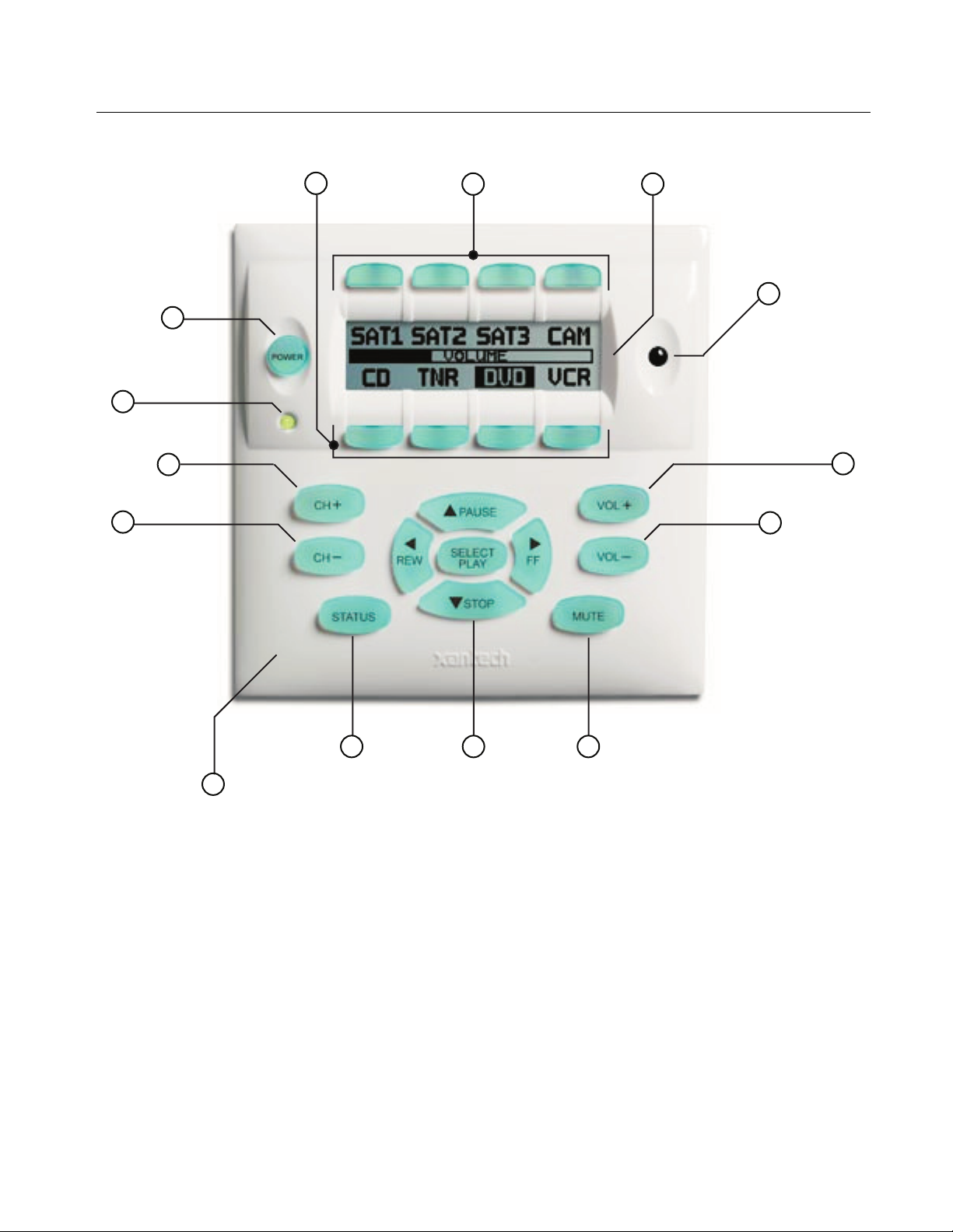
MRC88 KEYPAD FEATURE DESCRIPTIONS
7
2
4
6
5
3
11
12
13
1
14
10
9
Figure 4 – The Model MRC88 Keypad – Front Panel Features and Functions
MRC88 KEYPAD - FRONT FEATURES:
1. MRC88 Keypad.
2. Power. Turns the zone ON and OFF. Can be programmed with IR codes or sequences.
3. IR Sensor. Receives IR from hand-held remotes to control both source components and the MRC88
system. A Programmable Learning Remote such as the Xantech URC2 is recommended for integrating the
IR commands of the MRC88 and source components into a single controller. Compatible with most brands
of remote controls, though some may not be programmable and will therefore only control the source
components.
4. Status Indicator LED. Will indicate zone/system status and will flash as IR is received at the IR Sensor.
These indicators, one for each Keypad, provide the following Information:
a) LED Off = Zone OFF
b) Steady Green = Zone ON
c) Slow Green Blink = Zone MUTE
8
© 2003 Xantech Corporation

Page: 18 Model MRC88
d) Fast Red Blink = IR Sensor INPUT or Keypad OUTPUT
e) Fast Amber Blink = System BUSY
5. LCD Display. When the zone power is ON, the LCD will indicate the selected source, zone volume level,
zone and system status and other system conditions. The display is automatically backlit when any button
is pressed (backlight is programmable via Dragon Drop-IR™ software).
6. Source 1-4 Selector Buttons. Pressing of Source Button selects the corresponding source’s Audio/Video
signal to be played in the Zone of the keypad pressed. Pressing of the Source Button will reverse the
source icon on the LCD Display and sends IR commands programmed to the button (if any) to the
corresponding source and common emitter outputs as well as Zone Emitter port.
7. Source 5-8 Selector Buttons. Pressing of Source Button selects the corresponding source’s Audio/Video
signal to be played in the Zone of the keypad pressed. Pressing of the Source Button will reverse the
source icon on the LCD Display and sends IR commands programmed to the button (if any) to the
corresponding source and common emitter outputs as well as Zone Emitter port
8. Vol
9. Vol
10. Mute. Mutes zone speaker output. Sends IR commands programmed to this button (if any) to the selected
11. CH
12. CH
13. Status. Displays zone and system status. Allows access to Dynamic Zone Linking and Zone EQ/Balance
14. Select/Play, Stop, Pause, Rew, FF. Each send IR commands programmed to these buttons to the
+. Increases zone volume and moves the Volume Bar on the LCD Display to indicate volume level
(non-programmable).
-. Decreases zone volume and moves the Volume Bar on the LCD Display to indicate volume level
(non-programmable).
source emitter, common emitter, and zone emitter outputs.
+. Sends IR commands programmed to this button to the selected source emitter, common emitter,
and zone emitter outputs.
-. Sends IR commands programmed to this button to the selected source emitter, common emitter, and
zone emitter outputs.
settings (non-programmable).
selected source emitter, common emitter, and zone emitter outputs.
© 2003 Xantech Corporation
Model MRC88 Page: 19
JP1
19
17
JP2
22
15
24
18
20
21
23
16
Figure 5 – The Model MRC88 Keypad – Rear Panel Features and Functions
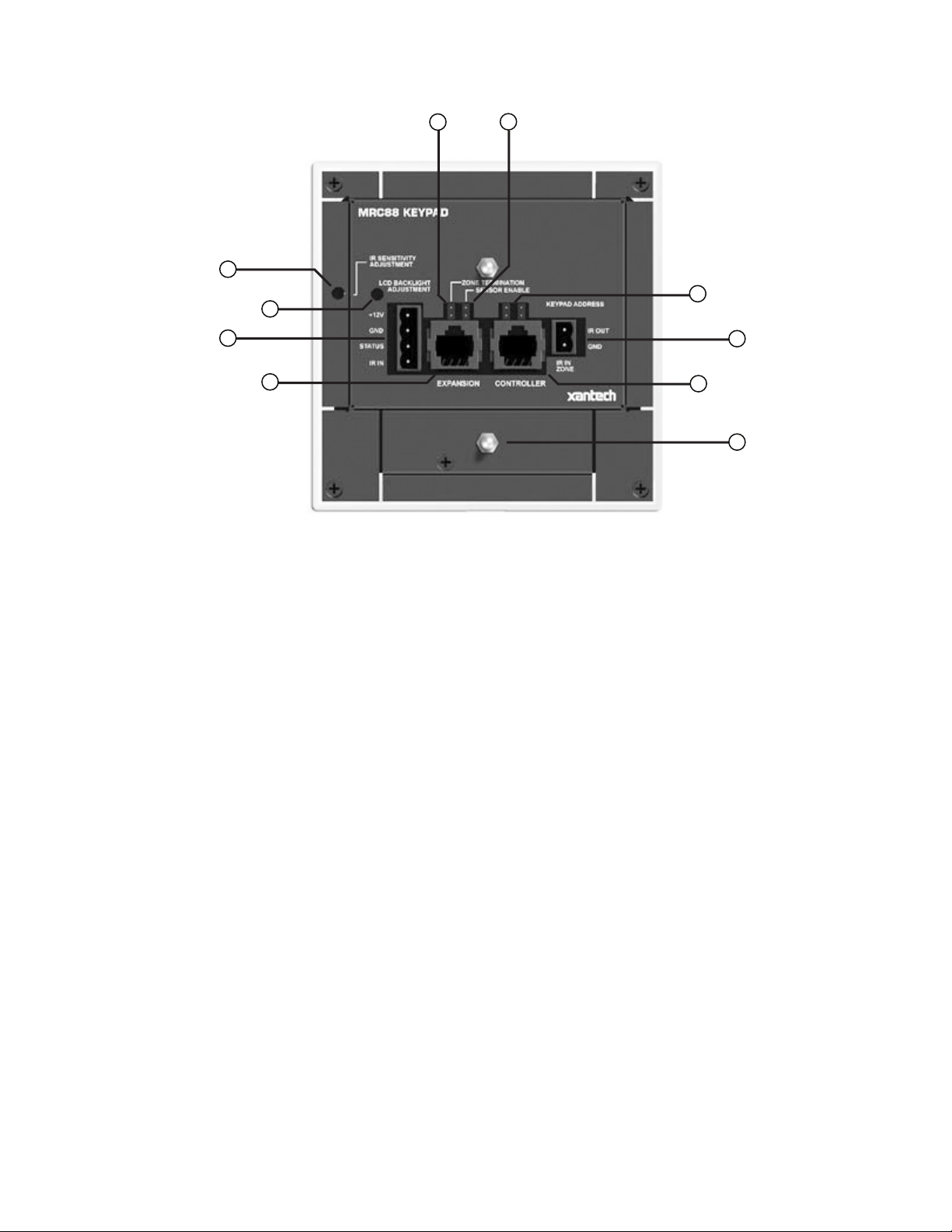
MRC88 KEYPAD - REAR FEATURES AND CONNECTIONS:
15. Controller Terminal. RJ45 Jack. Connects Keypad to zone keypad input on MRC88 Controller via CAT5
cable.
16. Expansion Terminal. RJ45 Jack. Allows keypad to be daisy chained to another keypad for multiple control
locations within a zone. Up to 4 keypads are supported per zone.
17. Keypad Address. Pair of Jumpers. Used to assign Keypad Address. Each Keypad in the zone must have a
unique address (up to 4 keypads in a Zone).
18. Zone Termination. Jumper. Do not remove jumper if there is only one keypad in a zone. If there is more
then one keypad in a zone, remove from all but the last keypad in the daisy chain configuration.
19. Sensor Enable. Jumper. Enables IR sensor on Keypad. Remove when using an external IR receiver.
20. IR Sensitivity Adjustment. Carefully adjust for background light level to prevent false triggering of the IR
circuits. Slowly turn counter-clockwise to reduce sensitivity.
21. LCD Backlight Adjustment. Adjusts brightness of LCD backlight. This adjustment does not affect the
backlight level for the buttons. Slowly turn counter-clockwise to reduce brightness.
22. IR In-Zone. 2-Terminal WECO style socket - Zone IR out for local ‘In-Zone’ emitter out. Used for IR control
of equipment in the same location as the keypad. Any IR generated from within the Zone (or routed to that
zone from another) will be output from the IR IN-Zone connector as well as the Zone IR jack on the rear of
the Controller. This feature is ‘selectable’ via Dragon Drop-IR™ Software.
23. External IR Terminal Block. 4-Terminal WECO style socket – Allows connection of other Xantech IR
Receivers and/or Keypads to be used in conjunction with the MRC88. (i.e. Use Waterpad Keypad in subzone in shower or outdoor zone or Plasma Friendly IR Receiver in place of Keypad IR Receiver).
24. Snap-in Pins. These pins snap into the MRC88 Keypad wall bracket for mounting.
© 2003 Xantech Corporation

Page: 20 Model MRC88
Section 2: Installation & Connections
INSTALLATION
OPERATION: OUT-OF-THE-BOX PRE TEST
(BASIC/ADVANCED/EXPANDED)
The MRC-88 is shipped to operate basic functions ‘Out-Of-The-Box’ without any programming. Simply by
plugging in keypads via standard CAT-5 RJ45 terminated patch cable and powering the controller ‘on’, you can
control Source Selection, Volume Up/Down and speaker Mute capabilities.
Completing the Out-Of-The-Box Pre-Test will verify that all sources and zone components are working properly
to select and distribute audio and video prior to programming with Dragon Drop-IR™. This will ensure that the
unit is indeed functioning correctly ‘prior’ to fixed installation and allow proper troubleshooting procedures if a
problem is encountered. Instructions regarding full programming for specific components and features will
follow.
Note: For ‘EXPANDED’ configuration, test both units individually as outlined below.
Note: For simplicity of test set-up, only one Source Component, one pair of speakers, and one TV/Video
Monitor will be necessary.
For the pre-test, you will need the following:
8-RJ45 Terminated CAT5 cables. (Pre test cables prior to use – See Caution below)
1-Audio/Video Source Component (i.e. VCR, DVD or other) [Will be used to test ALL Source Inputs]
1 Audio/Video RCA Harness (Capable of Audio Left/Right and Video)
1-Pair of speakers with Speaker Cable properly terminated into a 4 conductor WECO Plug [Will be used to
test Speaker outputs]
1-TV or Video Monitor [Will be used to test ALL Video Outputs]
8-283M Blink Emitter
All 8 MRC-88 Keypads
MRC-88 Controller/Amplifier
PA435X Two-Zone Stereo Amplifier (or other)
2 Pair of Stereo RCA Phono cables (for PA435X)
AC Cord
1. Connect MRC88 Controller/Amplifier as shown in Figure 13 to:
a) All MRC88 Keypads via CAT5 Cables
b) Pre Amp Out of Zones 7 and 8 to PA435X Zones 1 and 2 Audio Input
c) Audio/Video Source to SOURCE 1 Audio Left/Right and Video Input terminals
d) TV or Monitor to Video Out 1
e) Speakers to Speaker Output #1
f) All 8 IR emitters to IR Emitter Ports 1 thru 8 (rear connection Item #26)
g) AC Power for MRC88 Controller and Audio/Video Source Component
2. Press “Power On” button on the front of the MRC88 Controller/Amplifier (wait for front panel LED’s to stop
flashing – should be less than 20 seconds).
3. Power ON the Zone 1 TV/monitor and select the appropriate input (on the TV or monitor).
4. Power ON the Source Component and press play.
5. Place the emitter from IR Emitter Port 1 near the front of the Source Components IR Sensor window.
6. Press “POWER” on the Zone 1 Keypad.
7. Select “SRC1” on the Zone 1 MRC88 Keypad.
a) If Source 1 is an Audio/Video component, the video content of the source connected to the Source 1
inputs should be seen on the zone 1 TV/monitor.
© 2003 Xantech Corporation
Model MRC88 Page: 21
b) Press “VOL+” on the Zone 1 Keypad. The Volume bar should move on the Keypad and the audio
content of the source connected to the Source 1 inputs should be should be heard through the Zone 1
speakers.
c) Press “MUTE” on the Zone 1 Keypad. The Zone 1 speakers will mute. Press MUTE again and the
speakers will un-mute. (Pressing VOL+ or VOL- will also un-mute the speakers).
d) Use the source 1 original equipment remote and verify that all source functions operate when aiming
the remote at the Zone 1 Keypad IR sensor.
e) Press “POWER” on the Zone 1 Keypad and verify ALL Status LED’s on the Controller Front Panel are
OFF.
8. Move the Audio/Video Source component to SOURCE 2 Audio Left/Right and Video Input terminals;
Speakers to Speaker Output #2 and the TV/Video Monitor to Video Out #2.
9. Repeat Steps 5 thru 8 for source/Zone 2 thru 8
Note: For Zones 7 & 8 Speakers will be connected to the Speaker A and B output of the PA435x
Caution: Power voltage for the keypad is transmitted along the CAT5 cable! Incorrect wiring on this cable
can destroy the MRC Keypad. Please test the cable connections using a proper CAT5 cable tester
or using a Multimeter to check Pin to Pin continuity and for possible shorts. Using either method, it is
advisable to measure pins 3 and 6 to verify proper voltage with a Multimeter. A 12Vdc measurement
should be read when the positive probe is on pin 6 and the negative probe is on pin 3. See Figure
10.
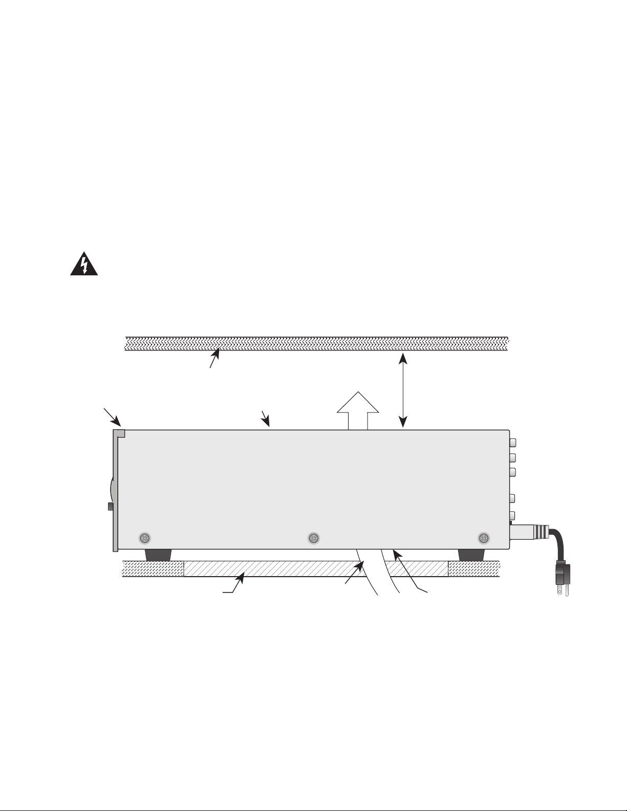
Upper shelf, component, wall, etc.
2-inch spacing
MRC88
Keep perforations on top cover free
of obstructions!
To maximize air flow, route
single large opening in lower shelf.
Convection
Airflow
(minimum)
Keep perforations on bottom
plate free of obstructions.
Figure 6A: MRC88 CTLR mounting
MRC88 CONTROLLER/AMPLIFIER PHYSICAL LOCATION AND MOUNTING
(BASIC/ADVANCED)
When you mount the MRC88 Controller, you should plan its location carefully. Pay close attention to each of
the following factors (refer to Figure 6A above):
1. The amplifier is convection cooled. That is, it depends on the natural free flow of air up through the slot
perforations in the bottom plate, over the internal heat dissipating fins, then out the top cover, for adequate
cooling.
© 2003 Xantech Corporation
Page: 22 Model MRC88
2. If mounted in an equipment cabinet or other confining location, allow at least 2 inches of space above the
top cover. Be sure there are large openings in the shelf below the unit and in the cabinet to allow the entry
of cool air and the escape of warm air.
3. If the cabinet contains other heat generating components or you are using several MRC88's in a large multizone system, you will have to pay even closer attention to adequate ventilation.
4. Do not hesitate to use fans (quiet, boxer type), if necessary, to ensure a constant flow of air through the
MRC88's and the other heat generating components.
5. When mounting in a 19" (483mm) rack, adding a single RU (Rack Unit) spacer above and below the
MRC88 will improve convection in heavy use applications. Note: Rear support may be required.
[One Rack Unit size = 1-3/4" (44.5mm) in height].
6. In multi-zone installations, you will have large bundles of wire and cable to accommodate audio, video and
speaker connections. Be sure to allow enough room for the leads and dress them in such a manner so as
not to block airflow.
7. The MRC88 is designed for mounting on flat horizontal surfaces. When mounting into a 19" rack, use a
proper rack shelf or drawer (i.e. Middle Atlantic or equivalent)
8. Do not remove chassis feet. They are necessary to provide proper ventilation.
NOTE: You should consider some sort of rear support for rack mounted units when used in mobile
applications or when located in seismically active areas.
(EXPANDED)
Place Controllers on separate shelves or provide 2 inches of space between Controllers for ventilation.
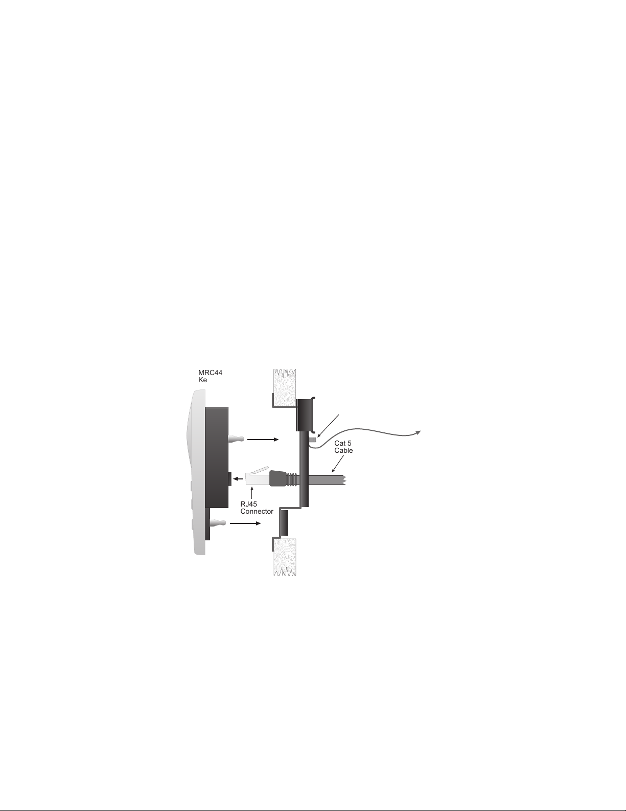
MRC88 KEYPAD PHYSICAL LOCATION AND MOUNTING
(BASIC/ADVANCED/EXPANDED)
MRC44
Keypad
Ground
Lug
To Earth Ground
Cat 5
Cable
RJ45
Connector
Figure 6 - Mounting and Installing the MRC88 Keypad
Keypad mounting for the MRC88 Keypad does not require a junction box. The MRC88 keypad can be mounted
on drywall, lath & plaster, button board or other surfaces covering a hollow wall. Follow these simple
procedures to install the provided MRC88 mounting bracket and keypad:
NOTE: Check local electrical codes. Some areas require a backbox in certain applications. For installations that
require a back-box, see Xantech Part# MRCBOX. The MRC88 keypad will not fit in a standard 2-gang box. The
Xantech MRCBOX must be used in applications that require a backbox.
1. Cutting the hole
a. Mark the desired mounting location for the center of the keypad.
© 2003 Xantech Corporation
Model MRC88 Page: 23
b. Using a level, make proper horizontal and vertical marks on surface to be cut, to properly orient
template.
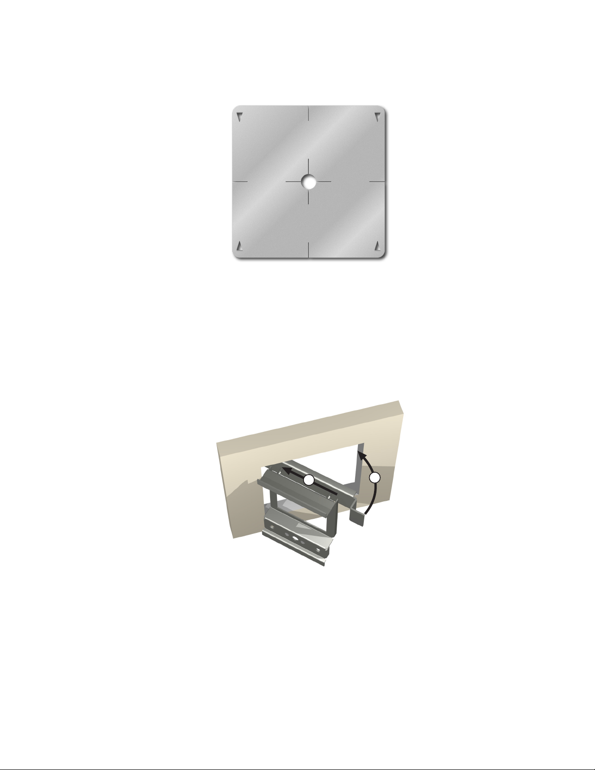
Figure 7 – MRC88 Keypad mounting template
c. Locate the provided template so that the mark is in the center of the hole, which is in the center of the
template.
d. Rotate the template around the center until the template is level.
e. Press or hammer the template in place so that the holding tabs pierce the wall and hold the template in
place.
f. Mark or scribe the outline of the template on the wall.
g. Remove the template and cut a clean hole through the wall along the outline of the template, being sure
that your cut is on the outline. Any cut outside of the outline by more than ¼” may not be covered by the
MRC88 Keypad.
1
2
Figure 8 – Installing the MRC88 Keypad mounting bracket in the wall
2. Installing the Mounting Bracket
a. Attach the ground wire to the ground lug to the rear of the back-bar with the provided green nut, before
beginning the bracket installation process.
NOTE: A ground wire connected to Earth ground is required to protect against static discharge.
b. Orient the Mounting Bracket so the ground lug is on the top portion of the bracket and run the supplied
screws through the top front of the mounting bracket into the back-bar as shown in Figure 6.
Note: Do not tighten screws.
c. Pull the CAT5 cable through the hole in the wall.
d. Pull the CAT5 cable through the hole in the mounting bracket.
© 2003 Xantech Corporation
Page: 24 Model MRC88
e. Slide the left or right side of the back-bar into the wall as shown in Figure 8.
f. Center the mounting bracket in the wall and tighten the screws until the bracket is firmly held in the wall.
Over tightening will distort the bracket and prevent the Keypad from snapping tight against the wall.
Under tightening will cause the Keypad to be loose against the wall.
g. If there is not enough room to slide the keypad in as described above, you can hold the back-bar in
place as you run the screws through the mounting plate and into the back-bar. TIE A LONG STRING
TO THE BACK-BAR so that you can easily retrieve it in case you drop the back-bar into the wall!
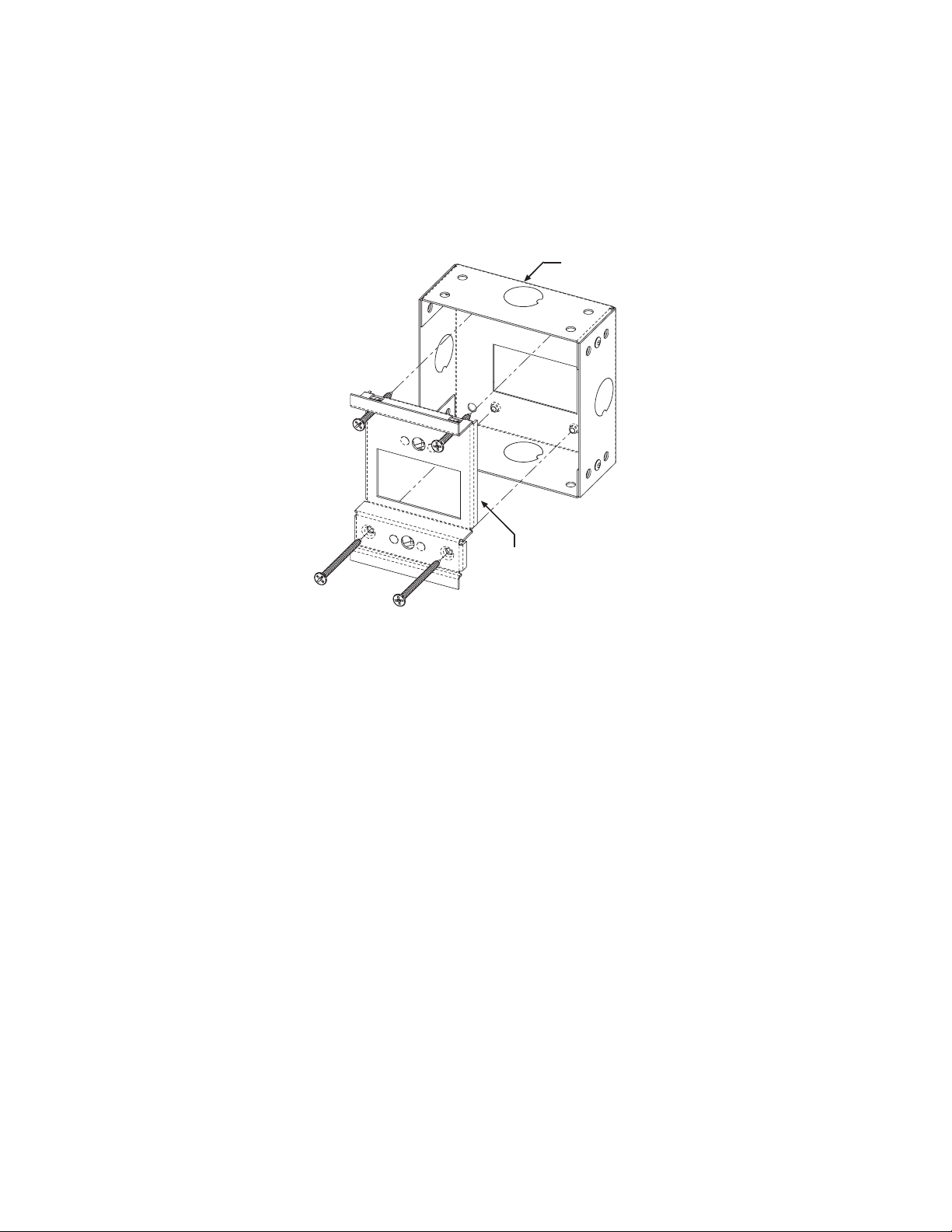
MRCBOX
MRC88 Keypad Mounting Bracket
Figure 8B: Optional Keypad Back-Box for pre-install applications
2-1. MRCBOX (Back-Box) Installation (optional)
a. Position Back-Box so inner rectangle is in a horizontal position. as shown in Figure 8B
b. Affix MRCBOX to Wall Stud at desired height with front of box flush with front of stud (or set back
slightly) as to not interfere with Sheetrock.
c. Attach ground wire to ground lug as described in Step 2a as shown above.
d. Orient the Mounting Bracket so the ground lug is on the top portion of the bracket and using two 1.5”
(38.1mm) self-tapping drywall screws (or sheet metal screws), mount the bracket to the Back Box. For
extra rigidity use two 2” (50.8mm) self-tapping drywall screws (or sheet metal screws) through the
bottom two screw holes.
3. With the Controller/Amplifier turned off, connect the CAT5 cable to the appropriate RJ45 connector, using
Figure 10 as a guide for CAT5 termination.
4. Add or remove jumpers on the rear of the MRC88 keypad-according to Table 1 (Keypad connections).
5. Firmly snap the MRC88 Keypad into the bracket that you have just installed (see Figure 6).
6. Confirm all Keypad operations.
MRC88 KEYPAD REMOVAL
© 2003 Xantech Corporation
Model MRC88 Page: 25
POWER
CH
STATUS
SELECT
REW
1
2
CH
VOL
PAUSE
VOL
PLAY
FF
STOP
MUTE
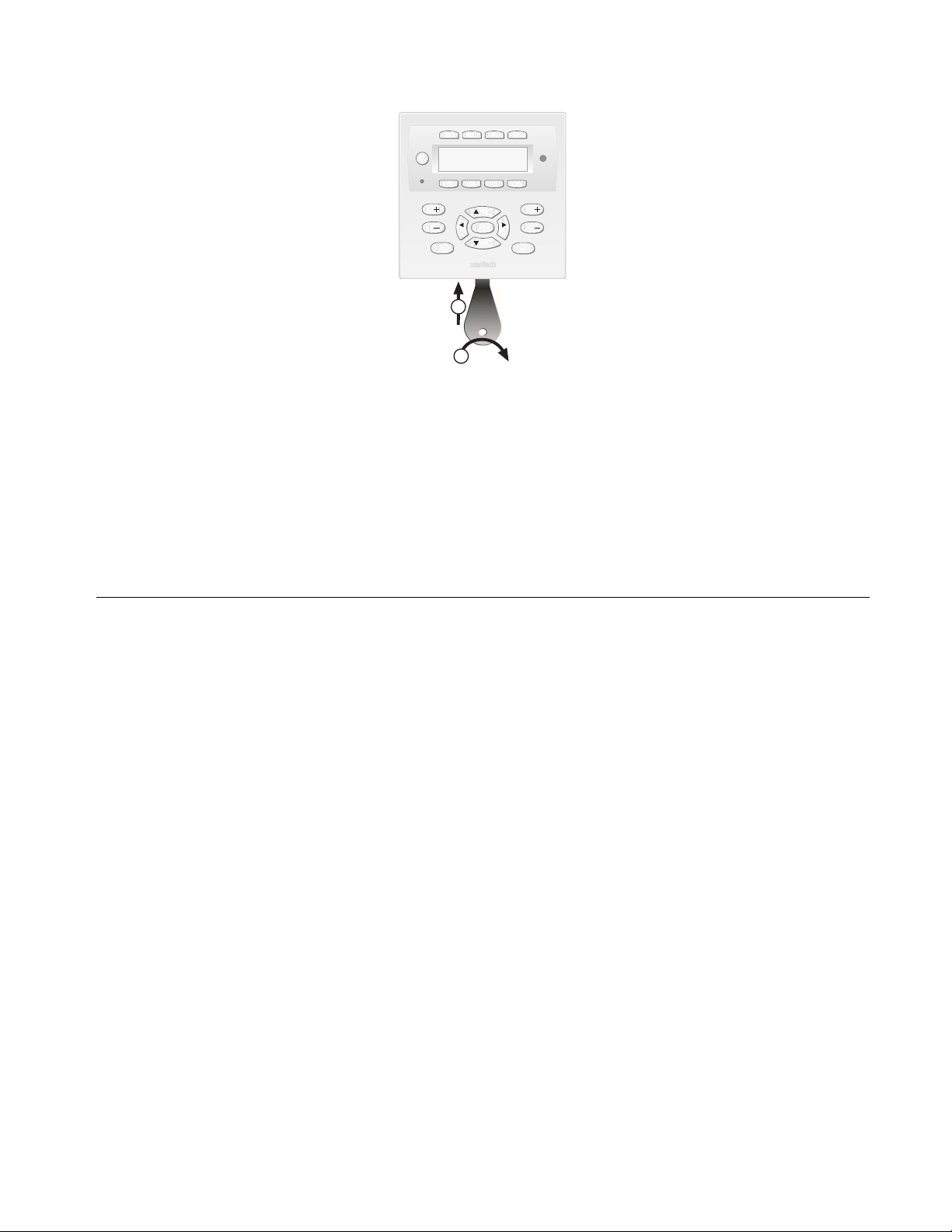
Figure 9 – Removing the MRC88 Keypad from the wall
1. Insert the MRC88 keypad removal tool into the slot at the bottom of the keypad, as shown in Figure 9,
being sure that the tool is inserted so that the “insert to here” line slides under the Keypad. This will reduce
the risk of damage to the Keypad or the wall.
2. Twist the removal tool in either direction until the bottom of the Keypad pulls away from the wall, then
carefully grip the edges of the Keypad with your fingers and pull it off the wall.
NOTE: Since the Keypad snaps into the mounting bracket and there are a large variety of wall textures, the
Keypad may POP OUT or require some additional effort to pull it off the wall, depending on your particular
installation.
CONNECTING THE MRC88 CONTROLLER/AMPLIFIER
When making connections to the MRC88 Controller be sure the power cord is unplugged. Proceed as follows,
referring to Figure 3 and Figure 13 for a typical MRC88 system layout and interconnections:
SOURCE RELATED CONNECTIONS
The following relates to all source related connections to the MRC88 Controller Unit (A/V In/Out, IR Control,
Sense Inputs etc.)
OURCE COMPONENT CONNECTIONS
S
Audio Connections
(BASIC/ADVANCED)
Using good quality RCA-type patch cables connect the LEFT and RIGHT OUTPUT jacks of the source
component (DVD, CD, Satellite receiver, etc.) to the appropriate source AUDIO LEFT and AUDIO RIGHT
INPUT jacks on the MRC88 - Figure 3-(22).. Do this for each source component.
(EXPANDED)
Using good quality RCA-type patch cables connect the source AUDIO LEFT and AUDIO RIGHT OUTPUT
Jacks of the ‘Primary Controller’ - Figure 3-(23). to the corresponding source AUDIO LEFT and AUDIO
RIGHT INPUT jacks on the ‘Secondary Controller’ - Figure 3-(22).
Video Connections
(BASIC/ADVANCED)
Using good quality RCA-type video patch cables connect the VIDEO OUTPUT jacks of the source
component to the VIDEO INPUT jacks on the MRC88 - Figure 3-(22). Do this for each source Component.
(EXPANDED)
© 2003 Xantech Corporation

Page: 26 Model MRC88
Using good quality RCA-type patch cables connect the source VIDEO OUTPUT jacks of the ‘Primary
controller’ [Figure 3-(23)] to the corresponding source VIDEO INPUT jacks on the Secondary Controller -
Figure 3-(22).
ONE AUDIO INPUTS
Z
(ADVANCED)
Use 3.5mm Stereo Mini Jack to Stereo RCA Plug adapter to connect Zone Specific Audio Sources (i.e.
Audio Server or other Zone Specific Audio Component) to the appropriate Zone Audio Input - Figure 3-(24).
The 3.5mm Stereo Jack is wired as follows: Tip = Right Audio Input; Ring = Left Audio Input; Sleeve =
GND. The Zone Audio Input feature is enabled via Dragon Drop-IR™ software in the ADVANCED
configuration only. When enabled, the Zone Audio Input will override the Source 1 Input connected at the
Audio Left/Right RCA Input terminals - Figure 3-(22). Zone Audio Inputs do not support Video.
(EXPANDED)
For Zones 1-8, connect to the Primary Controllers Zone Audio Input as stated above. For Zones 9-16
connect to the Secondary Controllers Zone Audio Input [Figure 3-(24)] as stated above.
CONTROL CONNECT IONS
IR
(BASIC/ADVANCED)
Plug the supplied 283M IR emitters into the appropriate IR Emitter jacks - Figure 3-(26). Be careful to
match the source audio and video connection number on the MRC88 to the IR Emitter jack number. This
will ensure that the IR control signal will be routed to the correct source component. Find the IR sensor
window on the source component and attach the emitter to the components sensor window after removing
the protective paper cover on the flat side of the emitter head. A Common IR jack is also provided for
connection to other auxiliary devices that are not source specific - Figure 3-(27).
(EXPANDED)
Connect emitters to the ‘Primary Controllers’ IR Emitter jacks - Figure 3-(26) as noted above.
Note: The appropriate source IR Emitter of the ‘Secondary Controller’ will also flash regardless of what
zones keypad issues the command but it is recommended to use the emitter jacks of the Primary unit.
ENSE INPUT CONNECTIONS
S
(BASIC/ADVANCED)
The sense input connection will typically be used to sense the power state of a source component using the
Xantech CSM1 Current Sense Module (optional). Plug the 3.5mm mini plug from the CSM1 into the
appropriate sense jack – Figure 3-(22). Be careful to match the source audio and video connection number
on the MRC88 to the appropriate sense jack number. The CSM1 plugs into an AC power source. The
component power cord plugs into the CSM1. (Refer to instructions included with the CSM1 unit).
CSM1 Threshold Adjustments
a. First, make sure the 3.5mm mini-plug is plugged into the appropriate sense jack on the MRC44 and that
the MRC44 is powered ON. (The CSM1 gets low-voltage DC power from the MRC44 – not from the AC
line. See Figure 2-Top for mini-jack pin out )
b. Select the correct position of the RANGE slider switch – the HI position is for devices with a high
current draw when ON, the LO position is for devices with a low current draw when ON (based upon the
lowest current draw state of the component when ON).
c. Manually turn the component ON.
d. Using a small (1/8” wide) blade screwdriver, rotate the current control to the full CLOCKWISE position
(LO CURRENT).
e. Rotate the control COUNTER-CLOCKWISE (towards the HI CURRENT position) until the Threshold
Adjustment LED goes OFF.
f. Turn the component OFF (Standby Mode).
g. Rotate the control CLOCKWISE until the Threshold Adjustment just goes ON.
h. Set the control to a point midway between these two settings. This should be the correct setting.
NOTE 1: If you have trouble with the threshold adjustment correctly detecting the ON and OFF states of
the component, try changing the RANGE slider to the opposite position and then try the adjustment again.
NOTE 2: If the Threshold Adjustment LED does not go ON and OFF with the component power, make
minor adjustments to the threshold adjust until the LED is in proper sync.
© 2003 Xantech Corporation

Model MRC88 Page: 27
NOTE 3: Program IR commands for the MRC44 Controller current sensing as described in the MRC44
Installation Instructions, “PROGRAMMING SENSE CODES”.
(EXPANDED)
Connect CSM1’s as described above to the Primary Controller. Sense inputs are not available on the
Secondary Controller.
ZONE RELATED WIRING CONNECTIONS
In typical applications, each zone will have at least one MRC88 Keypad and a pair of stereo speakers. In
those zones with both audio and video, at least one video monitor or television will also be used. In order to
make these connections, the minimum requirement is home runs of one CAT5 cable for each zone’s
keypad(s), two pairs of 12-18AWG wire for each pair of speakers, and one coaxial cable for a TV or monitor
from each zone to the MRC88 Controller/Amplifier location.
PEAK ER CONNECT IONS
S
(BASIC/ADVANCED/EXPANDED)
1. Using good quality speaker wire, connect the individual speaker leads to the 4-terminal "SPEAKER"
connectors on the MRC88 as shown in Figure 3-(22).
2. The MRC88 Speaker Terminals (amplifier outputs) are 4-Ohm safe. Make sure the combined
impedance presented to the speaker terminals by the speakers (or any combination of speakers) is 4Ohm minimum.
3. Be sure to observe correct polarity by connecting the "+" and "–" terminal from each channel on the
MRC88 to the corresponding "+" and "–" terminals on each speaker. This will ensure proper "phasing"
(See Step 6). Since the connectors are removable, you may unplug them for ease of lead assembly.
4. As a rule of thumb, use 18 gauge speaker wire for speaker runs up to 30' (9m), 16 gauge up to 70'
(21m), and 14 gauge up to 150' (39m). The 4-terminal connectors accept wire sizes up to 12-gauge
max.
5. Strip the insulation back about 1/4" (6mm) and twist the strands on each lead to prevent fraying.
6. Speaker Phasing: To obtain stable imaging and full bass response, it is imperative that stereo
speakers be connected "in phase" with each other. You can verify this as follows:
a) If the "+" (positive) and "–" (negative) terminals on your speakers are correctly marked, and visible,
and you have wired the system with the positive connector on the rear of the MRC88
Controller/Amplifier connected to the positive connector on the speaker and the negative connector
on the rear of the MRC88 Controller/Amplifier connected to the negative connector on the speaker,
then the system will be "in phase". No further action is required. Most manufacturers identify the
positive terminal with a red binding post, a "+" sign, or a red dot.
b) If you are unsure of the markings, you can verify the phasing. Using a mono sound source, such as
AM radio, alternately reverse the leads to one of the speakers. Pick the connection that delivers a
solid center image between the speakers as well as best bass response.
CAUTION: After lead ends are inserted and the screws tightened down, be sure there are no free
strands that could cause shorting!
© 2003 Xantech Corporation
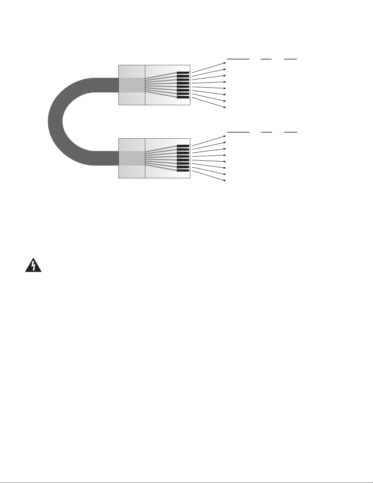
Page: 28 Model MRC88
RJ45 Connector at
Controller/Amplifier
Wire Color Pin # Signal
white/orange 1 485 +
orange 2 485 white/green 3 12V RET
blue 4 IR RET
white/blue 5 IR
green 6 +12V
white/brown 7 Attn. 485
brown 8 IR Loop Back
Cat 5
Cable
Figure 10 - CAT5 Pin Assignments (per EIA/TIA 568B) Pinned 1:1
MRC88
(BASIC/ADVANCED/EXPANDED)
The MRC88 ‘Pin-to-Pin’ CAT5 cabling that can be purchased pre-fabricated at fixed lengths or self-assembled
to custom lengths. The color-coded wiring standard is EIA/TIA 568B as shown in Figure 10. The plastic
connector on the end of the CAT5 wire is “registered jack” RJ45.
1. See Figure 10 for proper termination of the CAT5 cables to the RJ45 connectors.
2. Connect the zone keypad to the appropriate zone Keypad connector on the rear of the MRC88
V
(BASIC/ADVANCED/EXPANDED)
Composite Video
1. When running composite video to a TV or monitor, use RG-6 coaxial or RG-59 quadshield cable with
Modulated Video
3. When modulating the zone video output and using the RF/ANT input to a television, connect the VIDEO
S
KEYPAD CAT5 CABLE CONNECTIONS AT THE MRC88 CONTROLLER/AMPLIFIER
Controller/Amplifier – Figure 3-(16).
Caution:
the MRC Keypad! Be sure to test cable for proper connections before making connections.
IDEO CONNECT IONS
Power voltage for the keypad is transmitted along this cable! Incorrect wiring on this cable can destroy
RCA type phono plugs on each end. This connection can be run up to 150 feet, as this is a buffered
video output from the MRC88 Controller/Amplifier.
2. Connect the zone video cable to the appropriate zone video jack on the rear of the MRC88 Controller/
Amplifier – Figure 3-(18).
OUTPUT from the MRC88 Controller – Figure 3-(18), to the VIDEO INPUT of a Modulator, using high
quality RCA type video patch cords. Use RG-6 coaxial cable with "F" connectors on each end to
connect the Modulator, to the RF/ANT IN on the room TV.
TATUS CONNECTIONS AND COMMON CONTROL OUT
Status
(BASIC/ADVANCED/EXPANDED)
Each zone has a Status Output –Figure 3-(19), that provides a control output of +12 VDC, 50mA that turns
ON and OFF with the zone ON/OFF condition. ON = +12VDC, OFF = 0VDC. Using a 3.5mm mono mini
phone connector, this control can be used to close a relay, such as a Xantech CC12, to raise a TV lift or
drop a projection screen automatically when a zone is turned ON. Connect one end of the 3.5mm Mono
RJ45 Connector
at Keypad
Wire Color Pin # Signal
white/orange 1 485 +
orange 2 485 white/green 3 12V RET
blue 4 IR RET
white/blue 5 IR
green 6 +12V
white/brown 7 Attn. 485
brown 8 IR Loop Back
© 2003 Xantech Corporation

Model MRC88 Page: 29
Mini jack to the appropriate zone Status connector on the rear of the MRC88 Controller/Amplifier and the
other end to the device to control. Tip=Control Voltage; Sleeve=GND
Control Out
(BASIC/ADVANCED)
A single Common Control Output is provided on the rear of the MRC88 Controller/Amplifier –Figure 3-(20).
When the Common Control Output is High (+12 volts, 50 mA), this indicates that ‘at least’ one zone is
powered ON. When the Common Control Output is Low (0 volts), this indicates that ‘all’ zones are OFF.
Using a 3.5mm mono mini phone connector, this control can be used to close relays (Xantech CC12) or
turn on an AC outlet (Xantech AC1, AC2) for activity common to the system. Connect one end of the 3.5mm
Mono Mini jack and the other end to the device to control. Tip=Control Voltage; Sleeve=GND
(EXPANDED)
When at least one zone on either the PRIMARY or SECONDARY controller is turned ON, the Control Out
on the PRIMARY Controller is High (+12VDC). The Control Out on the SECONDARY Controller is inactive
in EXPANDED mode.
REAMP OUT
P
(BASIC/ADVANCED/EXPANDED)
Each zone has a Preamp Out to send ‘zone selected’ audio to another amplifier such as the Xantech
PA435x or PA4100x. This may be desired for feeding a sub-zone on a separate amplifier, zones that
require more than 35W, or for sending audio to another amplifier with Dolby™ surround decoding for
‘theater quality’ audio in the zone.
Using good quality RCA-type patch cables, connect the Preamp Out, Left(L) and Right(R) connectors –
Figure 3-(25), to the desired external amplifiers Audio Left and Right Input connectors.
AND CO2 (ZONES 7 & 8)
CO1
(BASIC/ADVANCED/EXPANDED)
Zones 7 and 8 have a Remote Mute/Standby output for interfacing and controlling a Xantech PA435X
(included) or PA4100X amplifier. The control is provided via a Stereo Mini Jack with the TIP controlling
STANDBY logic (Standby Power On = +12 volts, Standby Power Off = 0 volts) and the RING controlling
MUTE logic (Mute = +12 volts, Un-Mute = 0 volts).
Using a 3.5mm Stereo Mini Jack to 3.5mm Stereo Mini Jack cable, plug one end into the CO1 (or CO2)
output jack on the rear of the MRC88 Controller/Amplifier – Figure 3-(21) and the other end into the
corresponding jack labeled CO1 (or CO2) on the PA435X or PA4100X amplifier.
NOTE: Be sure to set the Control In (CI) switch to ON located on the rear of the PA435X or PA4100X
amplifier.
ONE IR
Z
(BASIC/ADVANCED/EXPANDED)
Using Xantech Emitters (282M, 283M,284M, or 286M), plug the 3.5mm Mono Mini jack into the appropriate
zones Zone IR connector – Figure 3-(28). Affix the mouse emitter side to the desired zone related
component you wish to control. If more than one device needs to be controlled, use a mono mini to
stripped-ends wire (PN#6015900) wired to a Xantech 791-44 Amplified Connecting block. Any IR generated
in the zone (either from MRC-88 Keypad, IR received at the Keypad, or routed from another zone
(ADVANCED only)) will be passed to this emitter port.
POWER CONNECTIONS
AC
(BASIC/ADVANCED/EXPANDED)
Use the supplied power cable and plug into a power source capable of delivering the rated amps shown in
the specification section of this manual.
CONNECTIONS AT THE ZONE LOCATION
(BASIC/ADVANCED/EXPANDED)
© 2003 Xantech Corporation

Page: 30 Model MRC88
EYPAD CONNECTIONS AND JUMPER SETTINGS
K
Single Keypad CAT5 Connections
1. Refer to Figure 10 for proper termination at the zone-end of the CAT5 cable.
2. Set Keypad Address jumper configuration on the rear of the keypad – Figure 5-(17) according to Table
1 below.
2. Connect the CAT5 cable from the MRC88 Controller/Amplifier into the RJ45 jack marked “Controller” on
the rear of the MRC88 keypad.
Caution:
destroy the MRC Keypad! Be sure to test cable for proper connections before making connections.
Power voltage for the keypad is transmitted along this cable! Incorrect wiring on this cable can
Multiple Keypad Connections
1. For a second keypad in the same zone, terminate the CAT5 cable in the same way as shown in Figure
10.
2. Connect the CAT5 coming from the MRC88 Controller to the “CONTROLLER” jack on the Primary
Keypad. Plug a CAT5 cable into the “EXPANSION” jack on the Primary Keypad and connect it to the
“CONTROLLER” jack on the Secondary Keypad. Repeat for all keypads in zone (up to a total of 4
Keypads) Set the Address jumpers on the rear of the keypad – Figure 5-(17) according to Table 1
below.
© 2003 Xantech Corporation
 Loading...