


S1A-T1
WTE S1A-T1, S1A-T3, S1B-T1, S1B-T3, S1D-T1 Datasheet
...
WTE
POWER SEM ICOND UCTOR S
S1A – S1M
1.0A SURFACE MOUNT GLASS PASSIVATED RECTIFIER
Features
!
Glass Passivated Die Construction
!
Ideally Suited for Automatic Assembly B
!
Low Forward Voltage Drop
!
Surge Overload Rating to 30A Peak D
!
Low Power Loss A
!
Built-in Strain Relief F
!
Plastic Case Material has UL Flammability
Classification Rating 94V-O C H G
E
Mechanical Data
!
Case: Molded Plastic
!
Terminals: Solder Plated, Solderable
per MIL-STD-750, Method 2026
!
Polarity: Cathode Band or Cathode Notch
!
Marking: Type Number
!
Weight: 0.093 grams (approx.)
Maximum Ratings and Electrical Characteristics
Characteristic Symbol S1A S1B S1D S1G S1J S1K S1M Unit
Peak Repetitive Reverse Voltage
Working Peak Reverse Voltage
DC Blocking Voltage
RMS Reverse Voltage V
Average Rectified Output Current @TL = 100°C I
RRM
V
RWM
V
R
V
R(RMS)
O
50 100 200 400 600 800 1000 V
35 70 140 280 420 560 700 V
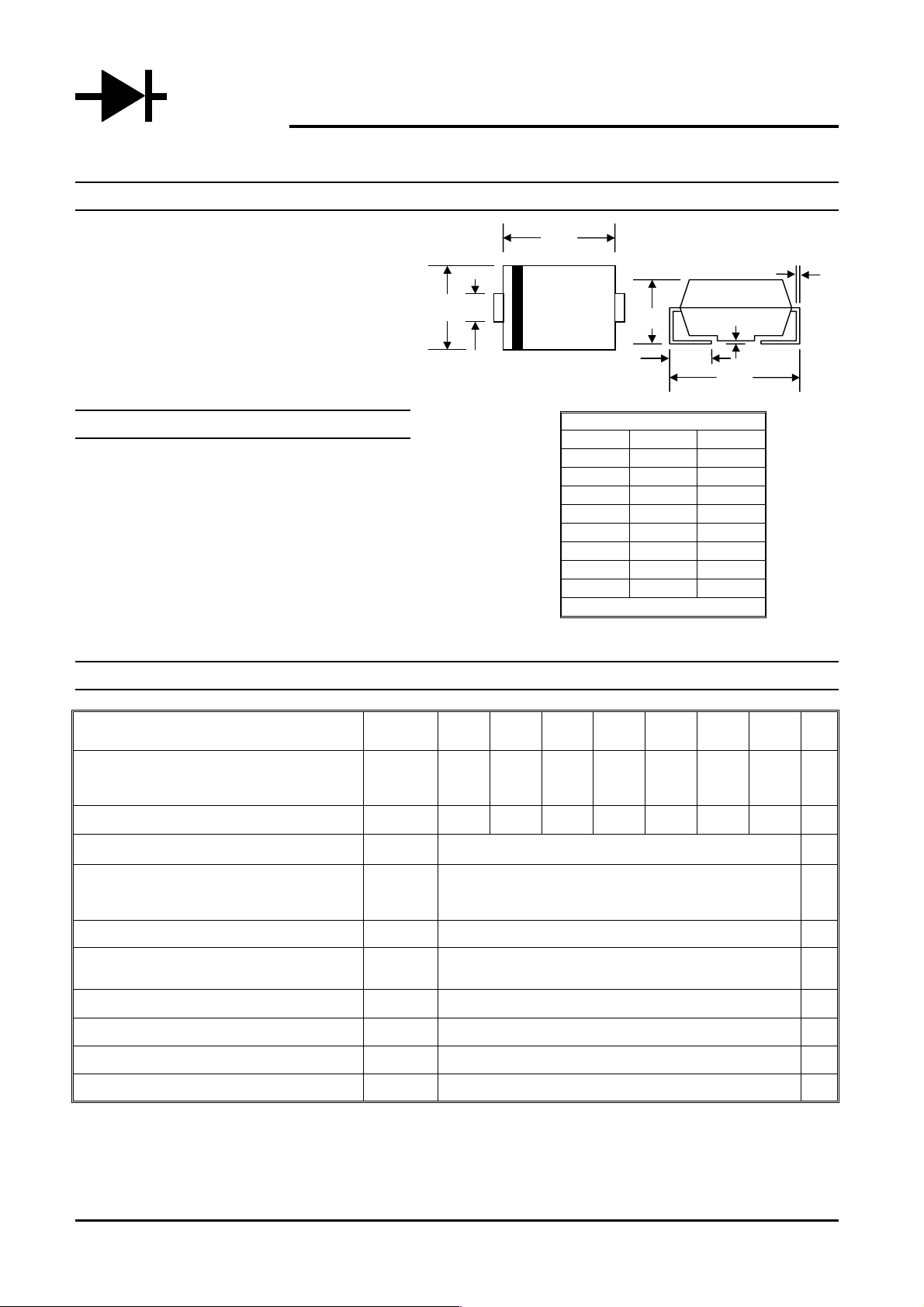
SMB/DO-214AA
Dim Min Max
A
B
C
D
E
F
G
H
All Dimensions in mm
@TA=25°C unless otherwise specified
3.30 3.94
4.06 4.70
1.91 2.11
0.152 0.305
5.08 5.59
2.13 2.44
0.051 0.203
0.76 1.27
1.0 A
Non-Repetitive Peak Forward Surge Current
8.3ms Single half sine-wave superimposed on
rated load (JEDEC Method)
Forward Voltage @IF = 1.0A V
Peak Reverse Current @TA = 25°C
At Rated DC Blocking Voltage @T
Reverse Recovery Time (Note 1) t
Typical Junction Capacitance (Note 2) C
Typical Thermal Resistance (Note 3) R
Operating and Storage Temperature Range T
Note: 1. Measured with IF = 0.5A, IR = 1.0A, Irr = 0.25A,
2. Measured at 1.0 MHz and applied reverse voltage of 4.0 V DC.
3. Mounted on P.C. Board with 8.0m m
S1A – S1M 1 of 3 © 2002 Won-Top Electronics
= 125°C
A
2
land area.
FSM
I
FM
RM
I
rr
j
JL
j, TSTG
30 A
1.10 V
5.0
200
2.5 µS
15 pF
30 K/W
-65 to +175 °C
µA
 Loading...