


REAR DISCHARGE |
MANUAL |
|
|
MOWERS |
|
|
RD6000-2 |
|
|
RD7200-2 |
|
|
RD8400-2 |
|
|
|
|
MAN0180 |
Tested. Proven. Unbeatable. |
OPERATOR'S |
4/28/2006Rev. |
||

TO THE DEALER:
Assembly and proper installation of this product is the responsibility of the Woods® dealer. Read manual instructions and safety rules. Make sure all items on the Dealer’s Pre-Delivery and Delivery Check Lists in the Operator’s Manual are completed before releasing equipment to the owner.
The dealer must complete the Product Registration included with the Operator’s Manual. The customer must sign the registration which certifies that all Dealer Check List items have been completed. The dealer is to return the prepaid postage portion to Woods, give one copy to the customer, and retain one copy. Failure to complete and return this card does not diminish customer’s warranty rights.
TO THE OWNER:
Read this manual before operating your Woods equipment. The information presented will prepare you to do a better and safer job. Keep this manual handy for ready reference. Require all operators to read this manual carefully and become acquainted with all adjustment and operating procedures before attempting to operate. Replacement manuals can be obtained from your dealer. To locate your nearest dealer, check the Dealer Locator at www.WoodsEquipment.com, or in the United States and Canada call 1-800-319-6637.
The equipment you have purchased has been carefully engineered and manufactured to provide dependable and satisfactory use. Like all mechanical products, it will require cleaning and upkeep. Lubricate the unit as specified. Observe all safety information in this manual and safety decals on the equipment.
For service, your authorized Woods dealer has trained mechanics, genuine Woods service parts, and the necessary tools and equipment to handle all your needs.
Use only genuine Woods service parts. Substitute parts will void the warranty and may not meet standards required for safe and satisfactory operation. Record the model number and serial number of your equipment in the spaces provided:
Model: _______________________________ |
Date of Purchase: _____________________ |
Serial Number: (see Safety Decal section for location) ____________________________________
Provide this information to your dealer to obtain correct repair parts.
Throughout this manual, the term IMPORTANT is used to indicate that failure to observe can cause damage to equipment. The terms CAUTION, WARNING, and DANGER are used in conjunction with the Safety-Alert Symbol (a triangle with an exclamation mark) to indicate the degree of hazard for items of personal safety.

 DANGER
 WARNING
 CAUTION
IMPORTANT NOTE
This Safety-Alert Symbol indicates a hazard and means ATTENTION! BECOME ALERT! YOUR SAFETY IS INVOLVED!
Indicates an imminently hazardous situation that, if not avoided, will result in death or serious injury.
Indicates a potentially hazardous situation that, if not avoided, could result in death or serious injury, and includes hazards that are exposed when guards are removed.
Indicates a potentially hazardous situation that, if not avoided, may result in minor or moderate injury.
Indicates that failure to observe can cause damage to equipment.
Indicates helpful information.
|
|
|
|
ii Introduction |
Gen’l (Rev. 5/23/2005) |
||
|
|
|
|

TABLE OF CONTENTS
INTRODUCTION . . . . . . . . . . . . . . . . . . . . . . . . . . . . . . . . .Inside Front Cover SPECIFICATIONS. . . . . . . . . . . . . . . . . . . . . . . . . . . . . . . . . . . . . . . . . . . . . 2 GENERAL INFORMATION . . . . . . . . . . . . . . . . . . . . . . . . . . . . . . . . . . . . . . 2 SAFETY RULES . . . . . . . . . . . . . . . . . . . . . . . . . . . . . . . . . . . . . . . . . . . . . . 5 SAFETY DECALS . . . . . . . . . . . . . . . . . . . . . . . . . . . . . . . . . . . . . . . . . . . . . 6 OPERATION . . . . . . . . . . . . . . . . . . . . . . . . . . . . . . . . . . . . . . . . . . . . . . . . . 8 OWNER SERVICE . . . . . . . . . . . . . . . . . . . . . . . . . . . . . . . . . . . . . . . . . . . 14 TROUBLE SHOOTING . . . . . . . . . . . . . . . . . . . . . . . . . . . . . . . . . . . . . . . . 18 DEALER SERVICE . . . . . . . . . . . . . . . . . . . . . . . . . . . . . . . . . . . . . . . . . . . 20 ASSEMBLY . . . . . . . . . . . . . . . . . . . . . . . . . . . . . . . . . . . . . . . . . . . . . . . . . 28 DEALER CHECK LIST . . . . . . . . . . . . . . . . . . . . . . . . . . . . . . . . . . . . . . . . 32 PARTS LISTS . . . . . . . . . . . . . . . . . . . . . . . . . . . . . . . . . . . . . . . . . . . . . . . 33 BOLT TORQUE CHART . . . . . . . . . . . . . . . . . . . . . . . . . . . . . . . . . . . . . . . 41 BOLT SIZE CHART & ABBREVIATIONS . . . . . . . . . . . . . . . . . . . . . . . . . . 42 INDEX . . . . . . . . . . . . . . . . . . . . . . . . . . . . . . . . . . . . . . . . . . . . . . . . . . . . . 43 PRODUCT WARRANTY . . . . . . . . . . . . . . . . . . . . . . . . . . . . . . . . . . . . . . . 44 REPLACEMENT PARTS WARRANTY . . . . . . . . . . . . . . . . Inside Back Cover
!LEA EL INSTRUCTIVO!
Si no lee Ingles, pida ayuda a alguien que si lo lea para que le traduzca las medidas de seguridad.
(Rev. 4/28/2006) MAN0180 (Rev. 1/7/2005)
Introduction 1
SPECIFICATIONS
|
RD6000-2 |
RD7200-2 |
RD8400-2 |
3-Point Hitch |
Category 1 |
Category 1 |
Category 1 |
Cutting Width |
60" |
72" |
84" |
Cutting Height Range |
1" - 5-1/2" |
1" - 5-1/2" |
1" - 4-1/4" |
Operating Weight with |
|
|
|
Chain Shielding |
605 lbs |
671 lbs |
770 lbs |
Blade Speed (feet per minute) |
16,950 |
16,800 |
16,700 |
Blade Speed (RPM) |
3,083 |
2,570 |
2,179 |
2 Introduction |
MAN0180 (Rev. 1/7/2005) |
|
|

SAFETY RULES
ATTENTION! BECOME ALERT! YOUR SAFETY IS INVOLVED!
Safety is a primary concern in the design and manufacture of our products. Unfortunately, our efforts to provide safe equipment can be wiped out by an operator’s single careless act.
In addition to the design and configuration of equipment, hazard control and accident prevention are dependent upon the awareness, concern, judgement, and proper training of personnel involved in the operation, transport, maintenance and storage of equipment.
It has been said “The best safety device is an informed, careful operator.” We ask you to be that kind of operator.
TRAINING
Safety instructions are important! Read all attachment and power unit manuals; follow all safety rules and safety decal information. (Replacement manuals and safety decals are available from your dealer. To locate your nearest dealer, check the Dealer Locator at www.WoodsEquipment.com, or in the United States and Canada call 1-800-319- 6637.) Failure to follow instructions or safety rules can result in serious injury or death.
Know your controls and how to stop engine and attachment quickly in an emergency.
If you do not understand any part of this manual and need assistance, see your dealer.
Operators must be instructed in and be capable of the safe operation of the equipment, its attachments, and all controls. Do not allow anyone to operate this equipment without proper instructions.
Never allow children or untrained persons to operate equipment.
PREPARATION
Check that all hardware is properly installed. Always tighten to torque chart specifications unless instructed otherwise in this manual.
Always wear relatively tight and belted clothing to avoid getting caught in moving parts. Wear sturdy, rough-soled work shoes and protective equipment for eyes, hair, hands, hearing, and head; and respirator or filter mask where appropriate.
Make sure attachment is properly secured, adjusted, and in good operating condition.
Make sure spring-activated locking pin or collar slides freely and is seated firmly in tractor PTO spline groove.
Make sure driveline shield tether chains are attached to the tractor and equipment as shown in this manual. Replace if damaged or broken. Check that driveline guards rotate freely on driveline before putting equipment into service.
Before starting power unit, check all equipment driveline guards for damage. Replace any damaged guards. Make sure all guards rotate freely on all drivelines. If guards do not rotate freely on drivelines, repair and replace bearings before putting equipment into service.
Power unit must be equipped with ROPS or ROPS cab and seat belt. Keep seat belt securely fastened. Falling off power unit can result in death from being run over or crushed. Keep foldable ROPS system in “locked up” position at all times.
Power unit must be equipped with ROPS or ROPS cab and seat belt. Keep seat belt securely fastened. Falling off power unit can result in death from being run over or crushed. Keep foldable ROPS system in “locked up” position at all times.
Remove accumulated debris from this equipment, power unit, and engine to avoid fire hazard.
Make sure all safety decals are installed. Replace if damaged. (See Safety Decals section for location.)
Make sure shields and guards are properly installed and in good condition. Replace if damaged.
A minimum 25% of tractor and equipment weight must be on the tractor front wheels when attachments are in transport position. Without this weight, tractor could tip over, causing personal injury or death. The weight may be attained with a loader. Weigh the tractor and equipment. Do not estimate.
OPERATION
Inspect and clear area of stones, branches, or other hard objects that might be thrown, causing injury or damage.
Full chain shielding, designed to reduce the possibility of thrown objects, must be installed when operating in populated areas or other areas where thrown objects could injure people or damage property. If this machine is not equipped with full chain shielding, operation must be stopped when anyone comes within several hundred feet.
RD Mower (Rev. 4/28/2006)
Safety 3

SAFETY RULES
ATTENTION! BECOME ALERT! YOUR SAFETY IS INVOLVED!
Never direct discharge toward people, animals, or property.
Keep bystanders away from equipment.
Never go underneath equipment (lowered to the ground or raised) unless it is properly blocked and secured. Never place any part of the body underneath equipment or between moveable parts even when the engine has been turned off. Hydraulic system leak down, hydraulic system failures, mechanical failures, or movement of control levers can cause equipment to drop or rotate unexpectedly and cause severe injury or death. Follow Operator's Manual instructions for working underneath and blocking requirements or have work done by a qualified dealer.
Do not operate or transport equipment while under the influence of alcohol or drugs.
Operate only in daylight or good artificial light.
Keep hands, feet, hair, and clothing away from equipment while engine is running. Stay clear of all moving parts.
Always comply with all state and local lighting and marking requirements.
Never allow riders on power unit or attachment.
Always sit in power unit seat when operating controls or starting engine. Securely fasten seat belt, place transmission in neutral, engage brake, and ensure all other controls are disengaged before starting power unit engine.
Operate tractor PTO at 540 RPM. Do not exceed.
Look down and to the rear and make sure area is clear before operating in reverse.
Do not operate or transport on steep slopes.
Do not stop, start, or change directions suddenly on slopes.
Use extreme care and reduce ground speed on slopes and rough terrain.
Watch for hidden hazards on the terrain during operation.
Stop power unit and implement immediately upon striking an obstruction. Dismount power unit, using proper procedure. Inspect and repair any damage before resuming operation.
Before dismounting power unit or performing any service or maintenance, follow these steps: disengage power to equipment, lower the 3-point hitch and all raised components to the ground,
operate valve levers to release any hydraulic pressure, set parking brake, stop engine, remove key, and unfasten seat belt.
Before working underneath, carefully read Operator’s Manual instructions, disconnect driveline, raise mower, securely block up all corners with jackstands, and check stability. Secure blocking prevents equipment from dropping due to hydraulic leak down, hydraulic system failures, or mechanical component failures.
TRANSPORTATION
Use additional caution and reduce speed when under adverse surface conditions, turning, or on inclines.
Do not operate PTO during transport.
A minimum 25% of tractor and equipment weight must be on the tractor front wheels when attachments are in transport position. Without this weight, tractor could tip over, causing personal injury or death. The weight may be attained with a loader. Weigh the tractor and equipment. Do not estimate.
Do not operate or transport on steep slopes.
Do not operate or transport equipment while under the influence of alcohol or drugs.
Always comply with all state and local lighting and marking requirements.
Never allow riders on power unit or attachment.
MAINTENANCE
Before dismounting power unit or performing any service or maintenance, follow these steps: disengage power to equipment, lower the 3-point hitch and all raised components to the ground, operate valve levers to release any hydraulic pressure, set parking brake, stop engine, remove key, and unfasten seat belt.
Before working underneath, carefully read Operator’s Manual instructions, disconnect driveline, raise mower, securely block up all corners with jackstands, and check stability. Secure blocking prevents equipment from dropping due to hydraulic leak down, hydraulic system failures, or mechanical component failures.
Do not modify or alter or permit anyone else to modify or alter the equipment or any of its components in any way.
4 Safety
RD Mower (Rev. 4/28/2006)

SAFETY RULES
ATTENTION! BECOME ALERT! YOUR SAFETY IS INVOLVED!
Always wear relatively tight and belted clothing to avoid getting caught in moving parts. Wear sturdy, rough-soled work shoes and protective equipment for eyes, hair, hands, hearing, and head; and respirator or filter mask where appropriate.
Make sure attachment is properly secured, adjusted, and in good operating condition.
Keep all persons away from operator control area while performing adjustments, service, or maintenance.
Make certain all movement of equipment components has stopped before approaching for service.
Never go underneath equipment (lowered to the ground or raised) unless it is properly blocked and secured. Never place any part of the body underneath equipment or between moveable parts even when the engine has been turned off. Hydraulic system leak down, hydraulic system failures, mechanical failures, or movement of control levers can cause equipment to drop or rotate unexpectedly and cause severe injury or death. Follow Operator's Manual instructions for working underneath and blocking requirements or have work done by a qualified dealer.
Frequently check blades. They should be sharp, free of nicks and cracks, and securely fastened.
Do not handle blades with bare hands. Careless or improper handling may result in serious injury.
Your dealer can supply genuine replacement blades. Substitute blades may not meet original equipment specifications and may be dangerous.
Tighten all bolts, nuts, and screws to torque chart specifications. Check that all cotter pins are installed securely to ensure equipment is in a safe condition before putting unit into service.
Make sure all safety decals are installed. Replace if damaged. (See Safety Decals section for location.)
Make sure shields and guards are properly installed and in good condition. Replace if damaged.
Wear gloves when installing belt. Be careful to prevent fingers from being caught between belt and pulley.
Use care when installing or removing belt from spring-loaded idler. Springs store energy when extended and, if released suddenly, can cause personal injury.
STORAGE
Follow manual instructions for storage.
Keep children and bystanders away from storage area.
RD Mower (Rev. 4/28/2006)
Safety 5

 DANGER
ROTATING BLADES AND
THROWN OBJECTS
Do not put hands or feet under or into mower when engine is running.
Before mowing, clear area of objects that may be thrown by blade.
Keep bystanders away.
Keep guards in place and in good condition.
BLADE CONTACT OR THROWN OBJECTS CAN CAUSE SERIOUS INJURY OR DEATH.
15503-C
1 - 15503 |
DANGER |
|
SHIELD MISSING |
|
DO NOT OPERATE |
2 - 18867 |
PUT SHIELD ON |
18867--B
3 - Serial Number Plate
1
9 |
2 |
6 |
8 |
|
10
|
CD4984A |
|
|
|
|
|
|
|
|
|
|
|
|
|
|
|
7 |
|
1 |
|
|
|
|
5 |
6 |
|
e p l a c e m e n t |
s a f e t y |
2 |
d e c a l s |
3 |
12c a n |
|
b e |
o r d e r e d |
v |
o |
6 Safety
s
MAN0180 (Rev. 1/7/2005)
(BWoods EquipmentE Company |
C |
A |
R |
E |
F |
U |
L |
! |
R |
e |
SAFETY & INSTRUCTIONAL DECALS
ATTENTION! BECOME ALERT! YOUR SAFETY IS INVOLVED!
Replace Immediately If Damaged!
 WARNING
540RPM
! " #$
18866-D
5 - 18866
DANGER
ROTATING DRIVELINE
CONTACT CAN CAUSE DEATH
KEEP AWAY!
DO NOT OPERATE WITHOUT -
All driveline guards, tractor and equipment shields in place
Drivelines securely attached at both ends
Driveline guards that turn freely on
driveline |
18864-C |
|
 WARNING
FALLING OFF CAN RESULT IN BEING RUN OVER.
Tractor must be equipped with ROPS (or ROPS CAB) and seat belt. Keep foldable ROPS systems in “locked up” position at all times.
Buckle Up! Keep seat belt securely fastened.
Allow no riders.
RAISED EQUIPMENT CAN DROP AND CRUSH.
Before working underneath, follow all instructions and safety rules in operator’s manual and securely block up all corners of equipment with jack stands.
Securely blocking prevents equipment dropping from hydraulic leakdown, hydraulic system failures or mechanical component failures.
FALLING OFF OR FAILING TO BLOCK SECURELY CAN RESULT IN SERIOUS INJURY OR DEATH.
1004114
|
|
WARNING |
WARNING |
|
|
|
|


|
33347E |
|
|
18877-C |
1003751-A |
MAN0180 (Rev. 1/7/2005) |
Safety 7 |

OPERATION
The operator is responsible for the safe operation of the mower. The operator must be properly trained. Operators should be familiar with the mower, the tractor, and all safety practices before starting operation. Read the safety rules and safety decals on page 3 to 7.
This mower is designed for lawn and grass mowing. It is not designed for rough conditions or heavy weed mowing. It is equipped with suction type blades for best results in lawn mowing.
Recommended mowing speed for most conditions is from 2 to 5 mph.
Full chain shielding, designed to reduce the possibility of thrown objects, must be installed when operating in populated areas or other areas where thrown objects could injure people or damage property. If this machine is not equipped with full chain shielding, operation must be stopped when anyone comes within several hundred feet.
Never allow children or untrained persons to operate equipment.
Keep bystanders away from equipment.
Make sure spring-activated locking pin or collar slides freely and is seated firmly in tractor PTO spline groove.
Operate tractor PTO at the RPM speed stated in “Specifications” section.
Before working underneath, carefully read Operator’s Manual instructions, disconnect driveline, raise mower, securely block up all corners with jackstands, and check stability. Secure blocking prevents equipment from dropping due to hydraulic leak down, hydraulic system failures, or mechanical component failures.
Keep all persons away from operator control area while performing adjustments, service, or maintenance.
Stop power unit and implement immediately upon striking an obstruction. Dismount power unit, using proper procedure. Inspect and repair any damage before resuming operation.
Always wear relatively tight and belted clothing to avoid entanglement in moving parts. Wear sturdy, rough-soled work shoes and protective equipment for eyes, hair, hands, hearing, and head; and respirator or filter mask where appropriate.
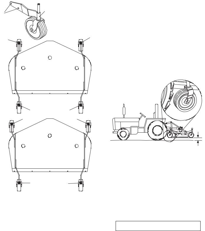
TRACTOR STABILITY
A minimum 25% of tractor and equipment weight must be on the tractor front wheels when attachments are in transport position. Without this weight, tractor could tip over, causing personal injury or death. The weight may be attained with a loader. Weigh the tractor and equipment. Do not estimate.
Figure 1. Tractor Stability
8 Operation |
MAN0180 (Rev. 1/7/2005) |
|
|
ATTACHING MOWER TO TRACTOR

Make sure spring-activated locking pin or collar slides freely and is seated firmly in tractor PTO spline groove.
The standard 1-3/8" 6B-spline driveline with a QD yoke is used to connect the mower to the tractor.
1.Attach the mower hitch pins to the lower tractor lift arms and secure.
2.Attach tractor top link (1), Figure 2, to mower top link bracket attachment point A. Connect the driveline to the tractor PTO shaft.
3.Attach tether chain to tractor drawbar (Figure 3).
4.Adjust the tractor lower 3-point arm anti-sway devices to prevent mower from swinging side to side during transport.
A |
1 |
|
|
B |
|
CD3944 |
|
1. Tractor top link
A.Mower top link attachment point
B.Mower hitch pin
Figure 2. Attachment Points
Tether Chain
CM906
Figure 3. Attach Mower to Tractor
CUTTING HEIGHT ADJUSTMENT

Keep all persons away from operator control area while performing adjustments, service, or maintenance.
IMPORTANT
■ Avoid low cutting heights. Striking the ground with blades produces one of the most damaging shock loads a mower can encounter. Allowing blades to contact ground repeatedly will cause damage to mower and drive.
1.Level mower from side to side. Check by measuring from mower frame to the ground at each deck rail.
2.Verify that the same amount of spacers are under all caster arms.
3.Loosen cap screws that attach caster arm assembly to deck.
4.Set mower on the ground.
5.Retighten cap screws. This equalizes the clearance in the bolt holes.
6.Adjust front of mower level with or slightly lower than the rear to obtain best mowing results.
7.Control cutting height by adjusting front and rear caster wheels.
8.To raise rear of mower, move caster adjustment spacers under rear caster arms, Figure 5.
9.To raise front of mower, move spacers under front caster wheel arms.
 FORWARD
B |
A |
|
CD3551B |
Figure 4. Cutting Height Adjustment
Remember, measurement at location A (Figure 4) should not be less than location B and should not be over 1/2" greater than location B.
MAN0180 (Rev. 1/7/2005) |
Operation 9 |
|
|

|
Table 1: Cutting Height Chart |
|
|
|||
|
|
|
|
|||
|
SPACERS REQUIRED UNDER |
|
|
|||
|
CASTER ARM PIVOT TUBE |
|
|
|||
|
|
|
|
|
|
|
Cut |
|
1/2" |
3/4" |
1" |
1-1/4" |
|
Height |
|
Spacer |
Spacer |
Space |
*Spacer |
|
|
|
|
|
r |
(Spring) |
|
|
|
|
|
|
|
|
1" |
|
|
|
|
|
|
|
|
|
|
|
|
|
1-1/2" |
|
1 |
|
|
|
|
|
|
|
|
|
|
|
2" |
|
|
|
1 |
|
|
|
|
|
|
|
|
|
2-1/2" |
|
1 |
|
1 |
|
Figure 6. Top Link Adjustment |
|
|
|
|
|
|
|
3" |
|
|
|
2 |
|
|
|
|
|
|
|
|
|
3-1/2" |
|
1 |
|
2 |
|
|
|
|
|
|
|
|
|
4" |
* |
|
1 |
1 |
1 |
|
|
|
|
|
|
|
|
4-1/4" |
|
1 |
1 |
2 |
|
|
|
|
|
|
|
|
|
4-1/2" |
* |
1 |
1 |
1 |
1 |
|
|
|
|
|
|
|
|
5" |
* |
|
1 |
2 |
1 |
|
|
|
|
|
|
|
|
5-1/2" |
* |
1 |
1 |
2 |
1 |
|
Figure 7. Gauge Wheel Distance
* RD6000 and RD7200 only
Figure 5. Height Adjustment with Caster Arm Spacers
TRACTOR TOP LINK ADJUSTMENT
When the cutting height is set, adjust tractor top link until mower top link attachment point A is aligned vertically with mower hitch pin B.
Adjust tractor top link so mower is level between caster wheel and ground (dimension C Figure 7). This will allow the mower to follow ground contour.
FRONT CASTER ARM CONFIGURATION
For RD6000-2 & RD7200-2 only
The RD6000-2 and RD7200-2 front casters can be set in two positions using the right and left offset caster arms. Figure 8 shows a right offset assembly.
Check the offset position by looking from mounting hole A to pivot tube B. The pivot tube should be higher than the mounting holes.
Figure 8 shows the two possible configurations for the RD6000-2 and RD7200-2 front caster arms.
●The inner position allows the outside edge of the mower to be used for trimming under shrubs or fences.
●The outer position provides the most clearance for rear tractor tire interference.
To change configurations, remove the cap screws and nuts and move the arms from one side of the machine to the other. Secure with hardware.
The rear caster arms should be mounted as shown.
NOTE: The RD8400-2 front caster arms are fixed and cannot be changed.
10 Operation |
MAN0180 (Rev. 1/7/2005) |
|
|
1B
A |
B |
|
R - Right Offset |
||
RIGHT |
||
L - Left Offset |
||
OFFSET |
||
A - Mounting Holes |
||
|
||
|
B - Pivot Tube |
|
R |
L |
|
|
||
L |
R |
|
L |
R |
|
|
||
CD4990 |
|
|
L |
R |
|
Figure 8. Front Caster Arm Configuration for |
||
RD6000-2 & RD7200-2 Only |
||
FRONT CASTER WHEEL INTERFERENCE CHECK
IMPORTANT
■ Do not operate tractor and mower until this interference check has been performed. If you change tractors, you must perform the check for that mounting.
Perform this check with all of the spacers and springs above the caster wheel arm. This will place the caster
wheels in their highest position and provide the lowest cutting height for the mower.
1.Raise mower with tractor hydraulics to 16" at dimension C or maximum height of tractor lift, whichever is less.
2.Pivot both front caster wheels forward and check that there is clearance between caster wheels and tractor tires.
3.If there is interference on models RD6000-2 and RD7200-2, mount front casters in the outer position.
NOTE: On model RD8400-2, caster wheel width is not adjustable; see tractor operator's manual and adjust tractor wheels to narrower spacing.
C |
CD3528C |
Figure 9. Front Gauge Wheel Interference Check
FRONT ROLLER (OPTIONAL)
The caster wheels and side skids effectively reduce scalping in most cases. However, you may encounter areas where the caster wheels and/or side skids drop into depressions and allow center of the mower to contact ground and scalp. An optional front roller may be installed to minimize scalping.
OPERATING TECHNIQUE
 CAUTION
Stop power unit and implement immediately upon striking an obstruction. Dismount power unit, using proper procedure. Inspect and repair any damage before resuming operation.
Power for operating mower is supplied by tractor PTO. Operate PTO at 540 rpm. Know how to stop tractor and mower quickly in an emergency.
MAN0180 (Rev. 1/7/2005) |
Operation 11 |
|
|
If mower becomes plugged causing belt to slip for over two seconds follow these steps:
1.Maneuver equipment into a previously cut area and allow mower to clear accumulated material.
2.Continue running at least two minutes, allowing pulleys to cool. Stopping the mower in contact with a very hot pulley will bake and ruin belt.
Proper ground speed will depend upon the terrain, the height, and type and density of material to be cut.
12 Operation |
MAN0180 (Rev. 1/7/2005) |
|
|

OWNER PRE-OPERATION CHECK LIST
(OWNER'S RESPONSIBILITY)
___ |
Review and follow all safety rules and safety |
|
decal instructions on pages 3 through 7. |
___ |
Check that all safety decals are installed and in |
|
good condition. Replace if damaged. |
___ |
Check that all shields and guards are properly |
|
installed and in good condition. Replace if dam- |
|
aged. |
___ |
Check that chain shielding is in good condition |
|
and replace any damaged chain links. |
___ |
Check that all hardware and cotter pins are prop- |
|
erly installed and secured. |
___ |
Check to ensure blades are sharp, in good condi- |
|
tion, and installed correctly. Replace if damaged. |
___ |
Check that equipment is properly and securely |
|
attached to tractor. |
___ |
Make sure driveline spring-activated locking pin |
|
or collar slides freely and is seated firmly in trac- |
|
tor PTO spline groove. |
___ Make sure the driveline guards and tether chains are in good condition. Guards must rotate freely on driveline. Fasten tether chains to the tractor and the equipment as instructed.
___ Inspect area and remove stones, branches or other hard objects that might be thrown, causing injury or damage.
___ Do not allow riders.
___ Check all lubrication points and grease as instructed in “Lubrication Information” on page 14. Make sure the PTO slip joint is lubricated and that the gearbox fluid levels are correct.
___ Set tractor PTO at correct rpm for your equipment.
___ Make sure tractor ROPS or ROPS cab and seat belt are in good condition. Keep seat belt securely fastened during operation.
___ Before starting engine, operator must be in tractor seat with seat belt fastened. Place transmission in neutral or park, engage brake, and disengage tractor PTO.
NOTES
MAN0180 (Rev. 1/7/2005) |
Operation 13 |
|
|
 Loading...