


MAN0450 (Rev. 3/9/2010)
BACKHOE
BH70-X, BH80-X
Tested. Proven. Unbeatable.

 OPERATOR'S MANUAL

TO THE DEALER:
Assembly and proper installation of this product is the responsibility of the Woods® dealer. Read manual instructions and safety rules. Make sure all items on the Dealer’s Pre-Delivery and Delivery Check Lists in the Operator’s Manual are completed before releasing equipment to the owner.
The dealer must complete the online Product Registration form at the Woods Dealer Website which certifies that all Dealer Check List items have been completed. Please contact your dealer to complete this form. Dealers can register all Woods product at dealer.WoodsEquipment.com under Product Registration.
Failure to register the product does not diminish customer’s warranty rights.
TO THE OWNER:
Read this manual before operating your Woods equipment. The information presented will prepare you to do a better and safer job. Keep this manual handy for ready reference. Require all operators to read this manual carefully and become acquainted with all adjustment and operating procedures before attempting to operate. Replacement manuals can be obtained from your dealer. To locate your nearest dealer, check the Dealer Locator at www.WoodsEquipment.com, or in the United States and Canada call 1-800-319-6637.
The equipment you have purchased has been carefully engineered and manufactured to provide dependable and satisfactory use. Like all mechanical products, it will require cleaning and upkeep. Lubricate the unit as specified. Observe all safety information in this manual and safety decals on the equipment.
For service, your authorized Woods dealer has trained mechanics, genuine Woods service parts, and the necessary tools and equipment to handle all your needs.
Use only genuine Woods service parts. Substitute parts will void the warranty and may not meet standards required for safe and satisfactory operation. Record the model number and serial number of your equipment in the spaces provided:
Model: _______________________________ |
Date of Purchase: _____________________ |
Serial Number: (see Safety Decal section for location) ____________________________________
Provide this information to your dealer to obtain correct repair parts.
Throughout this manual, the term NOTICE is used to indicate that failure to observe can cause damage to equipment. The terms CAUTION, WARNING, and DANGER are used in conjunction with the Safety-Alert Symbol (a triangle with an exclamation mark) to indicate the degree of hazard for items of personal safety.
|
|
|
|
2 Introduction |
Gen’l (Rev. 3/5/2010) |
||
|
|
|
|

TABLE OF CONTENTS
INTRODUCTION . . . . . . . . . . . . . . . . . . . . . . . . . . . . . . . . . . . . . . . . . . . . . . 2 SPECIFICATIONS . . . . . . . . . . . . . . . . . . . . . . . . . . . . . . . . . . . . . . . . . . . . . 4 GENERAL INFORMATION . . . . . . . . . . . . . . . . . . . . . . . . . . . . . . . . . . . . . . 6 SAFETY RULES . . . . . . . . . . . . . . . . . . . . . . . . . . . . . . . . . . . . . . . . . . . . . . 7 SAFETY DECALS . . . . . . . . . . . . . . . . . . . . . . . . . . . . . . . . . . . . . . . . . . . . 10 OPERATION . . . . . . . . . . . . . . . . . . . . . . . . . . . . . . . . . . . . . . . . . . . . . . . . 12 OWNER SERVICE . . . . . . . . . . . . . . . . . . . . . . . . . . . . . . . . . . . . . . . . . . . 19 TROUBLESHOOTING . . . . . . . . . . . . . . . . . . . . . . . . . . . . . . . . . . . . . . . . 22 DEALER SERVICE . . . . . . . . . . . . . . . . . . . . . . . . . . . . . . . . . . . . . . . . . . . 23 ASSEMBLY . . . . . . . . . . . . . . . . . . . . . . . . . . . . . . . . . . . . . . . . . . . . . . . . . 30 DEALER CHECK LIST . . . . . . . . . . . . . . . . . . . . . . . . . . . . . . . . . . . . . . . . 35 INDEX TO PARTS LISTS . . . . . . . . . . . . . . . . . . . . . . . . . . . . . . . . . . . . . . 37 BOLT TORQUE CHART . . . . . . . . . . . . . . . . . . . . . . . . . . . . . . . . . . . . . . . 50 BOLT SIZE CHART & ABBREVIATIONS . . . . . . . . . . . . . . . . . . . . . . . . . . 51 INDEX . . . . . . . . . . . . . . . . . . . . . . . . . . . . . . . . . . . . . . . . . . . . . . . . . . . . . 52 PRODUCT WARRANTY . . . . . . . . . . . . . . . . . . . . . . . INSIDE BACK COVER REPLACEMENT PARTS WARRANTY . . . . . . . . . . . . . . . . . . .BACK COVER
!LEA EL INSTRUCTIVO!
Si no lee Ingles, pida ayuda a alguien que si lo lea para que le traduzca las medidas de seguridad.
MAN0450 (10/28/2005) |
Introduction 3 |
|
|

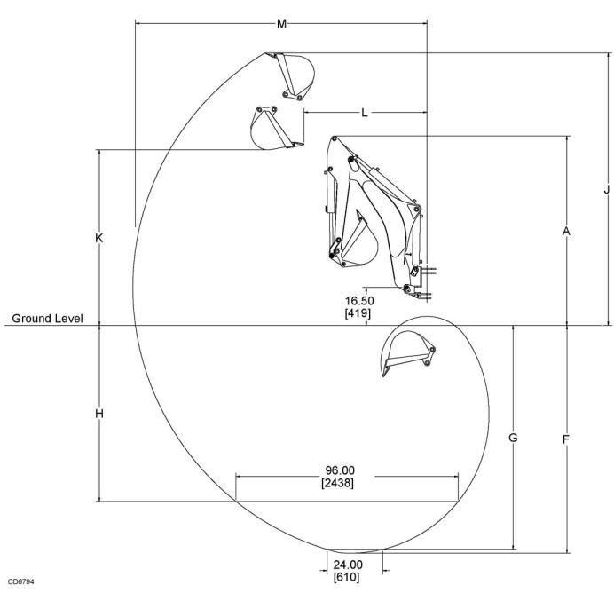
BH70-X & BH80-X SPECIFICATIONS
|
|
English |
Metric |
||
Description |
Illustration |
|
|
|
|
BH70-X |
BH80-X |
BH70-X |
BH80-X |
||
|
|
|
|
|
|
Transport Height* |
A |
74.75" |
82.25" |
1899 mm |
2090 mm |
Stabilizer Spread (Transport)* |
|
58.5" |
58.5" |
1486 mm |
1486 mm |
Angle of Departure** |
|
15° |
15° |
15° |
15° |
Digging Depth, Maximum* |
F |
86.25" |
98." |
2191 mm |
2489 mm |
Digging Depth, 2 ft. Flat Bottom* |
G |
84.5" |
96.5" |
2146 mm |
2451 mm |
Digging Depth, 8 ft. Flat Bottom* |
H |
61.25" |
75.75" |
1556 mm |
1924 mm |
Overall Operating Height* |
J |
108.25" |
117.25" |
2750 mm |
2978 mm |
Loading Height* |
K |
66" |
75.25" |
1676 mm |
1911 mm |
Loading Reach* |
L |
45.25" |
52.5" |
1149 mm |
1334 mm |
Reach from Swing Pivot* |
M |
113.5" |
125.5" |
2883 mm |
3188 mm |
Bucket Rotation* |
|
180° |
180° |
180° |
180° |
Swing Arc* |
|
180° |
180° |
180° |
180° |
Stabilizer Spread (Operating)* |
|
88.5" |
88.5" |
2248 mm |
2248 mm |
Leveling Angle* |
|
10° |
10° |
10° |
10° |
Operating Pressure* |
|
2030 psi |
2470 psi |
14.0 Mpa |
17.0 Mpa |
Operating Flow |
|
4 - 6 gpm |
5 - 7 gpm |
15 - 23 lpm |
19 - 26 lpm |
Bucket Digging Force* |
|
3110 lbs |
3780 lbs |
13834 N |
16814 N |
Dipper Digging Force* |
|
2000 lbs |
2480 lbs |
8896 N |
11032 N |
|
|
|
|
|
|
Bucket Capacity (Heaped) |
|
cu.-ft. |
cu.-meter |
|
|
|
|
9" (203 mm) |
|
0.77 |
0.022 |
12" (305 mm) |
|
1.13 |
0.032 |
16" (406 mm) |
|
1.64 |
0.046 |
18" (457 mm) |
|
1.90 |
0.054 |
24" (610 mm) |
|
2.67 |
0.075 |
|
|
|
|
*Per Definitions in SAE J49 Standard
**Per Definitions in SAE J1234 Standard
4 Introduction |
MAN0450 (10/28/2005) |
|
BH70-X & BH80-X SPECIFICATIONS
MAN0450 (10/28/2005) |
Introduction 5 |
|
|
GENERAL INFORMATION
The purpose of this manual is to assist in setting up, operating and maintaining your backhoe. Read it carefully. It furnishes information and instructions that will help you achieve years of dependable performance.
These instructions have been compiled from extensive field experience and engineering data. Some information may be general in nature due to unknown and varying conditions. However, through experience and these instructions, you should be able to develop procedures suitable to your particular situation.
The illustrations and data used in this manual were current at the time of printing, but due to possible in-line production changes, your machine may vary slightly in detail. We reserve the right to redesign and change the machines as may be necessary without notification.

■ Some illustrations in this manual show the backhoe with safety shields removed to provide a better view. The backhoe should never be operated with any safety shielding removed.
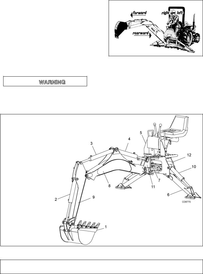
Figure 1. Backhoe Directions
Throughout this manual, references are made to right, left, forward and rearward directions. These are determined from the backhoe operator seat position facing rearward as shown in Figure 1.
Terms for backhoe components have some variations throughout the industry. We use SAE designations as shown in Figure 2.
1.Bucket
2.Bucket cylinder
3.Dipper cylinder
4.Boom cylinder
5.Console
6.Stabilizer
7.Swing cylinder
8.Boom
9.Dipper
10.Stabilizer cylinder
11.Swing frame
12.Main frame
Figure 2. Backhoe Components
6 Introduction |
MAN0450 (10/28/2005) |
|

SAFETY RULES
ATTENTION! BECOME ALERT! YOUR SAFETY IS INVOLVED!
Safety is a primary concern in the design and manufacture of our products. Unfortunately, our efforts to provide safe equipment can be wiped out by an operator’s single careless act.
In addition to the design and configuration of equipment, hazard control and accident prevention are dependent upon the awareness, concern, judgement, and proper training of personnel involved in the operation, transport, maintenance, and storage of equipment.
It has been said, “The best safety device is an informed, careful operator.” We ask you to be that kind of operator.
INSTALLATION
Hydraulics must be connected as instructed in this manual. Do not substitute parts, modify, or connect in any other way.
After connecting hoses, check that all control lever positions function as instructed in the Operator's Manual. Do not put into service until control lever and equipment movements are correct.
TRAINING
Safety instructions are important! Read all attachment and power unit manuals; follow all safety rules and safety decal information. (Replacement manuals and safety decals are available from your dealer. To locate your nearest dealer, check the Dealer Locator at www.WoodsEquipment.com, or in the United States and Canada call 1-800-319- 6637.) Failure to follow instructions or safety rules can result in serious injury or death.
If you do not understand any part of this manual and need assistance, see your dealer.
Know your controls and how to stop engine and attachment quickly in an emergency.
Operators must be instructed in and be capable of the safe operation of the equipment, its attachments, and all controls. Do not allow anyone to operate this equipment without proper instructions.
Keep hands and body away from pressurized lines. Use paper or cardboard, not hands or other body parts to check for leaks. Wear safety goggles. Hydraulic fluid under pressure can easily penetrate skin and will cause serious injury or death.
Make sure that all operating and service personnel know that if hydraulic fluid penetrates skin, it
must be surgically removed as soon as possible by a doctor familiar with this form of injury or gangrene, serious injury, or death will result. CONTACT A PHYSICIAN IMMEDIATELY IF FLUID ENTERS SKIN OR EYES. DO NOT DELAY.
Never allow children or untrained persons to operate equipment.
PREPARATION
Check that all hardware is properly installed. Always tighten to torque chart specifications unless instructed otherwise in this manual.
Air in hydraulic systems can cause erratic operation and allows loads or equipment components to drop unexpectedly. When connecting equipment or hoses or performing any hydraulic maintenance, purge any air in hydraulic system by operating all hydraulic functions several times. Do this before putting into se rvice or allowing any one to approach the equipment.
After connecting hoses, check that all control lever positions function as instructed in the Operator's Manual. Do not put into service until control lever and equipment movements are correct.
Protective hose sleeves must cover all hydraulic hoses within 20 inches of the operator and be secured onto metal hose fittings. Replace hoses or sleeves if damaged or if protective sleeve cannot be properly positioned or secured.
Make sure all hydraulic hoses, fittings, and valves are in good condition and not leaking before starting power unit or using equipment. Check and route hoses carefully to prevent damage. Hoses must not be twisted, bent sharply, kinked, frayed, pinched, or come into contact with any moving parts. Operate moveable components through full operational range to check clearances. Replace any damaged hoses immediately.
Always wear relatively tight and belted clothing to avoid getting caught in moving parts. Wear sturdy, rough-soled work shoes and protective equipment for eyes, hair, hands, hearing, and head; and respirator or filter mask where appropriate.
Make sure spring-activated locking pin or collar slides freely and is seated firmly in tractor PTO spline groove.
Make sure attachment is properly secured, adjusted, and in good operating condition.
(Safety Rules continued on next page)
BH6500/7500/9000_SR (Rev. 6/23/2006)
Safety 7

SAFETY RULES
ATTENTION! BECOME ALERT! YOUR SAFETY IS INVOLVED!
(Safety Rules continued from previous page)
Power unit must be equipped with ROPS or ROPS cab and seat belt. Keep seat belt securely fastened. Falling off power unit can result in death from being run over or crushed. Keep foldable ROPS system in “locked up” position at all times.
Only mount this backhoe on Category 1 tractors with 800 lb. lift capacity at 24" behind 3-point lift arm hitch balls.
Never put backhoe into service unless backhoe manufacturer's 3-point hitch Saf-T-Lok® limiter or sub-frame has been installed and adjusted.
To avoid possible hitch failure, read and follow the Saf-T-Lok Limiter Installation Instructions in the Assembly section before mounting backhoe to tractor 3-point hitch.
Remove seat and upper support assembly before installing or removing backhoe from tractor. Failure to comply may result in equipment failure and/or personal injury.
Do not operate backhoe unless there is adequate operator clearance as shown on safety decal. (Refer to Danger decal in Safety Decal section.)
Always use the special heavy-duty top link (provided with backhoe) and the OEM high-strength top link pin (provided with tractor) to mount the top link to tractor. Use 3/4" x 3-1/2" grade 5 bolt(s) to mount top link to backhoe.
Be sure that backhoe is properly mounted, adjusted, and in good operating condition.
Place and keep 3-point lift quadrant lever in lowered position at all times.
If tractor is equipped with draft sensing control, set control to “HEAVY” (minimum sensitivity) position.
Make sure all safety decals are installed. Replace if damaged. (See Safety Decals section for location.)
Make sure shields and guards are properly installed and in good condition. Replace if damaged.
A minimum 20% of tractor and equipment weight must be on tractor front wheels with backhoe in transport position. Without this weight, tractor could tip over, causing personal injury or death. The weight may be attained with a loader, front wheel weights, ballast in tires, or front tractor weights. When attaining the minimum 20% weight on the front wheels, you must not exceed the Roll
Over Protection Structure (ROPS) weight certification. Weigh the tractor and equipment. Do not estimate.
Do not install backhoe and required counterweights on tractor if the total tractor and equipment weight then exceeds the ROPS weight certification of the tractor. To reduce overall weight of unit, remove liquid from rear tires and remove midmount mower, if equipped.
Clean all dirt, trash, and grease from operator's platform and steps.
OPERATION
Do not allow bystanders in the area when operating, attaching, removing, assembling, or servicing equipment.
Before operating, make sure stabilizer pads are lowered firmly to the ground. Stabilizer arms provide support for the backhoe and support for the backhoe mounting brackets.
Consult local utilities before working. Know location of all underground cables, pipelines, overhead wires, and other hazards in working area and avoid contact.
Keep bystanders away from operator, stabilizer, and maximum bucket swing areas.
Do not operate or transport equipment while under the influence of alcohol or drugs.
Operate only in daylight or good artificial light.
Always comply with all state and local lighting and marking requirements.
Do not allow riders. Do not lift or carry anybody on the power unit or attachments.
Power unit must be equipped with ROPS or ROPS cab and seat belt. Keep seat belt securely fastened. Falling off power unit can result in death from being run over or crushed. Keep foldable ROPS system in “locked up” position at all times.
The only time the backhoe may be operated from a position other than the operator seat is during backhoe attachment and removal. Operator must:
•Read Mounting Kit Manual instructions on attaching and removing backhoe and use extreme care.
•Always stand between rear tire and backhoe stabilizer arms or along side of tractor to avoid being trapped should the boom swing control be accidentally activated.
8 Safety
BH6500/7500/9000_SR (Rev. 6/23/2006)

SAFETY RULES
ATTENTION! BECOME ALERT! YOUR SAFETY IS INVOLVED!
When operating controls, always sit in backhoe seat.
Operate tractor PTO at 540 RPM. Do not exceed.
Always dump spoil at least two feet away from opening.
Use extreme care when working close to fences, ditches, other obstructions, or on hillsides.
Be careful when swinging loaded bucket on a hillside. Always dump spoil on uphill side of backhoe to minimize the possibility of upset.
Never leave equipment unattended with engine running or with bucket in raised position. Always engage swing and boom transport locks, relieve system pressure by operating controls, and remove ignition key before leaving equipment.
Do not use backhoe for craning; it is primarily designed for digging. Mechanical failures such as hose rupture will cause a load to drop suddenly.
TRANSPORTATION
Always engage swing and boom transport locks and attach Slow Moving Vehicle (SMV) sign before transporting backhoe.
Power unit must be equipped with ROPS or ROPS cab and seat belt. Keep seat belt securely fastened. Falling off power unit can result in death from being run over or crushed. Keep foldable ROPS system in “locked up” position at all times.
Never exceed 20 mph (32.2 km/h) during transport.
Always comply with all state and local lighting and marking requirements.
Never allow riders on power unit or attachment.
Do not operate PTO during transport.
Do not operate or transport on steep slopes.
A minimum 20% of tractor and equipment weight must be on tractor front wheels with backhoe in transport position. Without this weight, tractor could tip over, causing personal injury or death. The weight may be attained with a loader, front wheel weights, ballast in tires, or front tractor weights. When attaining the minimum 20% weight on the front wheels, you must not exceed the Roll Over Protection Structure (ROPS) weight certification. Weigh the tractor and equipment. Do not estimate.
Do not operate or transport equipment while under the influence of alcohol or drugs.
MAINTENANCE
Do not modify or alter or permit anyone else to modify or alter the equipment or any of its components in any way.
Do not allow bystanders in the area when operating, attaching, removing, assembling, or servicing equipment.
Your dealer can supply original equipment hydraulic accessories and repair parts. Substitute parts may not meet original equipment specifications and may be dangerous.
Adjustment of system relief pressure must be done by a qualified, experienced dealership. Incorrect adjustment can result in system failures and serious personal injury.
Always wear relatively tight and belted clothing to avoid getting caught in moving parts. Wear sturdy, rough-soled work shoes and protective equipment for eyes, hair, hands, hearing, and head; and respirator or filter mask where appropriate.
Dealer service personnel must perform work that requires engine operation during service.
Before working on backhoe, extend boom and dipperstick and place bucket on ground. Make sure that all system pressure has been relieved by operating controls before performing maintenance or service or before disconnecting any hydraulic lines.
Keep all persons away from operator control area while performing adjustments, service, or maintenance.
Tighten all bolts, nuts, and screws to torque chart specifications. Check that all cotter pins are installed securely to ensure equipment is in a safe condition before putting unit into service.
Make sure all safety decals are installed. Replace if damaged. (See Safety Decals section for location.)
Make sure shields and guards are properly installed and in good condition. Replace if damaged.
STORAGE
Block equipment securely for storage.
Keep children and bystanders away from storage area.
Refer to Removing and Storing Backhoe in Operation section of backhoe manual.
(Rev. 7/7/2006)
BH6500/7500/9000_SR (Rev. 6/23/2006)
Safety 9
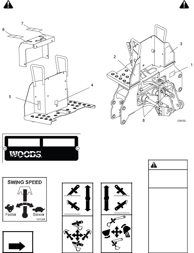
SAFETY & INSTRUCTIONAL DECALS
ATTENTION! BECOME ALERT! YOUR SAFETY IS INVOLVED!
Replace Immediately If Damaged!
1 - SERIAL NUMBER PLATE
MODEL NO. |
SERIAL NO. |
|
Woods Equipment Company |
|
Oregon, Illinois, U.S.A. |
4 - PN 1011994
BH80-X Only
8 - PN 33437
LOCK
33437-E
6 - PN 37885 |
FLOAT |
37885-A |
7 - PN 37884 |
37884-A |
5 - PN 1008365
HIGHHYDRAULIC
CAN PENETRATE SKIN AND RESULT IN SEVERE INJURY, GANGRENE OR DEATH.
Check for leaks with cardboard; never use hand.
Before you loosen fittings: lower load, release pressure, and be sure oil is cool.
See a doctor at once if oil enters skin.
1008365
10 Safety |
MAN0450 (10/28/2005) |
|
|

SAFETY & INSTRUCTIONAL DECALS
ATTENTION! BECOME ALERT! YOUR SAFETY IS INVOLVED!
Replace Immediately If Damaged!
|
|
|
|
2 - PN 1011992 |
|
|
|
|
|
|
|
|
|
|
|
|
3 - PN 1011993 |
||||||||||||
|
|
|
|
|
|
|
|
|
|
|
|
|
|
|
|
|
|
|
|
|
|
|
|
|
|
|
|
|
|
|
|
|
|
|
|
|
|
|
|
|
|
|
|
|
|
|
|
|
|
|
|
|
|
|
|
|
|
|
|
|
|
|
|
|
|
|
|
|
|
|
|
|
|
|
|
|
|
|
|
|
|
|
|
|
|
|
|
|
|
|
|
|
|
|
|
|
|
|
|
|
|
|
|
|
|
|
|
|
|
|
|
|
|
|
|
|
|
|
|
|
|
|
|
|
|
|
|
|
|
|
|
|
|
|
|
|
|
|
|
|
|
|
|
|
|
|
|
|
|
|
|
|
|
|
|
|
|
|
|
|
|
|
|
|
|
|
|
|
|
|
|
|
|
|
|
|
|
|
|
|
|
|
|
|
|
|
|
|
|
|
|
|
|
|
|
|
|
|
|
|
|
|
|
|
|
|
|
|
|
|
|
|
|
|
|
|
|
|
|
|
|
|
|
|
|
|
|
|
|
|
|
|
|
|
|
|
|
|
|
|
|
|
|
|
|
|
|
|
|
|
|
|
|
|
|
|
|
|
|
|
|
|
|
|
|
|
|
|
|
|
|
|
|
|
|
|
|
|
|
|
|
|
|
|
|
|
|
|
|
|
|
|
|
|
|
|
|
|
|
|
|
|
|
|
|
|
|
|
|
|
|
|
|
|
|
|
|
|
|
|
|
|
|
|
|
|
|
|
|
|
|
|
|
|
|
|
|
|
|
|
|
|
|
|
|
|
|
|
|
|
|
|
|
|
|
|
|
|
|
|
|
|
|
|
|
|
|
|
|
|
|
|
|
|
|
|
|
|
|
|
|
|
|
|
|
|
|
|
|
|
|
|
|
|
|
|
|
|
|
|
|
|
|
|
|
|
|
|
|
|
|
|
|
|
|
|
|
|
|
|
|
|
|
|
|
|
|
|
|
|
|
|
|
|
|
|
|
|
|
|
|
|
|
|
|
|
|
|
|
|
|
|
|
|
|
|
|
|
|
|
|
|
|
|
|
|
|
|
|
|
|
|
|
|
|
|
|
|
|
|
|
|
|
|
|
|
|
|
|
|
|
|
|
|
|
|
|
|
|
|
|
|
|
|
|
|
|
|
|
|
|
|
|
|
|
|
|
|
|
|
|
|
|
|
|
|
|
|
|
|
|
|
|
|
|
|
|
|
|
 "
" 


BE CAREFUL!
Use a clean, damp cloth to clean safety decals.
Avoid spraying too close to decals when using a pressure washer; high-pressure water can enter through very small scratches or under edges of decals causing them to peel or come off.
Replacement safety decals can be ordered free from your Woods dealer. To locate your nearest dealer, check the Dealer Locator at www.WoodsEquipment.com, or in the
United States and Canada call 1-800-319-6637.
MAN0450 (10/28/2005) |
Safety 11 |
|
|
OPERATION
The operator is responsible for the safe operation of the backhoe. The operator must be properly trained. Operators should be familiar with the backhoe, the tractor, and all safety practices before starting operation. Read the safety rules and safety decals on pages 7 to 11.

Never put backhoe into service unless backhoe manufacturer's 3-point hitch Saf-T-Lok® limiter or sub-frame has been installed and adjusted.
Do not operate backhoe unless there is adequate operator clearance as shown on safety decal. (Refer to Danger decal in Safety Decal section.)

Make sure all hydraulic hoses, fittings, and valves are in good condition and not leaking before starting power unit or using equipment. Check and route hoses carefully to prevent damage. Hoses must not be twisted, bent sharply, kinked, frayed, pinched, or come into contact with any moving parts. Operate moveable components through full operational range to check clearances. Replace any damaged hoses immediately.
Make sure that all operating and service personnel know that if hydraulic fluid penetrates skin, it must be surgically removed as soon as possible by a doctor familiar with this form of injury or gangrene, serious injury, or death will result. CONTACT A PHYSICIAN IMMEDIATELY IF FLUID ENTERS SKIN OR EYES. DO NOT DELAY.
Keep hands and body away from pressurized lines. Use paper or cardboard, not hands or other body parts to check for leaks. Wear safety goggles. Hydraulic fluid under pressure can easily penetrate skin and will cause serious injury or death.
Consult local utilities before working. Know location of all underground cables, pipelines, overhead wires, and other hazards in working area and avoid contact.
A minimum 25% of tractor and equipment weight must be on the tractor front wheels when attachments are in transport position. Without this weight, tractor could tip over, causing personal injury or death. The weight may be attained with a loader, front wheel weights, ballast in tires, or front tractor weights. Weigh the tractor and equipment. Do not estimate.
START AND STOP OPERATION

Operate tractor PTO at 540 RPM. Do not exceed.
An optional tractor-driven PTO pump supplies hydraulic pressure for backhoe operation. Instructions for engaging and disengaging the PTO are in your tractor manual. Learn how to disengage PTO quickly should an emergency occur.
Never exceed 540 rpm. Operating the pump in excess of 540 rpm will cause overheating and equipment damage.
GENERAL OPERATION

Place and keep 3-point lift quadrant lever in lowered position at all times.
If tractor is equipped with draft sensing control, set control to “HEAVY” (minimum sensitivity) position.
Do not use backhoe for craning; it is primarily designed for digging. Mechanical failures such as hose rupture will cause a load to drop suddenly.
Never allow children or untrained persons to operate equipment.
 CAUTION
When operating controls, always sit in backhoe seat.
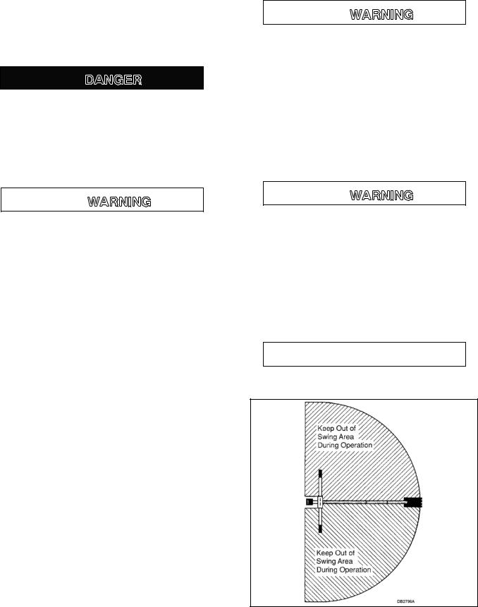
Figure 1. Backhoe Swing Area.
12 Operation |
MAN0450 (10/28/2005) |
|
|
Mechanical failures such as a hose rupture will cause a load to drop. Lifting a heavy load with the dipper, then operating the boom, could cause boom to drop. In either case, if anyone is in the operating area (maximum reach of bucket) as shown in Figure 1, serious injury or death could occur.
Do not dig with backhoe unless stabilizers are down and on a firm surface. Stay clear of steep areas or excavation banks that are soft or could give way
POSITION THE MACHINE
Before operating in an unfamiliar area, walk around the full length of the proposed site and check for hidden holes, drop-off or obstacles that could cause an accident.
Lower stabilizers until they carry the weight of the backhoe. If tractor is equipped with a front loader, place the bucket flat on the ground. Lower loader lift arms until weight is removed from front tractor tires.
Level the machine using stabilizers and front loader before starting to dig.
Stability is very important when operating backhoe in the extreme swing positions as this causes weight transfer.
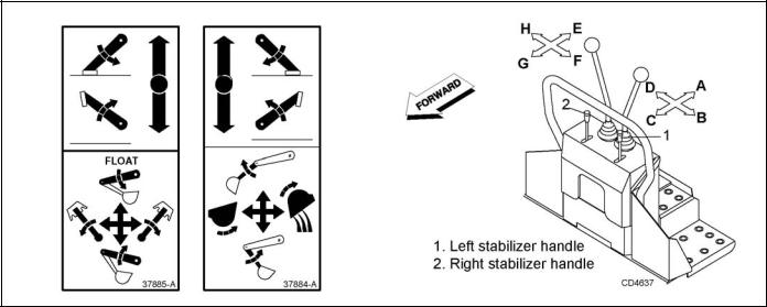
CONTROL HANDLE OPERATION
Refer to Figure 2.
Assume your position in the operator's seat.
When engaging optional PTO-mounted pump, engine rpm should always be low. Once engaged, engine rpm may be increased to desirable operation speed (not to exceed 540 rpm).
When becoming familiar with backhoe controls, start with a lower rpm.
Before operating, perform a functional test by placing control handles in their various positions and making certain correct operation occurs, matching decals on operator's console. Pay specific attention to float position of boom. Do not operate backhoe if functions differ from decal; serious injury or death could occur.
It is not difficult to become a successful operator. Control lever operating decals (shown in Figure 4) are next to the operating control levers. Study these decals; they will assist you in becoming familiar with the controls.
Pushing handle 1 forward will lower left stabilizer; pulling back raises it.
Pushing handle 2 forward will lower right stabilizer; pulling back raises it.
Pulling left control back (toward A) raises boom; pushing it forward (toward C) lowers it. Full forward (toward C) is the float position.
Moving left handle left (toward B) swings boom left; moving it right (toward D) swings boom right.
Pulling right control back (toward E) moves dipper down and toward operator; pushing it forward (toward G) moves it up and away from operator.
Moving right handle left (toward F) curls bucket toward operator; moving it right (toward H) extends bucket out away from operator.
Operate the control levers, swinging the boom several times to practice control. Do not operate the swing more than 45 degrees each way the first few times. Gradually increase arc.
Figure 2. Operator’s Controls (Typical View)
MAN0450 (10/28/2005) |
Operation 13 |
|
|
After becoming familiar with the backhoe operation, practice coordinated use of the controls in a safe open area at reduced engine speed. Gradually increase engine speed as the technique is mastered.
Operate backhoe gently and smoothly. Avoid swinging boom into mainframe. Sudden stopping or jerking could result in serious damage to tractor and backhoe.
Strive to develop a smooth digging cycle. Avoid abrupt or jerky movements. This is accomplished by operating two or more controls at the same time and not allowing the cylinders to reach the limit of travel.
Should you become confused during operation, simply let go of the controls. The valve control handles will automatically return to neutral.
BH80-X SWING SPEED CONTROL
The swing speed control valve is located on the back side of the console on BH80-X backhoes only. This controls the speed of the swing cylinders and allows for easier operation in tight areas. Turn knob to the right to Decrease swing speed and to the left to increase swing speed.
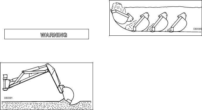
START EXCAVATION

Consult local utilities before working. Know location of all underground cables, pipelines, overhead wires, and other hazards in working area and avoid contact.
Figure 3. Starting Position
To start the excavation, position backhoe as shown in Figure 3 for maximum breakout force.
Actuate the dipper cylinder to start digging. Approximately halfway through digging cycle, start bucket curl while continuing crowding dipper in. Should bucket stall, raise boom slightly.
Do not use down pressure on the boom when starting to dig, as this will lift the machine and move it out of alignment with the work.
FILL BUCKET
Control bucket attitude throughout digging cycle to keep teeth parallel to bottom of excavation. This will provide best penetration angle and minimize dragging and scraping bucket through the ground.
Penetration depth is determined by soil condition and type.
Only use dipper and bucket during the digging cycle. As the dipper moves the bucket through the soil, curl bucket to maintain proper bucket position.
At the end of the pass, or when bucket is full, curl bucket completely, lift bucket from excavation and swing boom to dump site.
To obtain a cleaner trench and avoid material buildup directly in front of backhoe, extend dipper and curl bucket completely while starting to lift it out of the excavation. This will allow excess material to fall back into the excavation.
Figure 4. Fill Bucket
DUMP AND RETURN CYCLE
Keep the swing-dump-return cycle as brief as possible. Keep dipper moving outward and start boom swing as soon as the bucket clears the excavation. Continue extending dipper and, as you approach the spoil pile, start to dump bucket.
When bucket is empty, dipper and bucket are in position to resume digging upon return to the excavation.
TRENCHING AND EXCAVATING
Refer to Figure 5.
Trenching is the most basic backhoe digging operation. Other operations are variations of this basic function.
To maintain a level trench bottom, set bucket at proper approach angle and while crowding dipper-stick in, continually move bucket curl lever to maintain correct cutting angle. At the same time, place boom control in the full forward (float) position and keep the bucket in the same plane.
When handle is placed in the float position, pressure on both sides of boom cylinder is released.
14 Operation |
MAN0450 (10/28/2005) |
|
|
Digging near center of swing so material may be dumped on either side will produce good results. Never dig near stabilizers.
Continue the trench by moving machine along trench centerline away from existing excavation. Move machine approximately one-half the effective backhoe reach. Moving too far will require excessive down pressure for digging and hand clean-up of trench bottom.
Figure 5. Trenching
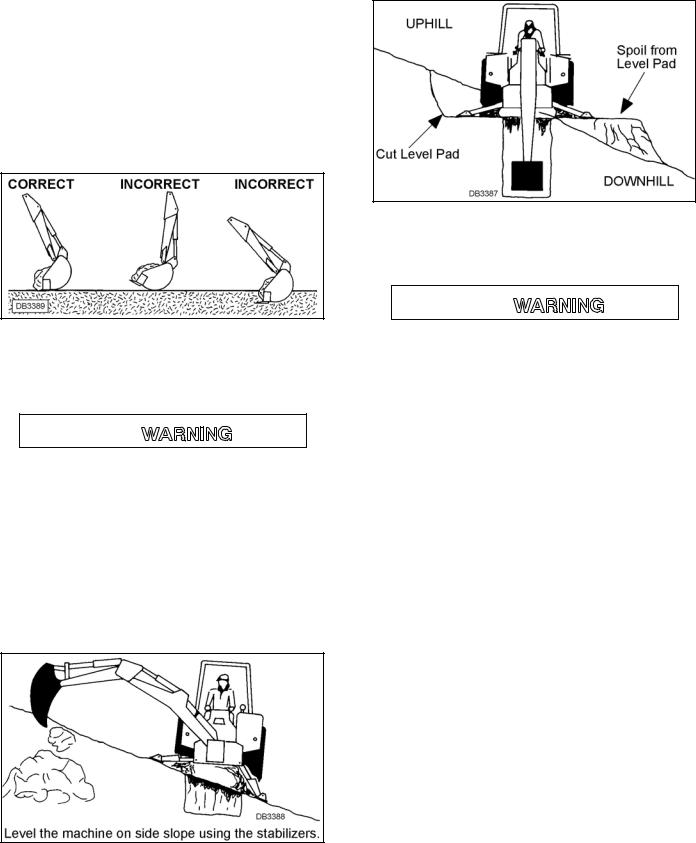
SIDE SLOPE TRENCHING / EXCAVATING

Be careful when swinging loaded bucket on hillside. Always dump spoil on uphill side of backhoe to minimize rollover possibility.
When operating on a side slope, the backhoe must be positioned using one of these two methods as shown in Figure 6 or Figure 7.
When operating on a side slope, always place the trench spoil on the uphill side.
Figure 6. Level with Stabilizers
Cut a level pad for the uphill side of the machine and place spoil on the downhill side as shown in Figure 7.
Figure 7. Level with Cut Out
TRANSPORTING

Always engage swing and boom transport locks and attach Slow Moving Vehicle (SMV) sign before transporting backhoe.
Power unit must be equipped with ROPS or ROPS cab and seat belt. Keep seat belt securely fastened. Falling off power unit can result in death from being run over or crushed. Keep foldable ROPS system in “locked up” position at all times.
Never leave equipment unattended with engine running or with bucket in raised position. Always engage swing and boom transport locks, relieve system pressure by operating controls, and remove ignition key before leaving equipment.
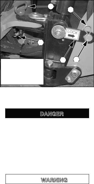
Transport and Swing Lock Installation
IMPORTANT
■ Before operating backhoe, disengage transport lock bar and store swing lock pin. Push transport lock bar down fully to prevent damage.
Engage transport lock by fully retracting boom and dipper. Position transport lock bar (1), located on right side of swing frame, over transport lock pin (2). Secure with safety pin (4). See Figure 8.
Center boom from side to side and install swing lock pin (3) through swing frame and main frame. Secure swing lock pin (3) with a safety pin (4) as shown.
During backhoe operation, store swing lock pin (3) in the hole provided on the back side of the seat post. Secure into position with safety pin (4).
Always raise stabilizers before transporting backhoe.
MAN0450 (10/28/2005) |
Operation 15 |
|
|
|
3 |
4 |
|
|
|
|
4 |
|
|
1 |
2 |
1. |
Transport lock bar |
|
2. |
Transport lock pin |
|
3. |
Swing lock pin |
|
4. |
Safety pin |
DP1 |
Figure 8. Transport and Swing Lock Installed
REMOVING AND STORING BACKHOE

The only time the backhoe may be operated from a position other than the operator seat is during backhoe attachment and removal. Operator must:
•Read Mounting Kit Manual instructions on attaching and removing backhoe and use extreme care.
•Always stand between rear tire and backhoe stabilizer arms or along side of tractor to avoid being trapped should the boom swing control be accidentally activated.

Keep all persons away from operator control area while performing adjustments, service, or maintenance.
Remove seat and upper support assembly before installing or removing backhoe from power unit. Failure to comply may result in equipment failure and/or personal injury.
3-Point Mount Removal
Position tractor on a hard level surface, remove swing lock pin and transport bar, and center the backhoe boom.
Lower stabilizers and take weight of backhoe off of rear tractor tires.
Lower boom and dipper to form 90-degree angle and rest bucket on the ground.
Remove pin that attaches top link to tractor. Remove lower 3-point arms from backhoe. Place blocks under mainframe and raise stabilizers to lower backhoe mainframe onto blocks. Block backhoe as necessary to make it stable.
Disconnect hydraulic system.
4-Point Sub-Frame Mount Removal
NOTE: See the sub-frame mounting kit manual that fits your tractor for specific instructions.
Position tractor on a hard level surface, remove swing lock pin and transport bar, and center the backhoe boom.
Lower stabilizers and take weight of backhoe off of rear tractor tires.
Lower boom and dipper to form 90-degree angle and rest bucket on the ground.
Remove the seat assembly.
Remove klik pins from bolt and nut assemblies.
Use 1-1/2 inch open end wrench supplied with the mounting kit to remove hex nuts. Return wrench to storage position.
Use the boom to relieve excess pressure on 1-inch bolts and remove bolts.
Tilt backhoe mainframe forward and away from subframe.
Raise stabilizers (to lower backhoe) until backhoe brackets slide out of hooks on the sub-frame. Lower backhoe approximately 1-1/2 inch.
Move tractor forward to clear backhoe brackets.
Place 6 inch blocks under backhoe mainframe and raise stabilizers to lower backhoe to the storage position on blocks. Boom and dipper should be at 90degree angle.
Disconnect hydraulic system.
Disconnect Tractor Hydraulics
For Backhoe Powered with Auxiliary Pump
Disengage the PTO, stop tractor engine and remove key. Remove pump from PTO and secure it on backhoe. Move tractor carefully away from backhoe.
For Tractors with Open-Center Valves (Figure 9)
Stop tractor and remove key.
Disconnect pressure and return hoses. Connect tractor pressure and return hoses together to complete opencenter circuit. Connect backhoe pressure and return hoses together for storage.
16 Operation |
MAN0450 (10/28/2005) |
|
|
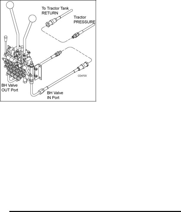
NOTE: Circuit must be complete to prevent damage to tractor hydraulic system.
Figure 9. Tractors with Open-Center Valves
MECHANICAL THUMB (OPTIONAL)
The mechanical thumb is used for grabbing objects and securing them between the thumb and the bucket.
Become familiar with the geometry and extra weight the thumb adds to the backhoe before operating. Large heavy objects such as rocks and logs can increase momentum when pivoting backhoe to the side. DO NOT make sudden stops and starts. Be extremely careful lifting and moving long items such as poles or tree limbs which may extend beyond the normal backhoe operating area.
Improper usage can also damage the thumb or backhoe. DO NOT use the thumb to rake material, push or pull material, use the side of the thumb to move material, use as a lifting devise with chain or rope, or as a pry bar to dislodge objects.
Place thumb in operating position by selecting an appropriate pin location on the telescoping tube. Rotate the bucket to hold material against the thumb.
When normal backhoe operation is required, place thumb in storage position. Remove pin, rotate thumb up against dipper, and insert pin to lock thumb into position.
PRE-OPERATION CHECK LIST
(OWNER'S RESPONSIBILITY)
The operator should perform the following check list before operating backhoe.
___ Check that backhoe is properly and securely attached to tractor.
___ Make sure all hydraulic connections are tight and all hydraulic lines and hoses are in good condition before engaging tractor PTO.
___ Check that there are no leaks in the hydraulic system. Before operating, all hydraulic hoses must be routed properly and not be twisted, bent sharply, kinked, pulled tight or frayed.
___ During inspection, check that all nuts and bolts are secure and clevis pins are properly cotter pinned.
___ Be sure special heavy-duty top link, provided with backhoe, is installed.
___ Make sure only original equipment highstrength top link pin, provided with tractor, is used to attach top link to tractor.
___ Use a 3/4" x 3-1/2" grade 5 bolt to mount top link to backhoe.
___ Make sure tractor lower lift arm stabilizers (blocks or chains) are positioned to prevent lift arms and backhoe from swaying.
___ Place all backhoe controls in neutral position before starting tractor engine.
___ Check hydraulic reservoir level.
MAN0450 (10/28/2005) |
Operation 17 |
|
|
 Loading...