


2300012 LOADER MOUNTING KIT
for LUP126-2, LUP132-2 Loaders
on New Holland® Tractors T5040, T5050, T5060, T5070 2WD & FWA
or Case IH® Tractors Farmall® 85U, Farmall 95U, Farmall 105U 2WD & FWA
includes Hose Kits 58025, 1028835
MAN0788 |
|
SAVE |
THIS |
|
|||
|
|
|
|
|
|||
(1/16/2009) |
MANUAL! . |
||||||
|
|
|
it |
with |
|||
|
|
|
|
|
|||
|
|
|
|
|
Manual |
||
|
|
Include |
|||||
|
|
|
Loader safety, |
||||
|
|
your |
|
|
|
repair |
|
|
|
It |
containsand |
|
|||
|
|
|
|
informationother |
|||
|
|
|
|
|
|||
|
|
operation, |
in |
||||
|
|
|
part |
|
|||
|
|
|
not |
found . |
|||
|
|
|
|
manuals |
|||
|
|
|
|
|
|
|
|

 INSTALLATION MANUAL

TO THE DEALER:
Assembly and proper installation of this product is the responsibility of the Woods® dealer. Read manual instructions and safety rules. Make sure all items on the Dealer’s Pre-Delivery and Delivery Check Lists in the Loader Operator’s Manual are completed before releasing equipment to the owner.
TO THE OWNER:
Read this manual and Loader Operator’s Manual before operating your Woods equipment. The information presented will prepare you to do a better and safer job. Keep this manual handy for ready reference. Require all operators to read this manual carefully and become acquainted with all adjustment and operating procedures before attempting to operate. Replacement manuals can be obtained from your dealer. To locate your nearest dealer, check the Dealer Locator at www.WoodsEquipment.com, or in the United States and Canada call 1-800-319-6637.
The equipment you have purchased has been carefully engineered and manufactured to provide dependable and satisfactory use. Like all mechanical products, it will require cleaning and upkeep. Lubricate the unit as specified. Observe all safety information in this manual and safety decals on the equipment.
For service, your authorized Woods dealer has trained mechanics, genuine Woods service parts, and the necessary tools and equipment to handle all your needs.
Use only genuine Woods service parts. Substitute parts will void the warranty and may not meet standards required for safe and satisfactory operation. Record the model number of your equipment in the space provided.
Model: _______________________________ |
Date of Purchase: _____________________ |
Provide this information to your dealer to obtain correct repair parts.
Throughout this manual, the term NOTICE is used to indicate that failure to observe can cause damage to equipment. The terms CAUTION, WARNING, and DANGER are used in conjunction with the Safety-Alert Symbol (a triangle with an exclamation mark) to indicate the degree of hazard for items of personal safety.
2 Introduction
LMK (Rev. 7/20/2007)

SAFETY RULES
ATTENTION! BECOME ALERT! YOUR SAFETY IS INVOLVED!
!LEA EL INSTRUCTIVO!
Si no lee Ingles, pida ayuda a alguien que si lo lea para que le traduzca las medidas de seguridad.
Safety is a primary concern in the design and manufacture of our products. Unfortunately, our efforts to provide safe equipment can be wiped out by an operator’s single careless act.
In addition to the design and configuration of equipment, hazard control and accident prevention are dependent upon the awareness, concern, judgement, and proper training of personnel involved in the operation, transport, maintenance, and storage of equipment.
It has been said, “The best safety device is an informed, careful operator.” We ask you to be that kind of operator.
INSTALLATION
This Loader Mounting Kit is to be used only for the loaders and tractors specified in this manual. Any other use or modification of this mounting kit may result in serious injury or death.
Hydraulics must be connected as instructed in this manual. Do not substitute parts, modify, or connect in any other way.
After connecting hoses, check that all control lever positions function as instructed in the Operator's Manual. Do not put into service until control lever and equipment movements are correct.
Safety instructions are important! Read all attachment and power unit manuals; follow all safety rules and safety decal information. (Replacement manuals and safety decals are available from your dealer. To locate your nearest dealer, check the Dealer Locator at www.WoodsEquipment.com, or in the United States and Canada call 1-800-319- 6637.) Failure to follow instructions or safety rules can result in serious injury or death.
Keep hands and body away from pressurized lines. Use paper or cardboard, not hands or other body parts to check for leaks. Wear safety goggles. Hydraulic fluid under pressure can easily penetrate skin and will cause serious injury or death.
Make sure that all operating and service personnel know that if hydraulic fluid penetrates skin, it
must be surgically removed as soon as possible by a doctor familiar with this form of injury or gangrene, serious injury, or death will result. CONTACT A PHYSICIAN IMMEDIATELY IF FLUID ENTERS SKIN OR EYES. DO NOT DELAY.
Check that all hardware is properly installed. Always tighten to torque chart specifications unless instructed otherwise in this manual.
Air in hydraulic systems can cause erratic operation and allows loads or equipment components to drop unexpectedly. When connecting equipment or hoses or performing any hydraulic maintenance, purge any air in hydraulic system by operating all hydraulic functions several times. Do this before putting into service or allowing anyone to approach the equipment.
Protective hose sleeves must cover all hydraulic hoses within 20 inches of the operator and be secured onto metal hose fittings. Replace hoses or sleeves if damaged or if protective sleeve cannot be properly positioned or secured.
Make sure all hydraulic hoses, fittings, and valves are in good condition and not leaking before starting power unit or using equipment. Check and route hoses carefully to prevent damage. Hoses must not be twisted, bent sharply, kinked, frayed, pinched, or come into contact with any moving parts. Operate moveable components through full operational range to check clearances. Replace any damaged hoses immediately.
Always wear relatively tight and belted clothing to avoid getting caught in moving parts. Wear sturdy, rough-soled work shoes and protective equipment for eyes, hair, hands, hearing, and head; and respirator or filter mask where appropriate.
Do not modify or alter or permit anyone else to modify or alter the equipment or any of its components in any way.
Do not allow bystanders in the area when operating, attaching, removing, assembling, or servicing equipment.
Use a suitable lifting device of sufficient capacity. Use adequate personnel to handle heavy components.
Keep all persons away from operator control area while performing adjustments, service, or maintenance.
Loader Mounting Kit SR3 (4/25/2003)
Safety 3

LOADER MOUNT INSTALLATION

■ Only use this mounting kit for mounting Woods
LUP126-2, LUP132-2 loaders on New Holland® T5040, T5050, T5060, T5070 2WD & FWA tractors and Case IH® Farmall® 85U, 95U and 105U 2WD & FWA tractors. Any other use or modification of this mounting kit may result in serious injury or death.
Safety instructions are important! Read all attachment and power unit manuals; follow all safety rules and safety decal information. (Replacement manuals and safety decals are available from your dealer. To locate your nearest dealer, check the Dealer Locator at www.WoodsEquipment.com, or in the United States and Canada call 1-800-319-6637.) Failure to follow instructions or safety rules can result in serious injury or death.
 CAUTION
Always wear relatively tight and belted clothing to avoid getting caught in moving parts. Wear sturdy, rough-soled work shoes and protective equipment for eyes, hair, hands, hearing, and head; and respirator or filter mask where appropriate.
NOTICE
■This equipment must be assembled and installed on the customer’s tractor by the Woods dealer. Dealer must thoroughly inspect equipment and complete each item on the PRE-DELIVERY CHECK LIST, DELIVERY CHECK LIST, and PRODUCT REGISTRATION before equipment is released to the customer.
■Clean threaded holes in the tractor chassis thoroughly using a tap of the proper size. Paint, rust, or debris in the threads may not permit cap screws to be installed and tightened correctly.
■The Dealer must ensure that front tractor tires do not contact the loader or loader mounting brackets during operation. Tires must be checked for possible contact at full turning radius and maximum axle oscillation before operating the loader. See your tractor operator's manual for the proper adjustment procedure and adjust the front axle steering stops as required to obtain clearance.
Tractor Preparation |
1. |
Shut off engine and set parking brake during |
|
For installing this mounting kit, references to right, left, |
|
installation. |
|
2. |
Remove the tractor front weights and front weight |
||
forward, and rearward directions are determined from |
|||
the operator’s position in the tractor seat. |
|
bracket if equipped. |
|
NOTE: OEM loader ready brackets are required to |
3. |
Loose hardware securing OEM loader ready |
|
|
brackets to tractor. This will help align mounting |
||
install this loader mount. |
|
||
|
holes with Woods loader mounts. |
||
|
|
||
|
4. |
Follow tractor operator manual instructions and |
|
|
|
adjust tires to the widest recommended setting to |
|
|
|
increase the tractor stability. |
|
|
|
|
As a valued customer, Woods appreciates your comments. Once loader mount and hydraulic hoses have been installed, please take a few minutes to complete the Loader Mount Evaluation sheet that was supplied with this mount. Your comments will help us continue to bring you quality products.
4 Mount Installation |
MAN0788 (1/16/2009) |
|
|

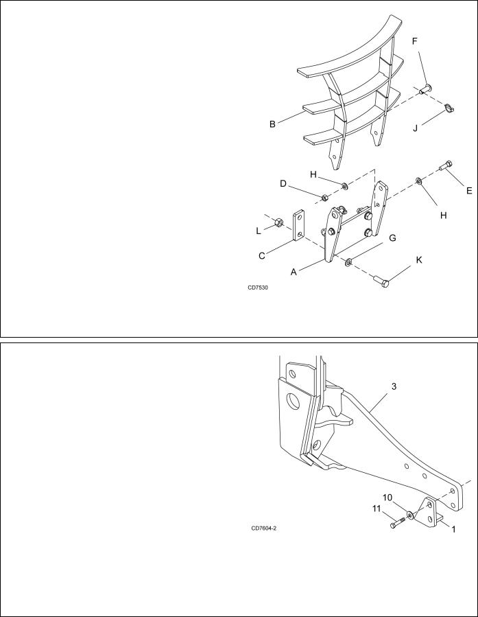
Install Right and Left Mid-Mounts
NOTE: Use an overhead lifting device capable of lifting mount. Slide strap through loader mounting hole and cinch (Figure 1). Mount should be balanced and hang straight.
1.Attach right mount to loader ready bracket using four cap screws (12) and hardened washers (10).
2.Attach right mount (3) to the tractor frame using four cap screws (12) and hardened flat washers (10).
3.Repeat steps to install left mount (4).
NOTE: On some tractor models the fuel tank is very close to the left loader ready bracket and may cause an interference point when cap screws (12) are installed. If interference is possible add a second washer (10) to each of the four cap screws.
4.Torque cap screws (12) to 374 lbs-ft (507 N-m). Check bolt size and torque loader ready bracket hardware to specifications listed on page 16.
3.1028920 Right Mount
4.1028921 Left mount
10.1006371 3/4 Hardened flat washer, extra thk
12.1030297 M20 x 2.5P x 65 mm HHCS CL10.9
Figure 2. Right Mount Installed
Figure 1. Lift Strap Location
Figure 3. Right Mount Installation
MAN0788 (1/16/2009) |
Mount Installation 5 |
|
|
Install Optional Grill Guard
1.Attach grill guard support bracket (A) to the front of the tractor using four cap screws (K), hardened flat washers (G), two spacers (C) and hex nuts (L)
2.Attach grill guard (B) to support bracket (A) using two (one per side) cap screw (E), four hardened flat washers (H) and hex nuts (D).
NOTE: Do not overtighten cap screws (E); grill guard must be able to pivot for access to the battery.
3.Rotate grill guard up and secure into position using two clevis pins (F) and lynch pins (J).
4.Torque cap screws (K) to 244 lbs-ft (330 N-m).
A.1028909 Grill guard support bracket
B.1028912 Grill guard
C.1028919 Grill guard spacer
D.230 5/8 NC Hex nut
E.902 5/8 NC x 2 HHCS GR5
F.26299 Clevis pin, 3/4 x 2
G.57798 3/4 Hardened flat washer H. 57817 5/8 Hardened flat washer
J. 304075 Lynch pin, 1/4 |
Figure 4. Grill Guard Installation |
K.307554 M20 x 2.5P x 60 HHCS
L.307913 M20 x 2.5P Hex nut
Install Oscillation Stops (Optional)
Oscillation stops are not required on all tractors. To determine if stops are needed:
●Check tire clearance after loader has been installed.
●Raise front tires off the ground and oscillate front axle up and down, turning the tires in both directions.
●If tires contact loader or loader mount, oscillation stops will be required.
1.Remove the two from cap screws on loader mount. Place oscillation stop over mount and secure using two cap screws (11) and hardened flat washer previously removed.
2.Repeat steps to install oscillation stop on opposite side of tractor.
3.Torque cap screws (11) to 374 lbs-ft (507 N-m).
1.1026397 Left oscillation stop
2.1026398 Right oscillation stop
Figure 5. Right Oscillation Stop Installation
10.1006371 3/4 Hardened flat washer, extra thk
11.1028950 M20 x 2.5P x 80 mm HHCS CL10.9
(used with oscillation stops only)
6 Mount Installation |
MAN0788 (1/16/2009) |
|
|
 Loading...