


SNOWBLOWER
SS84-2
SS96-2
SS108-2
MAN0884 ( 2/20/2012)

 OPERATOR'S MANUAL

TO THE DEALER:
Assembly and proper installation of this product is the responsibility of the Woods® dealer. Read manual instructions and safety rules. Make sure all items on the Dealer’s Pre-Delivery and Delivery Check Lists in the Operator’s Manual are completed before releasing equipment to the owner.
The dealer must complete the online Product Registration form at the Woods Dealer Website which certifies that all Dealer Check List items have been completed. Dealers can register all Woods product at dealer.WoodsEquipment.com under Product Registration.
Failure to register the product does not diminish customer’s warranty rights.
TO THE OWNER:
Read this manual before operating your Woods equipment. The information presented will prepare you to do a better and safer job. Keep this manual handy for ready reference. Require all operators to read this manual carefully and become acquainted with all adjustment and operating procedures before attempting to operate. Replacement manuals can be obtained from your dealer. To locate your nearest dealer, check the Dealer Locator at www.WoodsEquipment.com, or in the United States and Canada call 1-800-319-6637.
The equipment you have purchased has been carefully engineered and manufactured to provide dependable and satisfactory use. Like all mechanical products, it will require cleaning and upkeep. Lubricate the unit as specified. Observe all safety information in this manual and safety decals on the equipment.
For service, your authorized Woods dealer has trained mechanics, genuine Woods service parts, and the necessary tools and equipment to handle all your needs.
Use only genuine Woods service parts. Substitute parts will void the warranty and may not meet standards required for safe and satisfactory operation. Record the model number and serial number of your equipment in the spaces provided:
Model: _______________________________ |
Date of Purchase: _____________________ |
Serial Number: (see Safety Decal section for location) ____________________________________
Provide this information to your dealer to obtain correct repair parts.
Throughout this manual, the term NOTICE is used to indicate that failure to observe can cause damage to equipment. The terms CAUTION, WARNING, and DANGER are used in conjunction with the Safety-Alert Symbol (a triangle with an exclamation mark) to indicate the degree of hazard for items of personal safety.
|
|
|
|
|
|
|
|
|
|
|
|
|
|
|
|
|
|
|
2 Introduction |
Gen’l (Rev. 12/5/2011) |
|||
|
|
|
|
|
|
TABLE OF CONTENTS
INTRODUCTION . . . . . . . . . . . . . . . . . . . . . . . . . . . . . . . . . . . . . . . . . . . . . . 2 SPECIFICATIONS . . . . . . . . . . . . . . . . . . . . . . . . . . . . . . . . . . . . . . . . . . . . . 4 GENERAL INFORMATION . . . . . . . . . . . . . . . . . . . . . . . . . . . . . . . . . . . . . . 4 SAFETY RULES . . . . . . . . . . . . . . . . . . . . . . . . . . . . . . . . . . . . . . . . . . . . . . 5 SAFETY DECALS . . . . . . . . . . . . . . . . . . . . . . . . . . . . . . . . . . . . . . . . . . . . . 8 OPERATION . . . . . . . . . . . . . . . . . . . . . . . . . . . . . . . . . . . . . . . . . . . . . . . . 10 OWNER SERVICE . . . . . . . . . . . . . . . . . . . . . . . . . . . . . . . . . . . . . . . . . . . 17 TROUBLE SHOOTING . . . . . . . . . . . . . . . . . . . . . . . . . . . . . . . . . . . . . . . . 21 ASSEMBLY INSTRUCTIONS . . . . . . . . . . . . . . . . . . . . . . . . . . . . . . . . . . . 22 DEALER CHECK LIST . . . . . . . . . . . . . . . . . . . . . . . . . . . . . . . . . . . . . . . . 24 INDEX TO PARTS LISTS . . . . . . . . . . . . . . . . . . . . . . . . . . . . . . . . . . . . . . 25 BOLT TORQUE CHART . . . . . . . . . . . . . . . . . . . . . . . . . . . . . . . . . . . . . . . 33 BOLT SIZE CHART & ABBREVIATIONS . . . . . . . . . . . . . . . . . . . . . . . . . . 34 PRODUCT WARRANTY . . . . . . . . . . . . . . . . . . . . . . . . . . . Inside Back Cover REPLACEMENT PARTS WARRANTY . . . . . . . . . . . . . . . . . . . . . Back Cover
(Rev. 2/20/2012)
MAN0884 (08/15/2011)
Introduction 3

SPECIFICATIONS
Width Of Cut: . . . . . . . . . . . . . . . . . . SS84-2 . . . . . . . . . . . . . . . . . . . . . .84" SS96-2 . . . . . . . . . . . . . . . . . . . . . .96" SS108-2 . . . . . . . . . . . . . . . . . . . .108"
Cutting Height . . . . . . . . . . . . . . . . . . . . . . . . . . . . . . . . . . . . . . . . . . . . . . .38"
Number of Augers. . . . . . . . . . . . . . . . . . .1 (SS84-2), 2 (SS96-2 & SS108-2)
Auger Diameter. . . . . . . . . . . . . . . . . . . . . . . . . . . . . . . . . . . . . . . . . . . . . .15"
Fan Diameter . . . . . . . . . . . . . . . . . . . . . . . . . . . . . . . . . . . . . . . . . . . . . . .34"
Auger Flighting Thickness . . . . . . . . . . . . . . . . . . . . . . . . . . . . . . . .5/16" x 3"
Roller Chain . . . . . . . . . . . . . . . . . . . . . . . . . . . . . . . . . . . . . . . . . . . . . . . #60
Chute Rotation . . . . . . . . . . . . . . . . . . . . . . . . . . . . . . . . . . . . . . . . . 200 Deg.
Chute Length . . . . . . . . . . . . . . . . . . . . . . . . . . . . . . . . . . . . . . . . . . . . . . .34"
Operating Weight . . . . . . . . . . . . . . . SS84-2 . . . . . . . . . . . . . . . . . . 1395lbs
SS96-2 . . . . . . . . . . . . . . . . . . 1482lbs
SS108-2 . . . . . . . . . . . . . . . . . 1614lbs
PTO Horsepower Requirement: . . . . SS84-2 . . . . . . . . . . . . . . . 60 - 80 H.P.
SS96-2 . . . . . . . . . . . . . . 80 - 125 H.P.
SS108-2 . . . . . . . . . . . . 125 - 200 H.P.
Tractor Hitch . . . . . . . . . . . . . . . . . . . . . . . . . . . . . . . . . . . . . . . CAT2 & CAT3
PTO Input . . . . . . . . . . . . . . . . . . . . . SS84-2 . . . . . . . . . . . . . . . . . 540 RPM
SS96-2 & SS108-2 . 540 or 1000 RPM
Auger Speed . . . . . . . . . . . . . . . . . . . . . . . . . . . . . . . . . . . . . . . . . . . 176 RPM
Gearbox Oil Capacity . . . . . . . . . . . . . . . . . . . . . . . . . . 1.27 Qt SAE 80W-90
GENERAL INFORMATION

Some illustrations in this manual show the equipment with safety shields removed to provide a better view. This equipment should never be operated with any necessary safety shielding removed.
The purpose of this manual is to assist you in operating and maintaining your snowblower. Read it carefully. It furnishes information and instructions that will help you achieve years of dependable performance. These instructions have been compiled from extensive field experience and engineering data. Some information
may be general in nature due to unknown and varying operating conditions. However, through experience and these instructions, you should be able to develop procedures suitable to your particular situation.
The illustrations and data used in this manual were current at the time of printing, but due to possible inline production changes, your machine may vary slightly in detail. We reserve the right to redesign and change the machines as may be necessary without notification.
Throughout this manual, references are made to right, left, forward and rearward directions. These are determined by sitting in the tractor operator's seat facing the direction of forward travel.
4 Introduction |
MAN0884 (08/15/2011) |
|

SAFETY RULES
ATTENTION! BECOME ALERT! YOUR SAFETY IS INVOLVED!
Safety is a primary concern in the design and manufacture of our products. Unfortunately, our efforts to provide safe equipment can be wiped out by an operator’s single careless act.
In addition to the design and configuration of equipment, hazard control and accident prevention are dependent upon the awareness, concern, judgement, and proper training of personnel involved in the operation, transport, maintenance and storage of equipment.
It has been said “The best safety device is an informed, careful operator.” We ask you to be that kind of operator.
TRAINING
Safety instructions are important! Read all attachment and power unit manuals; follow all safety rules and safety decal information. (Replacement manuals and safety decals are available from your dealer. To locate your nearest dealer, check the Dealer Locator at www.WoodsEquipment.com, or in the United States and Canada call 1-800-319- 6637.) Failure to follow instructions or safety rules can result in serious injury or death.
If you do not understand any part of this manual and need assistance, see your dealer.
Know your controls and how to stop engine and attachment quickly in an emergency.
Operators must be instructed in and be capable of the safe operation of the equipment, its attachments, and all controls. Do not allow anyone to operate this equipment without proper instructions.
Keep hands and body away from pressurized lines. Use paper or cardboard, not hands or other body parts to check for leaks. Wear safety goggles. Hydraulic fluid under pressure can easily penetrate skin and will cause serious injury or death.
Make sure that all operating and service personnel know that if hydraulic fluid penetrates skin, it must be surgically removed as soon as possible by a doctor familiar with this form of injury or gangrene, serious injury, or death will result. CONTACT A PHYSICIAN IMMEDIATELY IF FLUID ENTERS SKIN OR EYES. DO NOT DELAY.
Never allow children or untrained persons to operate equipment.
PREPARATION
Check that all hardware is properly installed. Always tighten to torque chart specifications unless instructed otherwise in this manual.
Air in hydraulic systems can cause erratic operation and allows loads or equipment components to drop unexpectedly. When connecting equipment or hoses or performing any hydraulic maintenance, purge any air in hydraulic system by operating all hydraulic functions several times. Do this before putting into service or allowing anyone to approach the equipment.
Always wear relatively tight and belted clothing to avoid getting caught in moving parts. Wear sturdy, rough-soled work shoes and protective equipment for eyes, hair, hands, hearing, and head; and respirator or filter mask where appropriate.
Make sure attachment is properly secured, adjusted, and in good operating condition.
Make sure all safety decals are installed. Replace if damaged. (See Safety Decals section for location.)
Make sure shields and guards are properly installed and in good condition. Replace if damaged.
Make sure spring-activated locking pin or collar slides freely and is seated firmly in tractor PTO spline groove.
A minimum 20% of tractor and equipment weight must be on the tractor front wheels when attachments are in transport position. Without this weight, front tractor wheels could raise up resulting in loss of steering. The weight may be attained with front wheel weights, ballast in tires or front tractor weights. Weigh the tractor and equipment. Do not estimate.
Inspect and clear area of stones, branches, or other hard objects that might be thrown, causing injury or damage.
OPERATION
Never place hands or body into discharge chute or auger to unclog. Stored energy can cause auger to quickly rotate when unclogging occurs and cause severe injury or amputation. Stop engine, remove key, disconnect driveline, and carefully unclog, using a sturdy piece of wood.
Keep bystanders away from equipment.
Never direct discharge toward people, animals, or property.
Snowblower_SRs (2/14/2012)
Safety 5

SAFETY RULES
ATTENTION! BECOME ALERT! YOUR SAFETY IS INVOLVED!
Do not operate or transport equipment while under the influence of alcohol or drugs.
Operate only in daylight or good artificial light.
Keep hands, feet, hair, and clothing away from equipment while engine is running. Stay clear of all moving parts.
Always comply with all state and local lighting and marking requirements.
Never allow riders on power unit or attachment.
Always sit in power unit seat when operating controls or starting engine. Securely fasten seat belt, place transmission in neutral, engage brake, and ensure all other controls are disengaged before starting power unit engine.
Operate tractor PTO at RPM listed on safety decal located on fan housing above gearbox. Do not exceed.
Connect PTO driveline directly to power unit PTO shaft. Never use adapter sleeves or adapter shafts. Adapters can cause driveline failures due to incorrect spline or incorrect operating length and can result in personal injury or death.
Do not operate PTO during transport.
Look down and to the rear and make sure area is clear before operating in reverse.
Do not operate or transport on steep slopes.
Do not stop, start, or change directions suddenly on slopes.
Use extreme care and reduce ground speed on slopes and rough terrain.
Use extreme care when working close to fences, ditches, other obstructions, or on hillsides.
Watch for hidden hazards on the terrain during operation.
Watch for traffic when operating near or crossing roadways.
Stop power unit and equipment immediately upon striking an obstruction. Turn off engine, remove key, inspect, and repair any damage before resuming operation.
Before dismounting power unit or performing any service or maintenance, follow these steps: disengage power to equipment, lower the 3-point hitch and all raised components to the ground, operate valve levers to release any hydraulic pressure, set parking brake, stop engine, remove key, and unfasten seat belt.
Before performing any service or maintenance, disconnect driveline from tractor PTO.
MAINTENANCE
Before dismounting power unit or performing any service or maintenance, follow these steps: disengage power to equipment, lower the 3-point hitch and all raised components to the ground, operate valve levers to release any hydraulic pressure, set parking brake, stop engine, remove key, and unfasten seat belt.
Before performing any service or maintenance, disconnect driveline from tractor PTO.
NEVER GO UNDERNEATH EQUIPMENT. Never place any part of the body underneath equipment or between moveable parts even when the engine has been turned off. Hydraulic system leak-down, hydraulic system failures, mechanical failures, or movement of control levers can cause equipment to drop or rotate unexpectedly and cause severe injury or death.
•Service work does not require going underneath implement.
•Read Operator's Manual for service instructions or have service performed by a qualified dealer.
Service and maintenance work not covered in OWNER SERVICE must be done by a qualified dealership. Special skills, tools, and safety procedures may be required. Failure to follow these instructions can result in serious injury or death.
Do not modify or alter or permit anyone else to modify or alter the equipment or any of its components in any way.
Your dealer can supply original equipment hydraulic accessories and repair parts. Substitute parts may not meet original equipment specifications and may be dangerous.
Always wear relatively tight and belted clothing to avoid getting caught in moving parts. Wear sturdy, rough-soled work shoes and protective equipment for eyes, hair, hands, hearing, and head; and respirator or filter mask where appropriate.
Make sure attachment is properly secured, adjusted, and in good operating condition.
Keep all persons away from operator control area while performing adjustments, service, or maintenance.
Tighten all bolts, nuts, and screws to torque chart specifications. Check that all cotter pins are
6 Safety
Snowblower_SRs (2/14/2012)

installed securely to ensure equipment is in a safe condition before putting unit into service.
Make sure all safety decals are installed. Replace if damaged. (See Safety Decals section for location.)
Make sure shields and guards are properly installed and in good condition. Replace if damaged.
Do not disconnect hydraulic lines until engine is stopped, power unit is properly secured, equipment and all components are lowered to the
ground, and system pressure is released by operating all valve control levers.
Use a suitable lifting device of sufficient capacity. Use adequate personnel to handle heavy components.
STORAGE
Block equipment securely for storage.
Keep children and bystanders away from storage area.
Snowblower_SRs (2/14/2012)
Safety 7
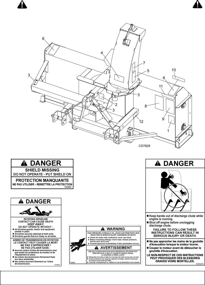
SAFETY & INSTRUCTIONAL DECALS
ATTENTION! BECOME ALERT! YOUR SAFETY IS INVOLVED!
Replace Immediately If Damaged!
3 - 1033602 5 - 1033270
10 - P/N 57123
REAR REFLECTOR - RED
11 - P/N 1002940
FRONT REFLECTOR - AMBER
1 - 1033600
4 - 1033603
8 Safety |
MAN0884 08/15/2011) |
|

SAFETY & INSTRUCTIONAL DECALS
ATTENTION! BECOME ALERT! YOUR SAFETY IS INVOLVED! Replace Immediately If Damaged!
9 - 1033274 |
8 - 1033273 |
6 - 1033271 |
7 - 1033272
2 - 55922
2 - 1033601
BE CAREFUL!
Use a clean, damp cloth to clean safety decals.
Avoid spraying too close to decals when using a pressure washer;
high-pressure water can enter through very small scratches or under 12 - 1033176 edges of decals causing them to peel or come off.
Replacement safety decals can be ordered free from your Woods dealer. To locate your nearest dealer, check the Dealer Locator at www.WoodsEquipment.com, or in the United States and Canada call
1-800-319-6637.
MAN0884 (08/15/2011) |
Safety 9 |
|
|

OPERATION
The operator is responsible for the safe operation of the snowblower. The operator must be properly trained. Operators should be familiar with the tractor, snowblower, and all safety practices before starting operation. Read through safety rules and decals on page 5 through page 9.
Safety instructions are important! Read all attachment and power unit manuals; follow all safety rules and safety decal information. (Replacement manuals and safety decals are available from your dealer. To locate your nearest dealer, check the Dealer Locator at www.WoodsEquipment.com, or in the United States and Canada call 1-800-319- 6637.) Failure to follow instructions or safety rules can result in serious injury or death.
Operators must be instructed in and be capable of the safe operation of the equipment, its attachments, and all controls. Do not allow anyone to operate this equipment without proper instructions.
Power unit must be equipped with ROPS or ROPS cab and seat belt. Keep seat belt securely fastened. Falling off power unit can result in death from being run over or crushed. Keep foldable ROPS system in “locked up” position at all times.
Do not allow bystanders in the area when operating, attaching, removing, assembling, or servicing equipment.
Never allow children or untrained persons to operate equipment.
Never go underneath equipment (lowered to the ground or raised) unless it is properly blocked and secured. Never place any part of the body underneath equipment or between moveable parts even when the engine has been turned off. Hydraulic system leak down, hydraulic system failures, mechanical failures, or movement of control levers can cause equipment to drop or rotate unexpectedly and cause severe injury or death. Follow Operator's Manual instructions for working underneath and blocking requirements or have work done by a qualified dealer.
Keep bystanders away from equipment.
Keep hands, feet, hair, and clothing away from equipment while engine is running. Stay clear of all moving parts.
Never place hands or body into discharge chute or auger to unclog. Stored energy can cause auger to quickly rotate when unclogging occurs and cause severe injury or amputation. Stop engine,
remove key, disconnect driveline, and carefully unclog, using a sturdy piece of wood.
Keep hands and body away from pressurized lines. Use paper or cardboard, not hands or other body parts to check for leaks. Wear safety goggles. Hydraulic fluid under pressure can easily penetrate skin and will cause serious injury or death.
Make sure that all operating and service personnel know that if hydraulic fluid penetrates skin, it must be surgically removed as soon as possible by a doctor familiar with this form of injury or gangrene, serious injury, or death will result. CONTACT A PHYSICIAN IMMEDIATELY IF FLUID ENTERS SKIN OR EYES. DO NOT DELAY.
Before dismounting power unit or performing any service or maintenance, follow these steps: disengage power to equipment, lower the 3-point hitch and all raised components to the ground, operate valve levers to release any hydraulic pressure, set parking brake, stop engine, remove key, and unfasten seat belt.
Make sure spring-activated locking pin or collar slides freely and is seated firmly in tractor PTO spline groove.
Operate tractor PTO at the rpm speed stated in “Specifications” section.
Make sure attachment is properly secured, adjusted, and in good operating condition.
If you do not understand any part of this manual and need assistance, see your dealer.
Always wear relatively tight and belted clothing to avoid getting caught in moving parts. Wear sturdy, rough-soled work shoes and protective equipment for eyes, hair, hands, hearing, and head; and respirator or filter mask where appropriate.
NOTICE
■ Be sure to complete the Pre-Operation Check
List on page 16 prior to operating this Snowblower.
PRINCIPAL COMPONENTS
The snowblower has three main operating components. A 15" diameter auger dislodges the snow and carries it to a central fan. The snow is then discharged by the fan and directed away from the blower through a controllable spout.
10 Operation |
MAN0884 (08/15/2011) |
|
|
The snowblower is mounted on a tractor 3-point hitch and driven by the tractor PTO. A centrally located gearbox directs power to the fan and auger.
TRACTOR REQUIREMENTS
3-Point Hitch
The SS snowblower requires the tractor to be equipped with a Category 2 or 3, three-point hitch.
Hydraulic Circuit
Either closed-center or open-center systems can be used for the hydraulic chute rotator and optional spout control.
Tire Configuration
For best results, the tractor wheels should be set narrower than the cutting width of the snowblower. Wider wheel settings will cause snow to be pulled under the tractor and may require additional passes.
Tractor Stability
A minimum 20% of tractor and equipment weight must be on the tractor front wheels when attachments are in transport position. Without this weight, front tractor wheels could raise up resulting in loss of steering. The weight may be attained with front wheel weights, ballast in tires or front tractor weights. Weigh the tractor and equipment. Do not estimate.
Figure 1. Tractor Stability (Typical)
HITCH ADJUSTMENT
AWARNING
Before putting equipment into service, check and adjust driveline length as instructed in Operator's Manual. Driveline must not bottom out or pull apart throughout the full range of the tractor hitch. Do not operate until driveline length is correct.
Never go underneath equipment (lowered to the ground or raised) unless it is properly blocked and secured. Never place any part of the body underneath equipment or between moveable parts even when the engine has been turned off. Hydraulic system leak down, hydraulic system failures, mechanical failures, or movement of control levers can cause equipment to drop or rotate unexpect-
edly and cause severe injury or death. Follow Operator's Manual instructions for working underneath and blocking requirements or have work done by a qualified dealer.
Keep all persons away from operator control area while performing adjustments, service, or maintenance.
The snowblower has an adjustable hitch for establishing the proper PTO operating geometry. You must perform the following procedure for each tractor or quick hitch used.
Follow the above safety rules and securely block the snowblower with jackstands when taking measurements. Always stand alongside of hitch and never go underneath any raised components. The tractor must be shut off, parking brake set, and key removed each time the operator leaves the tractor seat during this procedure. Refer to Figure 2.
1. Clear the area of all bystanders.
Figure 2. 3-Point Hitch Adjustment Positions
2.The snowblower 3-point hitch arms are adjustable to three operating positions. Assemble the arms in their shortest position (A) and adjust for proper PTO driveline engagement before using. Remove adjustment bolts from snowblower lower arms and top link arm. Slide the arm assembly to the correct mounting hole and install adjustment bolts. Torque bolts to specifications in Bolt Torque Chart on page 32.
3.Attach snowblower to tractor, but do not attach PTO shaft.
4.Move snowblower until tractor PTO and gearbox shafts are the same height. This should be the position requiring the shortest driveline length. Securely block both ends of snowblower housing using jackstands.
5.Measure the distance between the lock groove on tractor PTO shaft and the cross hole in snowblower gearbox shaft. The distance between the groove and cross hole must be greater than 37.5" to provide one inch of compression space in the shaft and prevent bottoming out during use.
6.If the dimension is less than 37.5", the hitch must be extended to mounting hole B. Recheck the
MAN0884 (08/15/2011) |
Operation 11 |
|
|
 Loading...