


MOW’N MACHINETM
FZ23B
FZ28K
Serial Number 1177489 & Up
MAN0875 (Rev. 3/7/2012)

 OPERATOR'S MANUAL

TO THE DEALER:
Assembly and proper installation of this product is the responsibility of the Woods® dealer. Read manual instructions and safety rules. Make sure all items on the Dealer’s Pre-Delivery and Delivery Check Lists in the Operator’s Manual are completed before releasing equipment to the owner.
The dealer must complete the online Product Registration form at the Woods Dealer Website which certifies that all Dealer Check List items have been completed. Dealers can register all Woods product at dealer.WoodsEquipment.com under Product Registration.
Failure to register the product does not diminish customer’s warranty rights.
TO THE OWNER:
Read this manual before operating your Woods equipment. The information presented will prepare you to do a better and safer job. Keep this manual handy for ready reference. Require all operators to read this manual carefully and become acquainted with all adjustment and operating procedures before attempting to operate. Replacement manuals can be obtained from your dealer. To locate your nearest dealer, check the Dealer Locator at www.WoodsEquipment.com, or in the United States and Canada call 1-800-319-6637.
The equipment you have purchased has been carefully engineered and manufactured to provide dependable and satisfactory use. Like all mechanical products, it will require cleaning and upkeep. Lubricate the unit as specified. Observe all safety information in this manual and safety decals on the equipment.
For service, your authorized Woods dealer has trained mechanics, genuine Woods service parts, and the necessary tools and equipment to handle all your needs.
Use only genuine Woods service parts. Substitute parts will void the warranty and may not meet standards required for safe and satisfactory operation. Record the model number and serial number of your equipment in the spaces provided:
Model: _______________________________ |
Date of Purchase: _____________________ |
Serial Number: (see Safety Decal section for location) ____________________________________
Provide this information to your dealer to obtain correct repair parts.
Throughout this manual, the term NOTICE is used to indicate that failure to observe can cause damage to equipment. The terms CAUTION, WARNING, and DANGER are used in conjunction with the Safety-Alert Symbol (a triangle with an exclamation mark) to indicate the degree of hazard for items of personal safety.
|
|
|
|
|
|
|
|
|
|
|
|
|
|
|
|
|
|
|
2 Introduction |
Gen’l (Rev. 12/5/2011) |
|||
|
|
|
|
|
|
TABLE OF CONTENTS
INTRODUCTION . . . . . . . . . . . . . . . . . . . . . . . . . . . . . . . . . . . . . . . . . . . . . . .2 SPECIFICATIONS. . . . . . . . . . . . . . . . . . . . . . . . . . . . . . . . . . . . . . . . . . . . . .4 GENERAL INFORMATION . . . . . . . . . . . . . . . . . . . . . . . . . . . . . . . . . . . . . . .4 SAFETY RULES . . . . . . . . . . . . . . . . . . . . . . . . . . . . . . . . . . . . . . . . . . . . . . .5 SAFETY DECALS . . . . . . . . . . . . . . . . . . . . . . . . . . . . . . . . . . . . . . . . . . . . . .9 OPERATION . . . . . . . . . . . . . . . . . . . . . . . . . . . . . . . . . . . . . . . . . . . . . . . . .11 OWNER SERVICE . . . . . . . . . . . . . . . . . . . . . . . . . . . . . . . . . . . . . . . . . . . .16 DEALER SERVICE . . . . . . . . . . . . . . . . . . . . . . . . . . . . . . . . . . . . . . . . . . . .20 TROUBLE SHOOTING . . . . . . . . . . . . . . . . . . . . . . . . . . . . . . . . . . . . . . . . .21 ASSEMBLY INSTRUCTIONS . . . . . . . . . . . . . . . . . . . . . . . . . . . . . . . . . . . .26 DEALER CHECK LISTS . . . . . . . . . . . . . . . . . . . . . . . . . . . . . . . . . . . . . . . .28 INDEX TO PARTS LISTS . . . . . . . . . . . . . . . . . . . . . . . . . . . . . . . . . . . . . . .29 BOLT TORQUE CHART . . . . . . . . . . . . . . . . . . . . . . . . . . . . . . . . . . . . . . . .50 BOLT SIZE CHART & ABBREVIATIONS . . . . . . . . . . . . . . . . . . . . . . . . . . .51 INDEX . . . . . . . . . . . . . . . . . . . . . . . . . . . . . . . . . . . . . . . . . . . . . . . . . . . . . .52 REPLACEMENT PARTS WARRANTY . . . . . . . . . . . . . . . . . . . . . . . . . . . . 53 PRODUCT WARRANTY . . . . . . . . . . . . . . . . . . . . . . . . . . . . . BACK COVER
 WARNING
The engine exhaust from this product contains chemicals known to the State of California to cause cancer, birth defects or other reproductive harm.
 WARNING
This product contains chemicals, including lead, known to the State of California to cause cancer, and birth defects or other reproductive harm. Wash hands after handling.
!LEA EL INSTRUCTIVO!
Si no lee Ingles, pida ayuda a alguien que si lo lea para que le traduzca las medidas de seguridad.
MAN0875 (2/8/2011) |
Introduction 3 |
|
|

SPECIFICATIONS
Engine: |
FZ23B . . . . . |
Briggs & Stratton Vanguard V-Twin, 4-Cycle, Air Cooled |
|
FZ28K . . . . . |
. . . . . . . . . . . . . . . . . . . .Kawasaki, 4-Cycle, Air Cooled |
Horsepower: FZ23B . . . . . . . . . . . . . . . . . . . . . . . . . . . . . . . . . . . . . . . . . . . . 23 HP
FZ28K . . . . . . . . . . . . . . . . . . . . . . . . . . . . . . . . . . . . . . . . . . . . 28 HP
Fuel Type: . . . . . . . . . . . Gasoline (minimum 85 octane, unleaded recommended)
Standard Tire Size: |
Front . . . . . . . . . . . . . . . . . . . . . . . . . . . |
. 23 x 10.50 - 12 |
|
Rear . . . . . . . . . . . . . . . . . . . . . . . . . . . |
15 x 6.00 - 6 Rib |
Recommended Air Pressure:
Front . . . . . . . . . . . . . . . . . . . . . . . . . . . . . . . . . . . 12 psi Rear . . . . . . . . . . . . . . . . . . . . . . . . . . . Maximum 18 psi
Fuel Tank Capacity: . . . . . . . . . . . . . . . . . . . . . . . . . . . . . . . . . . . . . . . .8.5 Gallons
Power Unit Dimensions: Width . . . . . . . . . . . . . . . . . . . . . . . . . . . . . . . . . . . . . 50" Over all Length . . . . . . . . . . . . . . . . . . . . . . . . . . . . . 84" Weight . . . . . . . . . . . . . . . . . . . . . . . . . . . . . . . . 1000 lbs
Recommended Mowers:
FZ23B . . . . . . . . . . . . . . . . . . . . . . . . . . . . . . . . .54", 61"
FZ28K . . . . . . . . . . . . . . . . . . . . . . . . . . . . . . . . .54", 61"
GENERAL INFORMATION

■ Some illustrations in this manual show the mower with safety shields removed to provide a better view. The Mow’n Machine should never be operated with any safety shielding removed.
The purpose of this manual is to assist you in operating and maintaining your Mow’n Machine. Read it carefully. It furnishes information and instructions that will help you achieve years of dependable performance. These instructions have been compiled from extensive field experience and engineering data. Some information may be general in nature due to unknown and varying
operating conditions. However, through experience and these instructions, you should be able to develop procedures suitable to your particular situation.
The illustrations and data used in this manual were current at the time of printing but, due to possible inline production changes, your machine may vary slightly in detail. We reserve the right to redesign and change the machines as may be necessary without notification.
Throughout this manual, references are made to right and left directions. These are determined by standing behind the equipment, facing the direction of forward travel.
4 Introduction |
MAN0875 (2/8/2011) |
|

SAFETY RULES
ATTENTION! BECOME ALERT! YOUR SAFETY IS INVOLVED!
Safety is a primary concern in the design and manufacture of our products. Unfortunately, our efforts to provide safe equipment can be wiped out by an operator’s single careless act.
In addition to the design and configuration of equipment, hazard control and accident prevention are dependent upon the awareness, concern, judgement, and proper training of personnel involved in the operation, transport, maintenance, and storage of equipment.
It has been said, “The best safety device is an informed, careful operator.” We ask you to be that kind of operator.
TRAINING
Safety instructions are important! Read all attachment and power unit manuals; follow all safety rules and safety decal information. (Replacement manuals and safety decals are available from your dealer. To locate your nearest dealer, check the Dealer Locator at www.WoodsEquipment.com, or in the United States and Canada call 1-800-319- 6637.) Failure to follow instructions or safety rules can result in serious injury or death.
Data indicates that those operators age 60 years and above are involved in a large percentage of riding mower-related injuries. Those operators should evaluate their ability to operate the riding mower safely enough to protect themselves and others from injury.
If you do not understand any part of this manual and need assistance, see your dealer.
Know your controls and how to stop engine and attachment quickly in an emergency.
Operators must be instructed in and be capable of the safe operation of the equipment, its attachments, and all controls. Do not allow anyone to operate this equipment without proper instructions.
Never allow children or untrained persons to operate equipment.
PREPARATION
Check that all hardware is properly installed. Always tighten to torque chart specifications unless instructed otherwise in this manual.
Always wear relatively tight and belted clothing to avoid getting caught in moving parts. Wear sturdy, rough-soled work shoes and protective
equipment for eyes, hair, hands, hearing, and head; and respirator or filter mask where appropriate.
Make sure attachment is properly secured, adjusted, and in good operating condition.
Make sure the driveline spring-activated locking collar slides freely and is seated firmly in power unit PTO groove. Make sure the set screws securely attach driveline to the attachment gearbox shaft.
The safety interlock system was installed for your protection. Do not disconnect, disable, override, or execute any action that would cause this system to malfunction. If malfunction occurs, stop all operation and contact dealer for repair.
Remove accumulated debris from this equipment, power unit, and engine to avoid fire hazard.
Keep children out of the mowing area and under the watchful care of a responsible adult other than the operator.
Make sure all safety decals are installed. Replace if damaged. (See Safety Decals section for location.)
Make sure shields and guards are properly installed and in good condition. Replace if damaged.
Be sure either the discharge chute, mulching end cap, or complete vacuum attachment is installed and in good condition. Replace if damaged.
When using weight transfer system, correct counterweight must be used to maintain stability. See counterweight chart in power unit manual or contact dealer.
When equipped with ROPS, total vehicle weight with all equipment, ballast, and operator must not exceed 2,590 lbs.
Inspect and clear area of stones, branches, or other hard objects that might be thrown, causing injury or damage.
Do not mow on wet grass.
While fueling, extinguish all cigarettes, cigars, pipes, and other sources of ignition.
Never fuel the machine indoors.
Never fill fuel containers inside a vehicle or a truck or trailer bed with a plastic liner. Always place container on the ground away from the vehicle before filling.
(Safety Rules continued on next page)
MM F-Series (Rev. 8/1/2008)
Safety 5

SAFETY RULES
ATTENTION! BECOME ALERT! YOUR SAFETY IS INVOLVED!
(Safety Rules continued from previous page)
Remove gas-powered equipment from the truck or trailer and refuel on the ground. If this is not possible, then refuel such equipment on a trailer with a portable container, rather than from a gasoline dispenser nozzle.
Keep the nozzle in contact with the rim of the fuel tank opening at all times until fueling is complete. Do not use a nozzle lock-open device.
If fuel is spilled on clothing, change clothing immediately.
Never over-fill tank. Replace gas cap and tighten securely.
Handle fuel carefully; it is highly flammable. Always use an approved container. Never remove fuel cap or add fuel while engine is running. Allow engine to cool before refueling. Wipe up all spilled fuel before starting engine.
TRANSPORTATION
Use extra care when loading or unloading the machine onto a trailer or truck.
Do not operate or transport on steep slopes.
Do not operate or transport equipment while under the influence of alcohol or drugs.
Transport power unit facing rearward when equipped with a sunshade.
OPERATION
Keep bystanders away from equipment.
Keep children out of the mowing area and under the watchful care of a responsible adult other than the operator.
Make sure people and objects are clear of attachment and discharge area before engaging PTO.
Be alert and turn machine off if a child enters the mowing area.
Before and while backing, look behind and down for children.
Never direct discharge toward people, animals, or property.
Do not operate or transport equipment while under the influence of alcohol or drugs.
Operate only in daylight or good artificial light.
Keep hands, feet, hair, and clothing away from equipment while engine is running. Stay clear of all moving parts.
When improperly operated, power unit can roll over or upset. Use of rollover protective structure (ROPS) with seat belt securely fastened will reduce the possibility of injury or death if rollover or upset occurs.
Use care when operating with ROPS or sunshade around shrubs, trees or other objects that can become entangled with power unit.
Use extreme care when approaching blind corners, shrubs, trees, or other objects that may block your vision.
Always comply with all state and local lighting and marking requirements.
Never allow riders on power unit or attachment.
Start engine from operator's seat after disengaging power unit PTO and placing steering levers in neutral.
Look down and to the rear and make sure area is clear before operating in reverse.
Do not mow in reverse unless absolutely necessary.
Slow down before turning.
Do not operate on slopes greater than 15 degrees (27% grade).
Mow up and down slopes, not across.
If the tires lose traction on a slope, disengage the blade(s) and proceed slowly straight down the slope.
Do not stop, start, or change directions suddenly on slopes.
Do not make sudden changes in speed or direction which could cause the machine to roll over.
Use extreme care and reduce ground speed on slopes and rough terrain.
Installation of a grasscatcher assembly will reduce the stability and maneuverability of the Mow'n Machine when operating on sloping terrain.
Do not tow a trailer over 200 lbs. Do not tow a trailer or add power unit ballast with a combined weight over 200 lbs. Too much weight can cause loss of traction or stability on a slope. It can also reduce parking brake ability. Too much weight will shorten the hydraulic system life. Never tow a trailer with a grass collection system attached to the power unit.
6 Safety
MM F-Series (Rev. 8/1/2008

SAFETY RULES
ATTENTION! BECOME ALERT! YOUR SAFETY IS INVOLVED!
Watch for hidden hazards on the terrain during operation.
Watch for traffic when operating near or crossing roadways.
Uneven terrain could overturn the machine.
Do not try to stabilize the machine by putting your foot on the ground.
Do not mow near drop-offs, ditches, or embankments. The machine could suddenly roll over if a wheel goes over the edge or if the edge caves in.
Stop power unit and equipment immediately upon striking an obstruction. Turn off engine, remove key, inspect, and repair any damage before resuming operation.
Do not drive or operate mower in tilt-up position. Power unit stability is not adequate and resulting loads can damage or cause failure of tilt-up mechanism.
Never leave a running machine unattended.
Moving steering levers rapidly from forward to reverse or reverse to forward could cause loss of control.
Do not operate power unit with attachment removed. Attachment is required for power unit stability.
Before attempting to unplug vacuum hoses, disengage PTO, stop power unit, and remove key.
MAINTENANCE
Before dismounting power unit, follow these steps: lower attachment to ground, shut off PTO, set parking brake, shut off engine, position steering levers to neutral swing-out position, and remove key.
When using a sunshade and lifting hood for maintenance, use caution around pinch points.
Before attempting to unplug vacuum hoses, disengage PTO, stop power unit, and remove key.
Before performing any service or maintenance, lower attachment to ground, turn off power unit engine, remove key, and disconnect battery ground cable (negative -).
Before working underneath, read manual instructions, securely block up, and check stability. Secure blocking prevents equipment from dropping due to hydraulic leak down, hydraulic system failure, or mechanical component failure.
Do not modify or alter or permit anyone else to modify or alter the equipment or any of its components in any way.
Do not work on mower in tilt-up position unless lock-up mechanism is in good condition. Replace if damaged.
Always wear relatively tight and belted clothing to avoid getting caught in moving parts. Wear sturdy, rough-soled work shoes and protective equipment for eyes, hair, hands, hearing, and head; and respirator or filter mask where appropriate
Make sure attachment is properly secured, adjusted, and in good operating condition.
Do not put Mow’n Machine into service unless clutch is working properly. When the engine is at full throttle, PTO-driven accessories must stop within five seconds after the PTO switch is turned to “OFF.” See your dealer for replacement clutches.
Keep all persons away from operator control area while performing adjustments, service, or maintenance.
Do not remove radiator cap while engine is hot.
Do not change engine governor settings or overspeed engine.
Frequently check blades. They should be sharp, free of nicks and cracks, and securely fastened.
Do not handle blades with bare hands. Careless or improper handling may result in serious injury.
Your dealer can supply genuine replacement blades. Substitute blades may not meet original equipment specifications and may be dangerous.
Tighten all bolts, nuts, and screws to torque chart specifications. Check that all cotter pins are installed securely to ensure equipment is in a safe condition before putting unit into service.
Use care to prevent battery acid from contacting skin.
Make sure all safety decals are installed. Replace if damaged. (See Safety Decals section for location.)
Make sure shields and guards are properly installed and in good condition. Replace if damaged.
(Safety Rules continued on next page)
MM F-Series (Rev. 8/1/2008)
Safety 7

SAFETY RULES
ATTENTION! BECOME ALERT! YOUR SAFETY IS INVOLVED!
(Safety Rules continued from previous page)
Battery posts, terminals, wiring insulation, and related accessories contain lead and lead compounds, chemicals known to the State of California to cause cancer and birth defects or other reproductive harm. WASH HANDS AFTER HANDLING.
STORAGE
Keep children and bystanders away from storage area.
Never store equipment where fuel or fumes could reach an open flame or spark. Allow engine to cool before storing in an enclosure.
Never store the machine or fuel container near an open flame, spark or pilot light such as on a water heater or other appliance.
Do not run engine indoors. Exhaust gases contain carbon monoxide, an odorless and deadly poison.
Remove key and store in a secure location to prevent unauthorized persons from operating equipment.
8 Safety
MM F-Series (Rev. 8/1/2008
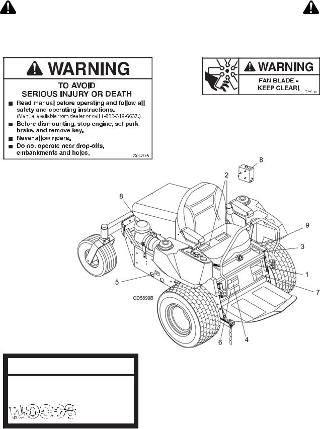
SAFETY & INSTRUCTIONAL DECALS
ATTENTION! BECOME ALERT! YOUR SAFETY IS INVOLVED!
Replace Immediately If Damaged!
1 – 72407 |
2 – 72404 |
3 – SERIAL NUMBER PLATE
MODEL NO.
SERIAL NO.
|
|
|
|
|
|
|
|
|
|
|
(Safety Decals continued on next page) |
|
|
|
|
|
|
|
|
|
|
|
|
|
|
|
|
|
|
|
|
|
|
|
|
|
|
|
|
|
|
|
|
|
|
|
|
|
|
|
|
|
|
|
|
|
|
|
|
|
|
|
|
|
|
|
|
|
|
|
|
|
|
|
|
|
|
|
|
|
|
|
|
|
|
|
|
|
|
|
|
|
|
|
|
MAN0875 (2/8/2011) |
Safety 9 |
||||||||||
|
|
|
|
|
|
|
|
|
|
|
|

SAFETY & INSTRUCTIONAL DECALS
ATTENTION! BECOME ALERT! YOUR SAFETY IS INVOLVED!
Replace Immediately If Damaged!
(Safety Decals continued from previous page)
4 – 72408 |
5 – 72406 |
6 – 70376
7 – 72405 |
BE CAREFUL!
8 - 07754100
07754100
9 - 72801
Use a clean, damp cloth to clean safety decals. Avoid spraying too close to decals when using a pressure washer; high-pressure water can enter through very small scratches or under edges of decals causing them to peel or come off. Replacement safety decals can be ordered free from your Woods dealer, or in the United States and Canada call 1-800-319-6637.
10 Safety |
MAN0875 (2/8/2011) |
|
|
OPERATION
The operator is responsible for the safe operation of this Mow’n Machine. The operator must be properly trained. Operators should be familiar with the power unit, all attachments that will be used, and all safety practices before starting operation. Read the safety rules and safety decals on page 5 through page 10.

Operators must be instructed in and be capable of the safe operation of the equipment, its attachments, and all controls. Do not allow anyone to operate this equipment without proper instructions.
Do not operate power unit with attachment removed. Attachment is required for power unit stability.
Never direct discharge toward people, animals, or property.
Moving steering levers rapidly from forward to reverse or reverse to forward could cause loss of control.
 CAUTION
Start engine from operator's seat after disengaging power unit PTO and placing steering levers in neutral.
Stop power unit and equipment immediately upon striking an obstruction. Turn off engine, remove key, inspect, and repair any damage before resuming operation.
CONTROLS AND SWITCHES

Know your controls and how to stop engine and attachment quickly in an emergency.
The Control and Indicator console is located on the right fuel tank for FZ23B and FZ28K models. This console contains controls needed to operate this unit. PTO switch (2) is used to engage attachments: pull up to engage, push down to disengage.
Deck Height/Power Tilt™
Adjustment Switch
The deck height and Power Tilt™ switch is used with MXT or MX decks equipped with the Power Tilt™ Kit. Push the toggle switch forward to raise the deck and pull back to lower the deck to the desired cutting height. For Power Tilt operation, pull back and hold the
toggle switch to lower the deck and cycle through to the tilt position. Release switch when deck reaches maximum tilt position. To lower the deck, push and hold toggle switch until it cycles to the desired cutting height. NOTE: Power Tilt™ feature must not be used when sitting in the seat.
1. |
Console decal |
6. |
Hour meter |
2. |
PTO switch |
7. |
Throttle control |
3. |
Oil light |
8. |
Choke |
4. |
Brake light |
9. |
Tilt deck switch |
5. |
Ignition switch |
|
|
Figure 1. Console Control Locations
Hour Meter
The hour meter is programmed to alert the operator at various service intervals. The change oil light will flash at 20 hours (initial break in) and every 100 hours after. The light will flash for a period of 4 hours (alternating between hours & change oil) and then resume normal mode. The hour glass will flash every second indicating that it’s in running mode.
|
Service Intervals |
|
|
20 hrs |
Engine oil change (break in) |
100 hrs |
Engine oil change & filter |
500 hrs |
Hydraulic oil change & filter (see |
|
hydraulic transmission - change |
|
oil & filter, page 18.) |
|
|
Brake Lights
The brake light indicates when the brake is engaged. To ensure light is operating properly, engage parking brake and turn ignition key switch to the “ON” position. Control panel brake light (4) should be on.
Safety Switch System
Several safety switches are incorporated in the unit’s design to prevent it from being started out of NEUTRAL (handles pivoted outward) or with PTO engaged.
MAN0875 (2/8/2011) |
Operation 11 |
|
|

The PTO control must be in the “OFF” position and the steering handles in the NEUTRAL position before unit can be started.
A safety switch behind the operator’s seat will cause the engine to stop if the operator leaves the seat with the PTO or steering handles engaged. The engine will also stop if the steering handles are moved from NEUTRAL while the parking brake is engaged or if the deck jumper wire is not connected to the wire harness or the deck safety switch is disengaged.
STARTING ENGINE

Do not run engine indoors. Exhaust gases contain carbon monoxide, an odorless and deadly poison.
To enhance starter life, use short starting cycles not exceeding 10 seconds. If engine does not start within 10 seconds, stop cranking for 30 seconds; then repeat starting procedures.
1.Position yourself on the power unit seat.
2.Set parking brake.
3.Place steering control handles in the NEUTRAL position (pivoted outward).
4.Place PTO switch in the “OFF” position (down).
5.Place throttle approximately 1/3 open.
6.Turn key to “START”.
7.Ensure that the alternator and oil pressure lights are off.
8.Warm up engine several minutes at medium throttle.
NOTE: Choke as necessary to start. When engine starts, release key immediately. Pull choke gradually back until choke is off and engine is running smoothly.
NOTE: Allow engine a warm-up period regardless of the season. Loading a cold engine will shorten its life.
Cold Weather Starting Tips
1.Use proper oil grade for temperature expected. (Refer to engine manual for oil grade.)
2.Set throttle half way open.
3.A warm battery has better starting capacity than a cold one.
4.Use fresh fuel, it is better for starting than leftover fuel.
STARTING MOWER OR ATTACHMENT

Make sure people and objects are clear of attachment and discharge area before engaging PTO.
NOTICE
■ Never engage PTO if the mower blades are plugged with grass or other material. This may cause damage to the electric clutch.
1.With engine running, position throttle at half speed.
2.Engage PTO by pulling up on the PTO switch.
3.Move throttle to full speed and begin operation.
NOTE: Starting attachment at lower engine speed will help prolong the life of the clutch and transmission components.
Stopping Mower or Attachment
Push down on PTO switch.
NOTE: If attachment does not stop in five seconds, the unit requires service.
PRACTICE OPERATION

Never allow children or untrained persons to operate equipment.
Operating this unit is not difficult once you are familiar with the use of the controls. Equip the power unit with the attachment you will be using and practice in a flat open area at half throttle setting until you are comfortable with the controls.
Do not operate attachment until you become proficient with controls.
Uneven Terrain Operation

Do not operate on slopes greater than 15 degrees (27% grade).
Do not stop, start, or change directions suddenly on slopes.
Use extreme care and reduce ground speed on slopes and rough terrain.
12 Operation |
MAN0875 (2/8/2011) |
|
|

Watch for hidden hazards on the terrain during operation.
Practice steering maneuvers at half throttle.
STEERING HANDLE OPERATION

Moving steering levers rapidly from forward to reverse or reverse to forward could cause loss of control.
Do not operate power unit with attachment removed. Attachment is required for power unit stability.
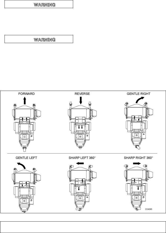
NOTE: Speed and direction are controlled with steering handles. Pushing handles forward will move power unit forward. Pulling handles to the rear will move the power unit in reverse. The further forward or rearward
the steering handles are moved, the faster the machine will move.
Steering Handle Positions
NOTICE
■ If you become confused during operation, return both handles to the center NEUTRAL position and the power unit will stop.
Forward |
Both handles forward |
Reverse |
Both handles rearward |
Gentle Right |
Left handle further forward than right |
Gentle Left |
Right handle further forward than left |
360° Left |
Left full rearward / right full forward |
360° Right |
Right full rearward / left full forward |
NOTE: Moving one handle forward with the other handle in NEUTRAL will also result in a 360-degree circle. However this will cause one drive wheel to dig into the turf and should be avoided.
Figure 2. Steering Handle Operation
(Rev. 3/7/2012)
MAN0875 (2/8/2011)
Operation 13
STOPPING ENGINE
 CAUTION
Remove key and store in a secure location to prevent unauthorized persons from operating equipment.
1.Place steering handles in the NEUTRAL position and set parking brake.
2.Move throttle to 1/3 setting.
3.Allow engine to idle for several minutes.
4.Turn key to OFF position and remove.
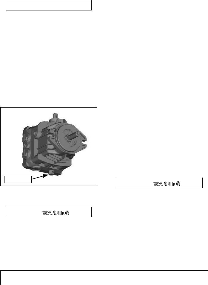
MOVING DISABLED POWER UNIT
Manually move disabled power unit by following these steps.
1.Locate dump valve on bottom of both hydraulic pumps.
2.Turn hex head two full revolutions counterclockwise to open valve, using a 5/8 wrench.
DP2
DUMP VALVE
Figure 3. Left Pump Dump Valve
WEIGHT TRANSFER SYSTEM

■ When using weight transfer system, correct counterweight must be used to maintain stability. See counterweight chart Figure 4 or contact dealer.
The weight transfer is designed to place an additional load on the drive wheels, providing additional traction.
1.Attach mower to power unit and set to desired cutting height.
2.Torque bolt on both sides to 35 lbs-in.
NOTE: Counterweight is needed to provide adequate stability. Refer to the chart to determine your power unit/mower combination, and the amount of counterweight required.
Counterweights are not required when power unit is equipped with a grass catcher system.
|
|
|
With |
|
|
Mower |
FZ23B |
With |
ROPS & |
Grass |
|
FZ28K |
ROPS |
Sun |
Catcher |
||
|
|||||
|
|
|
Shade |
|
|
|
|
|
|
|
|
|
|
|
|
|
|
54" Deck |
50 |
100 |
150 |
0 |
|
61" Deck |
100 |
100 |
150 |
0 |
|
Snow Thrower |
100 |
100 |
150 |
N/A |
|
Dozer Blade |
100 |
100 |
150 |
N/A |
|
60" Sweeper |
150 |
150 |
200* |
N/A |
|
|
|
|
|
|
Figure 4. Counterweight Requirement Chart
* - For additional weight use two 73683 counterweights and one 78025 counterweight cover mounted behind the engine. See page 44 for parts list and diagram.

Do not tow a trailer over 200 lbs. Do not tow a trailer or add power unit ballast with a combined weight over 200 lbs. Too much weight can cause loss of traction or stability on a slope. It can also reduce parking brake ability. Too much weight will shorten the hydraulic system life. Never tow a trailer with a grass collection system attached to the power unit.
14 Operation
(Rev. 8/1/2008)
MAN0875 (2/8/2011)

OWNER PRE-OPERATION CHECK LIST
(OWNER'S RESPONSIBILITY)
___ Review and follow all safety rules and safety decal instructions on pages 5 through 10.
___ Check that all safety decals are installed and in good condition. Replace if damaged.
___ Check to make sure all shields and guards are properly installed and in good condition. Be sure that either the discharge shield or complete vacuum attachment is installed.
___ Check that all hardware and cotter pins are properly installed and secured.
___ Check that equipment is properly and securely attached to power unit.
___ Make sure driveline spring-activated locking pin or collar slides freely and is seated firmly in power unit PTO spline groove and in gearbox spline groove.
___ Check for grass wrap on PTO shaft. When mowing long grass, remove key and check for grass wrap around PTO shaft every 30 minutes of operation.
___ Check to be sure engine is free of dirt and debris. Pay particular attention to the cooling fins, governor parts and muffler.
___ Do not allow riders.
___ Inspect area and remove stones, branches or other hard objects that might be thrown, causing injury or damage.
___ Clean air intake screen. Check air cleaner; service if necessary.
___ Clean area around oil fill dipstick. Remove dipstick and check to be sure oil is in operating range (between marks on dipstick). Add oil if necessary but Do Not Overfill. Install Dipstick assembly firmly until cap bottoms out on tube. Dipstick assembly must always be secured into fill tube when engine is running.
___ Check all lubrication points and grease as
|
instructed in the lubrication information, page 16. |
___ |
Check hydrostatic fluid level (refer to Owner Ser- |
|
vice section). Check to be sure cooling fins on |
|
hydrostat are clean. |
___ |
Perform a functional check of the safety interlock |
|
system each time you operate the unit. Place |
|
both steering levers outward, start engine, |
|
engage PTO and then rise up out of the seat; the |
|
engine should die. If it does not, do not operate |
|
unit until the safety interlock system has been |
|
repaired and operates properly. |
|
|
MAN0875 (2/8/2011) |
Operation 15 |
|
|

OWNER SERVICE

Before performing any service or maintenance, lower attachment to ground, turn off power unit engine, remove key, and disconnect battery ground cable (negative -).
Before working underneath, read manual instructions, securely block up, and check stability. Secure blocking prevents equipment from dropping due to hydraulic leak down, hydraulic system failure, or mechanical component failure.
Keep all persons away from operator control area while performing adjustments, service, or maintenance.
 CAUTION
Always wear relatively tight and belted clothing to avoid getting caught in moving parts. Wear sturdy, rough-soled work shoes and protective equipment for eyes, hair, hands, hearing, and head; and respirator or filter mask where appropriate.
SERVICE ENGINE
NOTE: Follow engine manufacturer recommendations in engine manual.
Check Engine Oil Level
NOTE: Never attempt to check oil level while engine is running. Serious injury or damage to equipment could result.
1.Park power unit on a level surface.
2.Stop engine and clean off dirt and dust from around dipstick.
3.Remove dipstick, check oil level. Oil level should be between marks on dipstick.
4.Add oil as necessary. See engine owner’s manual for specifications.
Change Engine Oil
NOTICE
■ Use care to prevent hot oil from contacting bare skin.
1.Run engine to allow oil to become hot. This will ensure that most foreign materials are in suspension and will be flushed out with the oil.
2.Remove drain plug and drain crankcase.
3.Remove oil filter.
4.Install new oil filter.
5.Install drain plug and add oil.
NOTE: Refer to the engine manual for oil specifications, capacity, service rating, and proper grade.
LUBRICATION INFORMATION
1.Do not let excess grease collect on or around parts, particularly when operating in sandy areas.
2.See Figure 5 for lubrication points and frequency or lubrication based on normal operating conditions. Severe or unusual conditions may require more frequent lubrication.
3.Use a lithium grease of #2 consistency with a MOLY (molybdenum disulfide) additive for all locations unless otherwise noted. Be sure to clean fittings thoroughly before attaching grease gun. One good pump of most guns is sufficient when the lubrication schedule is followed.
Lubrication (Service Intervals)
Ref |
Description |
Frequency |
1. |
Hydrostatic Fluid Level (check) |
8 hours |
2. |
Deck Pivot |
8 hours |
3. |
Driveline |
80 hours |
4. |
Driveshaft |
8 hours |
5. |
Blade Spindles |
40 hours |
6. |
Front Wheels |
8 hours |
7. |
Engine Oil Level (check) |
8 hours |
8. |
Parking Brake |
80 hours |
9. |
Gearbox (under deck) |
500 hours |
10. |
Front Lift Linkage |
40 hours |
11. |
Caster Pivot |
40 hours |
16 Owner Service |
MAN0875 (2/8/2011) |
|
|
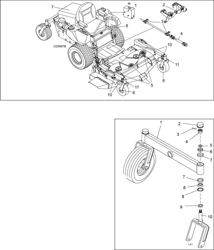
Figure 5. Lubrication Diagram
TAILWHEEL MAINTENANCE
Once a year, disassemble tailwheel assembly and inspect roller bearings:
1.Remove dust cap (2) from top of tailwheel assembly (1).
2.Remove cotter pin (3) and slotted hex nut (4).
3.Remove wheel fork (10), bearing cones (6) and remaining hardware from assembly.
4.Inspect bearing cones (6) and bearing cups (7) for wear and replace if necessary. Replace seals and washers as necessary.
5.Pack bearing cones (6) with a good grade wheel bearing grease.
6.Install wheel fork (10) bearing cones (6) and remaining hardware into assembly as shown.
7.Set bearings by torquing nut to 26 lbs-ft. All bearing free play should be removed.
NOTE: Proper bearing adjustment is essential to good bearing life.
If bearings are loose, casters will wobble and/or slap side-to-side.
If bearings are overtightened, loosen hex nut and rap shaft with a lead hammer to loosen bearings. Readjust bearings until proper setting is obtained.
1.Tailwheel assembly
2.Dust cap
3.Cotter pin
4.Slotted hex nut
5.Bushing washer 3/4 x 14 GA
6.Bearing cone
7.Bearing cup
8.Seal
9.Spacer
10.Wheel fork
Figure 6. Tailwheel Assembly (Typical)
MAN0875 (2/8/2011) |
Owner Service 17 |
|
|
 Loading...