


111876 LOADER MOUNTING KIT
Loaders 1020 1027
Includes
Valve Kit 46675
Hose Kits 57923 1001420
mounting to
Ford New Holland Tractor Models
2810, 2910, 3910 FWA 3230, 3430, 3930, 4610, 4630 2WD & FWA 4000, 4100, 4110, 4600, 4610 All-Purpose 2WD
MAN0063
MAN0063 (Rev. 1/25/02)

TO THE DEALER:
Assembly and proper installation of this product is the responsibility of the WOODS dealer. Read manual instructions and safety rules. Make sure all items on the Dealer’s Pre-Delivery and Delivery Check Lists in the Operator’s Manual are completed before releasing equipment to the owner.
TO THE OWNER:
Read this manual before operating your WOODS equipment. The information presented will prepare you to do a better and safer job. Keep this manual handy for ready reference. Require all operators to read this manual carefully and become acquainted with all the adjustment and operating procedures before attempting to operate. Replacement manuals can be obtained from your dealer or, in the United States and Canada, by calling 1-800-319-6637.
The equipment you have purchased has been carefully engineered and manufactured to provide dependable and satisfactory use. Like all mechanical products, it will require cleaning and upkeep. Lubricate the unit as specified. Observe all safety information in this manual and safety decals on the equipment.
For service, your authorized WOODS dealer has trained mechanics, genuine WOODS service parts, and the necessary tools and equipment to handle all your needs.
Use only genuine WOODS service parts. Substitute parts will void the warranty and may not meet standards required for safe and satisfactory operation. Record the model number and serial number of your equipment in the spaces provided:
Model: 111876 Loader Mounting Kit
Provide this information to your dealer to obtain correct repair parts.
Throughout this manual, the term IMPORTANT is used to indicate that failure to observe can cause damage to equipment. The terms CAUTION, WARNING and DANGER are used in conjunction with the Safety-Alert Symbol, (a triangle with an exclamation mark), to indicate the degree of hazard for items of personal safety.
This Safety-Alert Symbol indicates a hazard and means
ATTENTION! BECOME ALERT! YOUR SAFETY IS INVOLVED!
Indicates an imminently hazardous situation that, if not avoided, will result in death or serious injury.
Indicates a potentially hazardous situation that, if not avoided, could result in death or serious injury, and includes hazards that are exposed when guards are removed.
Indicates a potentially hazardous situation that, if not avoided, may result in minor or moderate injury.
Indicates that failure to observe can cause damage to equipment.
NOTE Indicates helpful information.
ii
Introduction (2/9/01)

SAFETY RULES
ATTENTION! BECOME ALERT! YOUR SAFETY IS INVOLVED!
Safety is a primary concern in the design and manufacture of our products. Unfortunately, our efforts to provide safe equipment can be wiped out by an operator’s single careless act.
In addition to the design and configuration of equipment, hazard control and accident prevention are dependent upon the awareness, concern, judgement, and proper training of personnel involved in the operation, transport, maintenance and storage of equipment.
It has been said “The best safety device is an informed, careful operator.” We ask you to be that kind of operator.
INSTALLATION
During installation, the tractor engine should be off, the key removed and the brakes locked. Do not disconnect hydraulic lines until attachments are removed or lowered to the ground and system pressure is released by operating valve levers. Never operate any hydraulic cylinders during any phase of the installation process.
This Loader Mounting Kit is to be used only for the loaders and tractors specified in the Loader Mount Installation section of this manual. Any other use or modification of this mounting kit may result in serious injury or death.
Hydraulics must be connected as instructed in this manual. Do not substitute parts, modify, or connect in any other way.
After connecting hoses, check that all control lever positions function as instructed in the Operator’s Manual. Do not put into service until control lever and equipment movements are correct.
TRAINING
Safety instructions are important! Read all attachment and power unit manuals; follow all safety rules and safety decal information. (Replacement manuals are available from dealer or, in the United States and Canada, call 1-800-319-6637.) Failure to follow instructions or safety rules can result in serious injury or death.
If you do not understand any part of this manual and need assistance, see your dealer.
Know your controls and how to stop engine and attachment quickly in an emergency.
Keep hands and body away from pressurized lines. Use paper or cardboard, not hands or other body parts to check for leaks. Wear safety goggles. Hydraulic fluid under pressure can easily penetrate skin and will cause serious injury or death.
Make sure that all operating and service personnel know that if hydraulic fluid penetrates skin, it must be surgically removed as soon as possible by a doctor familiar with this form of injury or gangrene, serious injury, or death will result. CONTACT A PHYSICIA N IMMEDIATELY IF FLU ID ENTERS SKIN OR EYES. DO NOT DELAY.
Never allow children or untrained persons to operate equipment.
PREPARATION
Check that all hardware is properly installed. Always tighten to torque chart specifications unless instructed otherwise in this manual.
Air in hydraulic systems can cause erratic operation and allows loads or equipment components to drop unexpectedly. When connecting equipment or hoses or performing any hydraulic maintenance, purge any air in hydraulic system by operating all hydraulic functions several times. Do this before p ut t i ng in t o ser vice o r allo win g an yo n e t o approach the equipment.
After connecting hoses, check that all control lever positions function as instructed in the Operator’s Manual. Do not put into service until control lever and equipment movements are correct.
Protective hose sleeves must cover all hydraulic hoses and be secured onto metal hose fittings. Replace hoses or sleeves if damaged or if protective sleeve cannot be properly positioned or secured.
Make sure all hydraulic hoses, fittings, and valves are in good condition and not leaking before starting power unit or using equipment. Check and route hoses carefully to prevent damage. Hoses must not be twisted, bent sharply, kinked, frayed, pinched, or come into contact with any moving parts. Operate moveable components through full operational range to check clearances. Replace any damaged hoses immediately.
(Safety Rules continued on next page)
Loader Mounting Kit (9/11/00)
SAFETY 1

SAFETY RULES
ATTENTION! BECOME ALERT! YOUR SAFETY IS INVOLVED!
(Safety Rules continued from previous page)
Do not connect a low-pressure hydraulic hose into a high-pressure system—it will burst the hose. Do not use a high-pressure hose in place of a lowpressure hose—it is possible to rupture the valve.
Always wear relatively tight and belted clothing to avoid entanglement in moving parts. Wear sturdy, rough-soled work shoes and protective equipment for eyes, hair, hands, hearing, and head.
Make sure attachment is properly secured, adjusted, and in good operating condition.
Power unit must be equipped with ROPS or ROPS cab and seat belt. Keep seat belt securely fastened. Falling off power unit can result in death from being run over or crushed. Keep foldable ROPS systems in “locked up” position at all times.
Whenever 3-point implements are attached to tractor, always check full range of operation for mechanical or hydraulic hose interference.
Make sure all safety decals are installed. Replace if damaged. (See Safety Decals section for location.)
Make sure shields and guards are properly installed and in good condition. Replace if damaged.
OPERATION
Do not allow bystanders in the area when operating, attaching, removing, assembling, or servicing equipment.
Keep bystanders away from equipment.
Do not operate equipment while under the influence of alcohol or drugs.
Always comply with all state and local lighting and marking requirements.
Never allow riders. Do not lift or carry anybody on the loader or in the bucket or attachments.
Power unit must be equipped with ROPS or ROPS cab and seat belt. Keep seat belt securely fastened. Falling off power unit can result in death from being run over or crushed. Keep foldable ROPS systems in “locked up” position at all times.
Always sit in power unit seat when operating controls or starting engine. Securely fasten seat belt, place transmission in neutral, engage brake, and ensure all other controls are disengaged before starting power unit engine.
Before dismounting power unit or performing any service or maintenance, follow these steps: disengage power to equipment, lower the 3-point hitch and all raised components to the ground, operate valve levers to release any hydraulic pressure, set parking brake, stop engine, remove key, and unfasten seat belt.
Never work under a raised loader. Always lower loader to the ground with bucket or loader attachment in full roll-back position. Shut off tractor, set parking brake, and remove key. Operate valve levers to release any hydraulic pressure. If loader obstructs tractor maintenance, loader must be removed from tractor.
MAINTENANCE
Before dismounting power unit or performing any service or maintenance, follow these steps: disengage power to equipment, lower the 3-point hitch and all raised components to the ground, operate valve levers to release any hydraulic pressure, set parking brake, stop engine, remove key, and unfasten seat belt.
Never work under a raised loader. Always lower loader to the ground with bucket or loader attachment in full roll-back position. Shut off tractor, set parking brake, and remove key. Operate valve levers to release any hydraulic pressure. If loader obstructs tractor maintenance, loader must be removed from tractor.
Refer to loader manual and follow all maintenance safety rules and instructions.
Do not modify or alter or permit anyone else to modify or alter the equipment or any of its components in any way.
Your dealer can supply original equipment hydraulic accessories and repair parts. Substitute parts may not meet original equipment specifications and may be dangerous.
Always wear relatively tight and belted clothing to avoid entanglement in moving parts. Wear sturdy, rough-soled work shoes and protective equipment for eyes, hair, hands, hearing, and head.
Do not allow bystanders in the area when operating, attaching, removing, assembling, or servicing equipment.
Make sure attachment is properly secured, adjusted, and in good operating condition.
2 SAFETY
Loader Mounting Kit (9/11/00)

SAFETY RULES
ATTENTION! BECOME ALERT! YOUR SAFETY IS INVOLVED!
Keep all persons away from operator control area while performing adjustments, service, or maintenance.
Tighten all bolts, nuts and screws to torque chart specifications. Check that all cotter pins are installed securely to ensure equipment is in a safe condition before putting unit into service.
Make sure all safety decals are installed. Replace if damaged. (See Safety Decals section for location.)
Make sure shields and guards are properly installed and in good condition. Replace if damaged.
Do not disconnect hydraulic lines until all system pressure is relieved. Lower unit to ground, stop engine, and operate all hydraulic control levers.
Loader Mounting Kit (9/11/00)
SAFETY 3

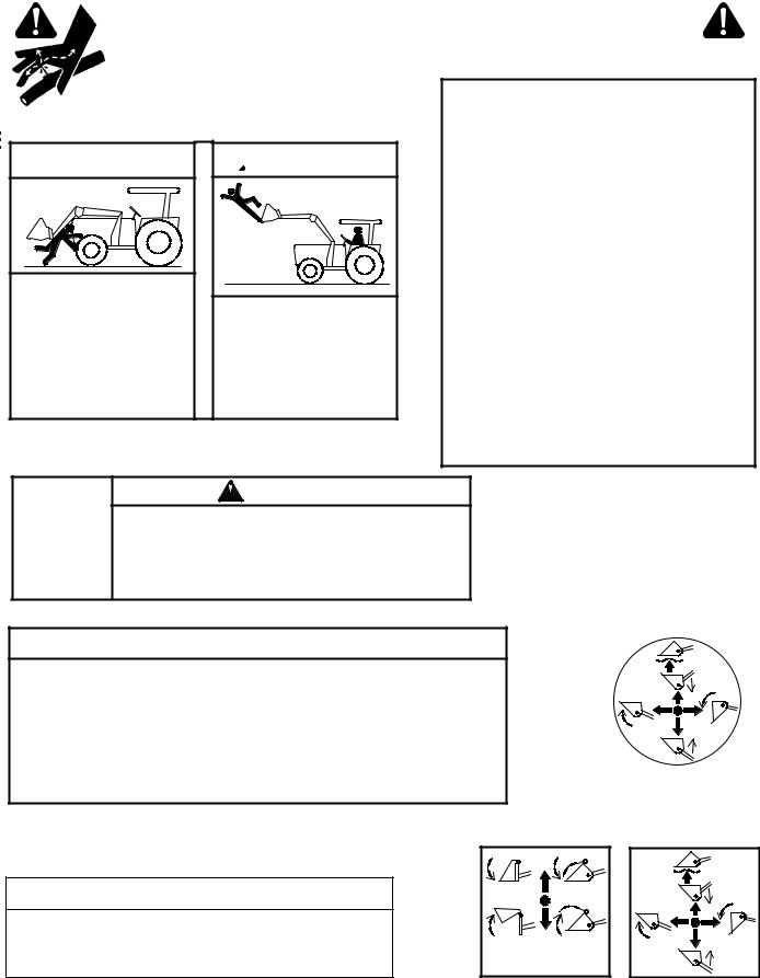
SAFETY & INSTRUCTIONAL DECALS
ATTENTION! BECOME ALERT! YOUR SAFETY IS INVOLVED!
Replace Immediately If Damaged!
MODEL NO. |
|
SERIAL NO. |
|
|
|
ID NO.
OREGON, IL U.S.A.
4 - SERIAL NUMBER PLATE
2 - PN 56053

 DANGER
Serious injury or death can result from contact with electrical lines.

 DANGER
ROLLOVERS CAN
RESULT IN INJURY
OR DEATH
Always use ROPS and seat belt.
Add rear tractor ballast.
Move wheels to widest setting.
Avoid slope operation.
Operate at low speeds.
Carry load low.
56053-A
4 SAFETY
|
6 |
MASS (KG) |
5 |
YR OF MFG.
7
11
8
Optional Loader
Control Valve
10
3 - PN 56051
 WARNING
Read and understand Operator’s Manual before operating. (Replacement manuals are available from dealer or, in the United States and Canada, call 1-800-319-6637.)
Keep others away when operating loader.
Do not allow children or untrained persons to operate equipment.
Lower loader to ground, stop engine, set park brake and remove key before leaving tractor seat.
Failure to follow safety rules can result in serious injury or death.
56051-A
1
2
3
4
9
Loader Mount
(Left Side)
1 - PN 56052
 )
)
! " #
$ %
& #'
!
" #
|
|
|
! # |
|
( # |
(Safety Decals continued on next page)
MAN0063 (12/15/00)
SAFETY & INSTRUCTIONAL DECALS
ATTENTION! BECOME ALERT! YOUR SAFETY IS INVOLVED!
Replace Immediately If Damaged!
(Safety Decals continued from previous page)
6 - PN 56050
 WARNING
CRUSHING HAZARD
To avoid injury or death:
Do not walk or work underneath a raised loader.
Lower loader to ground before leaving tractor seat.
 WARNING
FALLING HAZARD
To avoid injury or death:
Do not work from or allow riders on loader or its attachments.
5 - PN 19924
LOADER MOUNTING INSTRUCTIONS
Read Operator’s Manual instructions before proceding.
To Remove Loader
1.Park tractor on level surface with bucket flat on ground.
2.Dump bucket to take weight off mount pins and allow for stand installation. Set brake and shut off tractor.
3.Remove stands from crosstube and pin into brackets. (Pin location noted in mounting manual.)
4.Remove mount pins from loader upright.
5.Roll back bucket completely to raise uprights from mounts.
6.Shut off engine. Disconnect hydraulics. Back tractor away. Store mount pins in loader uprights.
1.Remove mount pins from uprights.
2.Drive tractor into loader slowly.
3.Shut off tractor. Connect hydraulics.
4.Dump bucket to lower upright into mounts.
5.Continue dumping bucket until uprights settle into mounts, pins can be installed and stands can be removed. Set brake and shut off tractor.
6.Install mount pins and clips. Remove stands and pin into crosstube.
WARNING
Check for leaks with cardboard; never use hand.
Before loosening fittings: lower load, release pressure, and be sure oil is cool.
Consult physician immediately if skin penetration occurs.
 WARNING
LOADER ATTACHMENT CAN FALL OFF IF NOT PROPERLY ATTACHED.
Read operator’s manuals for instructions.
Position and align loader to attachment.
Rotate coupler handles to full locked position. Lockpins must fully extend and engage into attachment retaining slots.
Attachment mechanism must be functional and in good repair.
Only use loader manufacturer approved attachments.
For information on approved attachments, call 1-800-319-6637.
Failure to follow these instructions can result in serious injury or death. 56055-B
7 - PN 56055
11 - PN 45024
 WARNING
Only use loader manufacturer approved attachments. |
|
Failure to do so can cause serious injury or death. |
45024-A |
|
10 - PN 56889
(WHEN EQUIPPED)
|
|
|
56889 |
|
|
|
|
|
|
||
|
|
|
|
|
|
|
|
|
|
|
|
8 - PN 260274
(WHEN EQUIPPED
|
|
|
260274-C |
MAN0063 (Rev. 12/15/00) |
SAFETY 5 |
|
|
|
|

NOTES
6 Mount Installation |
MAN0063 (12/15/00) |
|

LOADER MOUNT INSTALLATION
|
CAUTION |
■Only use #111876 Loader Mounting Kit for mounting Woods 1020/1027 loaders on Ford New Holland 2810, 2910, 3910 FWA & 3230, 3430, 3930, 4610, 4630 2WD & FWA, and 4000, 4100, 4110, 4600, 4610 all-purpose 2WD tractors. Any other use or modification of this mounting kit may result in serious injury or death.
■Safety instructions are important! Read all attachment and power unit manuals; follow all safety rules and safety decal information. (Replacement manuals are available from dealer or, in the United States and Canada, call 1-800-319-6637.) Failure to follow instructions or safety rules can result in serious injury or death.
■If you do not understand any part of this manual and need assistance, see your dealer.
■Always wear relatively tight and belted clothing to avoid entanglement in moving parts. Wear sturdy, rough-soled work shoes and protective equipment for eyes, hair, hands, hearing, and head.
IMPORTANT
■ This equipment must be assembled and installed on the customer’s tractor by the Woods dealer. Dealer must thoroughly inspect equipment and complete each item on the PRE-DELIVERY CHECK LIST, DELIVERY CHECK LIST, and WARRANTY REGISTRATION before equipment is released to the customer.
TRACTOR PREPARATION
For installing this mounting kit, references to right, left, forward, and rearward directions are determined from the operator’s position in the tractor seat.
1.Shut off engine and set parking brake during installation.
2.Remove the tractor front weights and weight bracket if equipped.
3.Set tractor front wheel width to 61-1/2” (center line of thread) as instructed in tractor operator manual.
4.Remove cowl-mounted headlights if equipped.
MAN0063 (12/15/00) |
Mount Installation 7 |
|
|
LOADER MOUNT INSTALLATION Cont’d
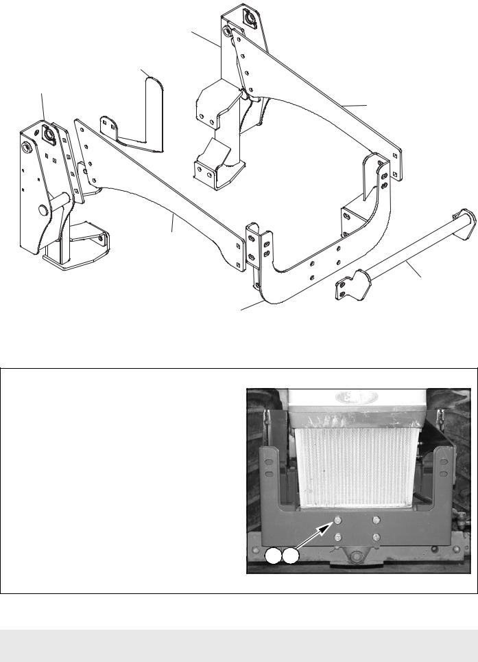
#1001629 |
Left Rear Mount |
#1001408 |
Hose Holder |
#1001628 |
Right Rear Mount |
#1001634 |
Side Rail |
#1001634 |
Side Rail |
CD5819A var |
#57864 |
Complet Grill |
Guard Kit |
#1002769 |
Front Mount |
Figure 1 #111876 Loader Mounting Kit
Install Front Support
NOTE: Leave cap screws loose until front support and loader mounts are completely installed.
1. Attach front support to tractor, using cap screws
(11) and hardened flat washers (13) as shown in Figure 2.
11. 300517 3/4 NC x 1-3/4 Cap screw
13.57798 3/4 Flat washer
11 
 13
13 
Figure 2 Front Support Installation
8 Mount Installation
(Rev. 1/25/02)
MAN0063 (12/15/00)
LOADER MOUNT INSTALLATION Cont’d
Install Grill Guard (Optional)
1. Attach grill guard to front support, using four 3/4 NC x 2 hex head cap screws (15), flat washers (13), lock washers (23), and nuts (22).
NOTE: Install cap screws from inside front support as shown in Figure 3.
13.57798 3/4 Flat washer
15.735 3/4 x 2 Cap screw
22. 1450 3/4 Nut
23.2522 3/4 Lock washer
15  13
13  23
23  22
22 
Figure 3 #57864 Grill Guard Kit Installed
Install Right & Left Mounts to
Clutch Housing
1. Attach right and left mounts to tractor clutch |
11 |
13 |
|
housing, using cap screws (11, 15) and flat washers |
|||
|
|
(13)as shown in Figure 4.
11.300517 3/4 x 1-3/4 Cap screw
13.57798 3/4 Flat washer
15.735 3/4 x 2 Cap screw
15  13
13 
Figure 4 Right Mount Installed at Clutch Housing
MAN0063 (12/15/00) |
Mount Installation 9 |
|
|
 Loading...