

Wolf MUS 85, MKS 140, MUS 100, MKS 250, MKS 190 Technical Manual And Installation Instructions
...
1
Technical Guide
and
Installation Instructions
MKS / MUS Steel boiler
70 - 550 kW
The installation instructions for the Unit pressure jet oil burner is included in the pressure
jet oil burner pack.
The control unit installation and service instructions
included in the control unit pack.
Wolf GmbH · 84048 Mainburg · Postfach 1380 · Telephone +49-8751/74-0 · Fax +49-8751/741600
Part no. 30 48 034 03/03 TV GB
2
Suitable for heating systems in accordance with DIN 4751 part 1 and 2 with maximum
flow temperatures up to 120 °C.
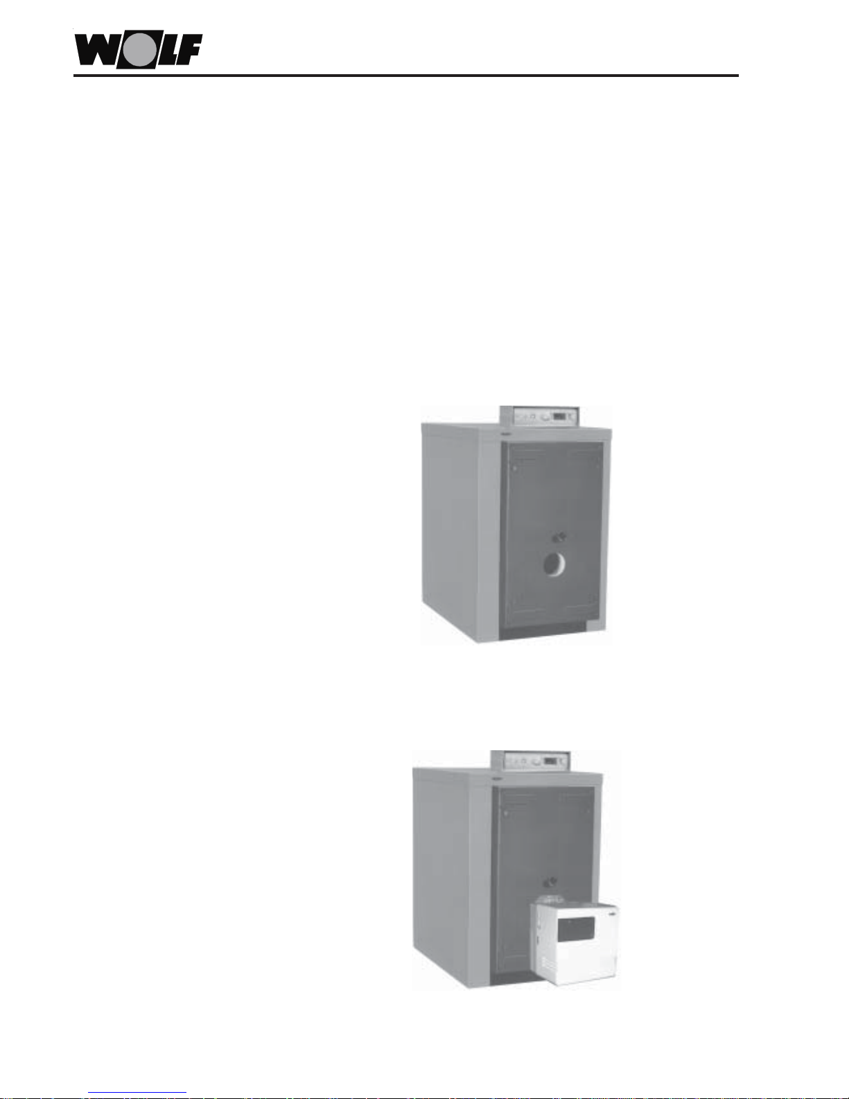
Oil- and gas-fired steel boilers
Type MKS
Oil-fired Unit steel boilers
with two-stage pressure jet oil burner
Type MUS
Oil- and gas-fired steel boiler for pressure jet combustion in accordance with EN 303
and EC Directive 90/396/EEC (gas consuming equipment), 73/23/EEC (Low Voltage
Directive), 89/336/EEC (EMC Directive), 92/42/EEC (Hot Water Boiler Efficiency) and 93/
68/EEC (Identification Directive) for heating systems with heating circuit pumps and
flow temperatures up to 110 °C and 4 bar permissible operating pressure in accordance
with DIN 4751 and max. DHW cylinder pressure 10 bar in accordance with DIN 4753.
The NOx limits required by the 1st BImSchV §7(2) are maintained.
3
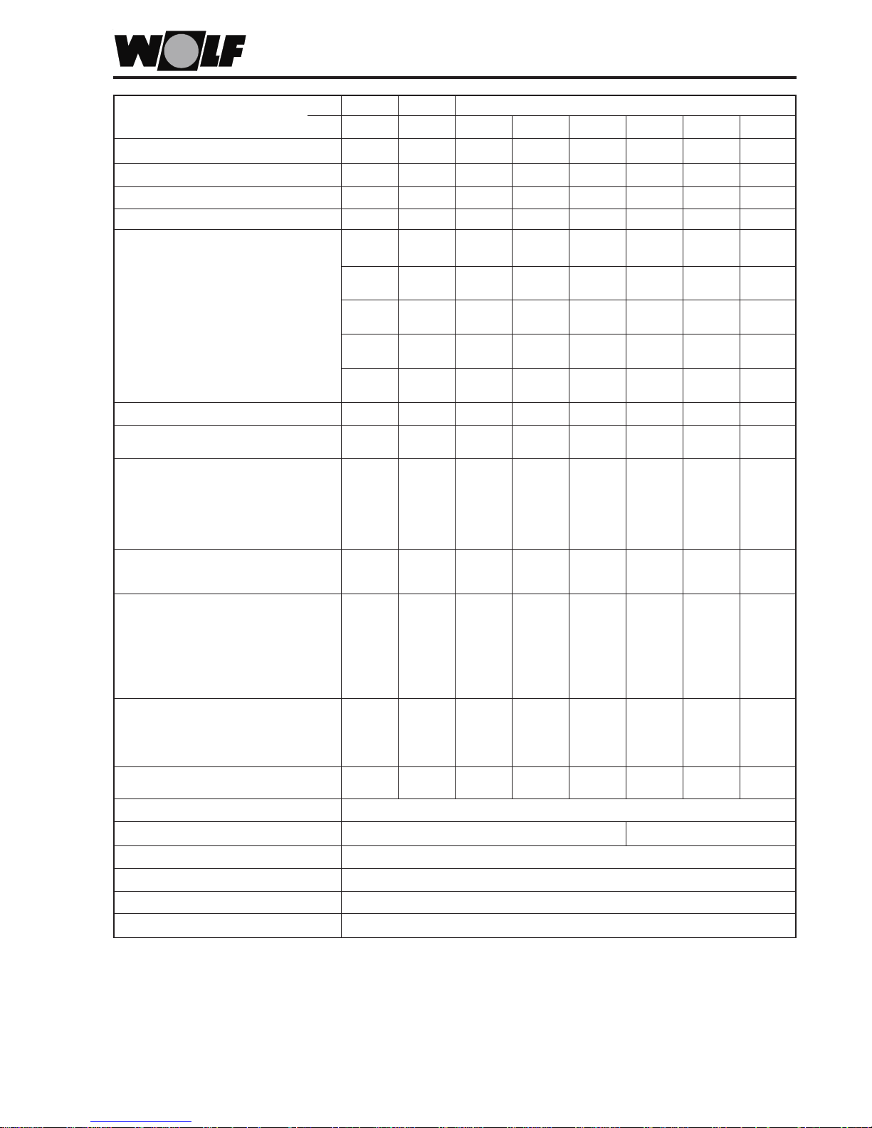
Specification
Boiler type MUS 85 100
MKS 85 100 140 190 250 340 420 500
Output range oil/gas (MKS) kW 70-100 85-120 110-160 160-230 200-300 280-380 360-460 420-550
Recommended range (MKS) kW 70-85 85-100 110-140 160-190 200-250 280-340 360-420 420-500
Upper range oil (MUS) kW 70-85 85-100 - - - - - Set output UNIT burner MUS kW 85 100 - - - - - Flue gas temperatures
1)
from/to °C 145-165 145-165 145-165 145-165 145-165 150 -170 150-165 155-1 70
1st stage flue gas temperature °C 120 120 1 20 120 120 120 120 120
Flue gas mass flow rate
1)
Fuel oil EL CO2=13% kg/h 127-142 142 -168 184-235 269-319 336-420 470-571 605-706 706-840
Flue gas mass flow rate
1)
Natural gas E CO2=9.5% kg/h 125-151 151-178 196-249 285-338 356-445 498-605 641-748 748-890
Flue gas mass flow rate
1)
Natural gas LL CO2=9.0% kg/h 129-157 157-185 203-259 296-351 370-462 517-628 665-776 776-924
Flue gas mass flow rate
1)
LPG CO2=11% kg/h 120-146 146-172 189-240 274-326 343-429 480-583 618-721 721-858
Relative standby loss q
B
% 0.7 0.7 0.6 0.5 0.5 0.4 0.4 0.3
Total weight MKS kg 406 413 524 730 772 908 975 1035
Total weight MUS kg 426 433 - - - - - -
Boiler dim. Width m m 796 796 796 976 976 1036 1036 1036
Height
2)
mm 1335 1335 1335 1500 1500 1680 1680 1680
Length MKS mm 1415 1415 1760 1950 1950 2085 2085 2085
Length MUS mm 1825 1825 - - - - - -
Flue pipe Ø mm 178 178 195 195 195 250 250 300
Burner aperture MKS mm 130 130 130 245
3)
245
3)
305
3)
305
3)
305
3)
Minimum blast tube length MKS mm 170 170 170 215 215 125 125 125
Foundation / plinth Height mm 80/80 80/80 80/80 80/80 80/80 80/- 80/- 80/-
Width mm 800/850 800/850 800/850 1000/950 1000/950 1100/- 1100/- 1100/Length mm 1360/1300 1360/1300 1700/1500 1850/1500 1850/1500 2000/- 2000/- 2000/-
Boiler flow
(flange) DN 65 65 65 80 80 100 100 100
Safety flow, air-vent valve
(male thread) R 1¼" 1¼" 1¼" 1 ½ " 1½ " 2" 2" 2 "
Boiler return
(flange) DN 65 65 65 80 80 100 100 100
Filling, draining, safety return
(male thread) R 1 ½ " 1 ½ " 1 ½" 1 ½ " 1 ½ " 1½ " 1 ½ " 1 ½"
Boiler water content l 216 213 288 508 494 697 665 635
Boiler gas content l 14 0 143 206 333 3 46 428 445 460
Heating surface m23.5 3.8 5.2 8 8.4 10.6 12.5 14.2
Flue gas resistance
1)
mbar 0.3 0.4 0.8 1.1 1.4 2.0 2.0 2.0
Heating water resistance (at Dt=20K)1)mbar 1.2 1.7 3.5 4.5 5.5 9.0 14.0 19.0
Combustion cham. dia. Length mm 808 808 1158 1292 1292 1496 1496 1496
Diameter mm 447 447 447 547 547 588 588 588
Type approval ID 02-226-626
ÖVGW-Reg.-Nr. G2,416
CE designation CE-0085AR0034
Electrical connection 230V / 50Hz / 10A
Max. perm. temperature
4)
°C 120
Max. boiler pressure bar 4
1)
At a mean boiler water temperature of 60 °C for the upper and lower output of the recommended range.
2)
Including control unit
3)
Plain burner plate, drill on-site.
4)
Adjustable high limit safety cut-out: 120/110/100 °C at R31 STAV, R32, R33 and R33/4 (not applicable to installations in Austria).
The chimney stack dimensions must be calculated in accordance with DIN 4705, or local regulations. For flue gas temperatures below 160 °C,
combustion equipment must be connected to highly insulated chimney stacks (heat conductivity resistance class I acc. to DIN 18160 T1) or use
suitable, moisture-resistant, type-tested, flue gas systems.
4
These installation instructions apply exclusively to WOLF oil- and gas-fired boilers as
well as to WOLF Unit steel boilers.
Authorised personnel should read these instructions before any installation,
commissioning or maintenance work. Adhere to the instructions given in this document.
Non-adherence to these installation instructions voids WOLF warranty.
The following symbols and references are used in these installation instructions:
Non-observance of these references can put individuals at risk.
Non-observance of these references can lead to damage to the oil/gas-fired boiler or
the Unit boiler.
In addition to the installation instructions, operating instructions and adhesive labels
are included or fitted to the boiler. These must also be observed.
Observe the enclosed references for heating system installers.
Only qualified and trained personnel may install, commission and maintain these
boilers.
In accordance with VDE 0105 part 1, work on electrical components (e.g. control unit)
may only be carried out by qualified electricians.
The regulations of VDE/ÖVE and those of your local electricity supplier as well as all
other local regulations are apply to electrical installation work.
Only operate the boiler within its output range which is stated in the specification
supplied by WOLF.
Appropriate use of the boiler refers to the exclusive use in hot water heating systems
in accordance with DIN 4751.
Never remove, bypass or otherwise disable any safety and monitoring equipment.
Only operate the boiler in perfect technical condition.
Any faults and damage with a potential impact on safety, which might limit the safe use
of the equipment, must be remedied immediately by a qualified contractor.
Replace faulty components or equipment only with original WOLF spare parts.
The boilers described in these installation instructions are low-temperature boilers
according to HeizAnlV and 92/42/EEC (Hot Water Boiler Efficiency).
In accordance with the Heating System Order, heating systems above 70 kW may not
be operated in single stage mode.
Retain the enclosed operating instructions clearly visible in the boiler room. Insert all
further documentation in a clear wallet and clip to the boiler side casing.
Your boiler and burner should be maintained and cleaned on an annual basis by a
heating contractor, to ensure the reliable and economic function of your heating system.
We would recommend a maintenance contract.
Boilers may only be installed and operated in boiler rooms which are suitable according
to the Landes-FeuVo [or local regulations].
General
Reference symbols
Safety instructions
Standards and regulations
Safety instructions
Please note:
5
Installation references
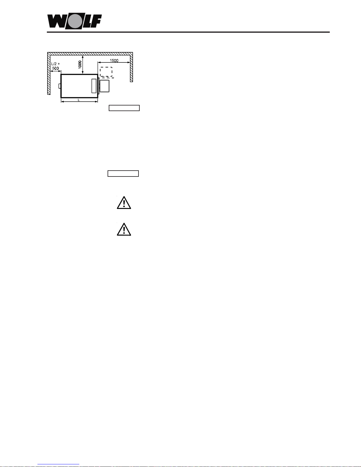
Positioning
The boiler should be installed on a level surface which is substantial enough to carry
its weight.
It is recommended to place the boiler on a foundation or plinth. For dimensions see
the specification.
During the boiler installation observe all building regulations, the FeuVo and VDI 2050
[in Germany] and local regulations, particularly regarding the size of the boiler room,
the fresh air and exhaust air ventilation as well as the chimney stack connection.
Only install the boiler in boiler rooms which are free from frost and where adequate
ventilation is ensured.
Drain the boiler, the DHW cylinder and the entire heating system if there is a danger of
frost, if the system has been shut down.
Position the boiler horizontally or slightly rising towards the back to ensure adequate
venting of any trapped air.
Boilers should not be installed in areas subject to aggressive vapours or very dusty/
highly humid conditions (workshops, washrooms, hobby rooms etc).
The combustion air must be free from halogenated hydrocarbons (e.g. as contained
in sprays, solvents and cleaning fluids, paints and adhesives) and high dust
concentration.
Clearances towards walls and combustible materials must comply with local fire
regulations. The above clearances are recommended.
Keep the flue pipe connection as short as possible and inclined towards the chimney
stack.
Thoroughly seal-in the flue pipe.
Use flue pipe bends with clean-out covers to facilitate the cleaning of the flue pipe.
Repositioning the fixing screws enables the boiler door to be opened in the opposite
hand.
Please note:
Please note:
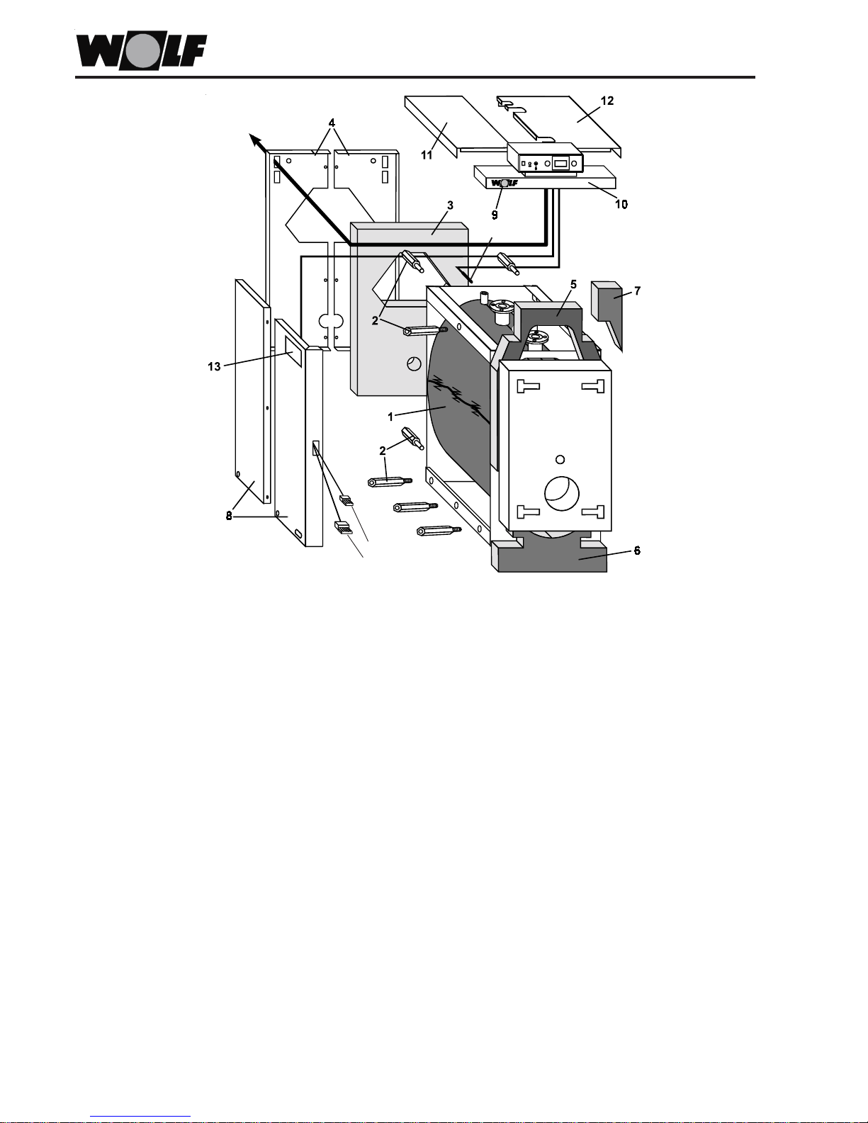
6
1 Thermal insulation: Position (overlapping) around the boiler block and secure with spring clips.
2 Spacers: Secure on the boiler with nuts enclosed.
(MKS-85 to 500) Four spacers at the real panel.
(MKS-85 to 140) Two bottom spacers per side.
(MKS-190 to 500) Three bottom spacers per side and one central top spacer.
3 Thermal insulation: Loosely fitted to the rear boiler wall.
4 Rear panels: Centrally locate both parts and secure with self-tapping screws and with the screws (M8x16)
supplied on the rear boiler wall spacers.
5 Thermal insulation: Insert from the top between door and boiler front and locate on the boiler front.
6 Thermal insulation: Fit loosely to the boiler front and secure with spring clips.
7 Thermal insulation: Fit loosely to the boiler front and secure with adhesive strips.
8 Side panels: Push the l.h./r.h. casing over the rear panel and secure with the screws
(MUS-85 to 100 / MKS-85 to 140) (M8x16) supplied to the lower two spacers.
8 Side panels: Secure the l.h./r.h. front and rear panels with screws (M6x10) then push over the rear panel
(MKS-190 to 500) and secure with the screws (M8x16) supplied on the lower three spacers.
9 Wolf label: Hook into the front panel lid (10).
10 Front panel lid: Locate and click into the panel with fitted control unit.
Only complete the fitting of the casing after the control unit has been installed (page 7).
10 Panel lid l.h. rear: Locate on the panel and click into place.
10 Panel lid r.h. rear: Locate on the panel and click into place.
13 Type plate: Affix to the boiler in a clearly visible position.
Accompanying documentation: Affix with the clips supplied to the side of the boiler.
Casing installation
Burner cables
1st stage
2nd stage
Boiler sensor
Control unit cable
 Loading...