

Wolf LX-400EL, LX-400EH Operation And Maintenance Instructions
Wolf LinkExTM LED Temporary Emergency Luminaire
Operation and Maintenance Instructions
Please Retain - Read Before Use
EU Declaration of Conformity
The Wolf ATEX LX-400E LinkEx LED Temporary Emergency Luminaire meets all
relevant provisions of the 2014/34/EU Explosive Atmospheres (ATEX Equipment)
Directive by virtue of the issued EU type examination certicate, conrming
compliance with all relevant harmonised standards and essential health and
safety requirements.
The Wolf ATEX LinkEx LED Temporary Emergency Luminaire is a leadlamp with
an emergency illumination function powered by a NiMH rechargeable battery
and is normally powered by a cabled 18-55AC or 90-264AC power source. It
is constructed with a durable enclosure construction of polycarbonate with
polyurethane protective rings. Approval is as Group II, Category 2 equipment for
use in zone 1 & 2 potentially explosive gases, vapours, mists and dusts where
the T4 temperature class/135ºC maximum surface temperature permits.
Certication/Approval Code:
II 2GD
Ex eb mb op is IIC T4 Gb
Ex tb op is IIIC T135°C Db IP6X
Ta = -20°C to +55°C
or Ta = -20°C to +45°C when the LX-621 optional Protection Cover is tted
EU Type examination certicate: Sira 12ATEX3177X
Notied Body: SGS FIMKO OY, PO Box 30 (Särkiniementie 3),
00211, Helsinki, Finland
EU Notied body number: 0598
Harmonised standards applied:
EN60079-0:2012 + A11:2013, EN60079-7:2015, EN60079-18:2015,
EN60079-28:2015, EN60079-31:2014
Ingress protection level IP67 to EN60529:1992
Some variants of plugs/sockets may reduce the Ingress Protection rating.
e.g. ATX & CEAG IP66.
ATEX LinkEx LED Leadlamps are certied compliant with the 2014/30/EU EMC
Directive to the harmonised standards: - EN 55015: 2013 +A1:2015,
EN 61547: 2009, EN 61000-3-2:2014, EN 61000-3-3:2013
Alex Jackson – Managing Director
Wolf Safety Lamp Company Ltd.
IECEx Scheme Certification
Certicate number: IECEx SIR 12.0070X
Certication/Approval Code: Ex eb mb op is IIC T4 Gb
Ex tb op is IIIC T135°C Db IP 6X
Ta = -20°C to +55°C
or Ta = -20°C to +45°C when the LX-621 optional Protection Cover is tted
Standards applied: IEC60079-0:2011, IEC60079-7:2015, IEC60079-18:2014,
IEC60079-28:2015, IEC60079-31:2013
IMPORTANT: SPECIAL CONDITIONS OF USE (X)
1. The user/installer shall ensure that, when the Luminaire is tted with a
previously certied plug or socket that has associated special conditions for
safe use, they shall take into account any restrictions or conditions for safe use
that are applicable to these devices.
2. Linkable lamps tted with Marechal sockets are certied for low impact risk
use only, do not expose to shocks greater than 4 joules.
3. The LED Temporary Emergency Luminaire can be tted with a protective
cover (LX-621), when tted the maximum ambient temperature lowers from
+55°C to +45°C. Use only Wolf supplied accessories.
PHOTOBIOLOGICAL SAFETY
Floodlites are risk group 1 - No photobiological hazard under normal
behavioural conditions.
EQUIPMENT USE
1. This product incorporates an emergency function which allows the lamp to
illuminate at a reduced level in the event of supply failure. The batteries will
charge when the lamp is powered.
2. Check the rating label to ensure the LinkEx LED leadlamp is suitable for
the supply provided, ambient temperature present and the environmental
conditions.
3. In areas where processes that induce circulating currents in the earth
system are being undertaken, such as welding, it is the user’s responsibility to
ensure there is no potential difference between the supply earth and the earth
local to the luminaire. If a potential difference exists there is a risk of arcing
should the lamp’s end cap xings or metal gland come into contact with local
metal work. In these situations, the luminaire should also be locally earth
bonded with a exible cable, no longer than 2 metres, with a conductor area of
6mm2 minimum. The luminaire must be de-energised from the mains supply
during connection or disconnection of the local earth bond. An external Earth
Bonding Stud is available in the spares list and can be retro tted in place of
one of the end cap retaining screws.
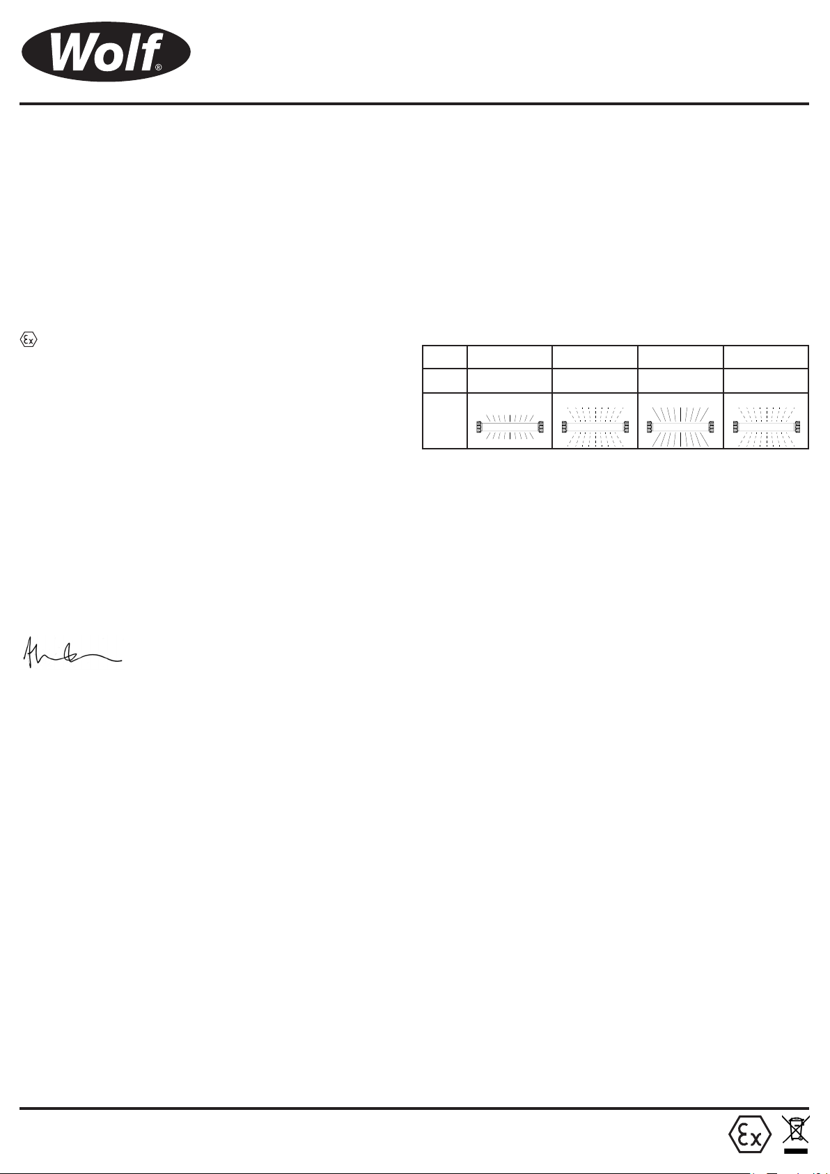
4. Safe Optimal Voltage Indicator (SOVI). The Wolf LX-400E LED Leadlamp
incorporates SOVI technology to highlight to the user if the product is operating
outside of the certied maximum and recommended minimum voltage range.
The diagram below represents the SOVI function, it demonstrates that when
the voltage is not within the “Safe/Optimal Voltage” the light output will change
from a constant uninterrupted beam to a pulse.
SOVI EMERGENCY MODE SAFE NON-OPTIMAL
LX-400EL
LX-400EH
LIGHT
OUTPUT
< 18V
< 90V
REDUCED LIGHT
OUTPUT
VOLTAGE
18-20V
90-95V
PULSE ON PULSE
SAFE OPTIMAL
VOLTAGE
20-55V
95-264V
UNSAFE
VOLTAGE
55V >
264V >
If connecting a large number of lamps check for SOVI indication on all the
lamps in the string. Guidance on lamp connection and extensions can be found
on the Wolf website: www.wolfsafety.com. If a lamp is indicating an unsafe
voltage, it is recommended that the lamp be switched off until it can be made
to operate at a correct voltage.
5. The LinkEx LED leadlamp enclosure is constructed from polycarbonate, the
end user must ensure suitability of the atmosphere the LinkEx LED leadlamp
will be used in.
6. The LinkEx LED leadlamp is class 1 earthed electrical equipment, using 3
core cable. This product must be earthed.
7. Ex e terminal blocks must have all terminals fully tightened down even if a
conductor is not tted. On the six way terminal block, tighten screws to 0.7Nm,
on the 4 way terminal block tighten to 1.8Nm.
8. ATEX/IECEx certied cable glands must be used and be suitable for the type
of cable used.
9. Ensure cable is rated for the ambient temperature the LinkEx LED leadlamps
will be used in, standard SY cable is not rated for use below 0ºC.
10. Inspect cable at regular intervals.
11. Damaged equipment should be withdrawn and repaired as necessary
before being put back in to service, in accordance with EN60079-17.
12. Lamps must not be opened in Hazardous Areas.
13. When the LinkEx LED leadlamp is used in temporary installations
two mounting points must be used, see Wolf clamp rings and associated
accessories.
14. LinkEx LED leadlamps can be carried whilst energised/illuminated.
15. When the Luminaire is tted with a previously certied plug or socket, the
covers must be closed to maintain their IP rating.
MAINTENANCE
1. IMPORTANT. Any maintenance work should be carried out in the safe area
only.
2. IMPORTANT. No modications are permitted to the LinkEx LED
leadlamps, use only genuine Wolf spare parts and accessories, unauthorised
modications, spare parts or accessories will invalidate certication.
3. Isolate the LinkEx LED leadlamps from the power supply before carrying out
any maintenance work. Please note that the battery pack will remain live after
the leadlamp is isolated from the power supply, even when in deep discharge
mode.
4. In case of fault indication, remove and restore external power. If fault
indication persists, contact Wolf noting the LED indications both whist external
power is applied and whilst disconnected. Any faults should be repaired prior
to storage.
5. To replace LED strip, replace entire tray (see spares list).
6. External plastic components have an anti-static coating. Use only a dilute
water/detergent mix to clean.
7. Insulation testing must be carried out to IEC, EN standards to the correct
rating i.e. 250V DC for 18-55V and 500V DC for 90-264V versions. Live and
neutral cables must be shorted together and the voltage applied between earth
and this connection.
WOLF SAFETY LAMP COMPANY
Saxon Road Works, Shefeld, S8 0YA, England
Page 1 of 4
Wolf LinkExTM LED Temporary Emergency Luminaire
BATTERY CHARGE INDICATION
The battery status is indicated by two LED indicators that are situated on the
top of the driver. These LEDs are visible through the outer tube. See below for
charge indication breakdown.
Amber LED Green LED
Status Green LED Amber LED LED Array
Driver Initialisation ON ON 10%
Maintenance Charge / Battery Full ON OFF 100%
Supply On
Supply Off
If this emergency luminaire is relied upon for the safe evacuation of personnel,
it is the user’s responsibility to ensure that the performance of the emergency
mode is suitable for their needs. It is recommended that the duration of the
discharge is tested regularly and upon powering up, the luminaire indicates
“Battery Charging”. The full capacity of the battery is not available until the
unit indicates “Maintenance Charge / Battery Full”. Contact Wolf for further
information.
Battery Charging FLASH OFF N/A
Non-Optimal / Unsafe Voltage N/A OFF Pulsing - 50%
Replace Battery FLASH FLASH 100%
Battery Fault OFF ON 10%
Battery Fault OFF ON 10%
Em. Mode - Discharging OFF OFF 50%
Em. Mode - Discharging Low Battery OFF FLASH 25%
Deep Discharge Protection OFF OFF OFF
Battery Duration: 3 hrs from fully charged
Battery Charge Time: 16 hrs
Deep Discharge Protection - The lamp will automatically cut off when the
battery reaches a pre-determined low voltage. The battery will need to be recharged before the emergency mode is functional again.
Battery Storage - To maximise the performance of the emergency function it
is recommended that the battery is charged (for 16 hours) once a month. It is
imperative that the unit is charged every three months, otherwise permanent
loss of capacity might occur. In this case, the unit will not function as an
emergency luminaire and will indicate “Replace Battery”.
Recommended battery storage temp.: +5 to +25°C
ELECTRICAL DATA
Maximum current on a linked lamp conguration not to exceed 16A.
MODEL Safe Optimal Voltage Range Freq Hz Power Watt VA
LX-400EL../T4 20-55VAC 50-60 24.5 26
20-55VDC 25
LX-400EH../T4/..110V 95-264VAC 50-60 24 25
95-264VDC 25
LX-400EH../T4/..230V 95-264VAC 50-60 25 30
95-264VDC 25
DISPOSAL OF WASTE MATERIAL
Disposal of packaging, LinkEx LED products, old LED trays and drivers should
be carried out in accordance with national regulations. (WEEE)
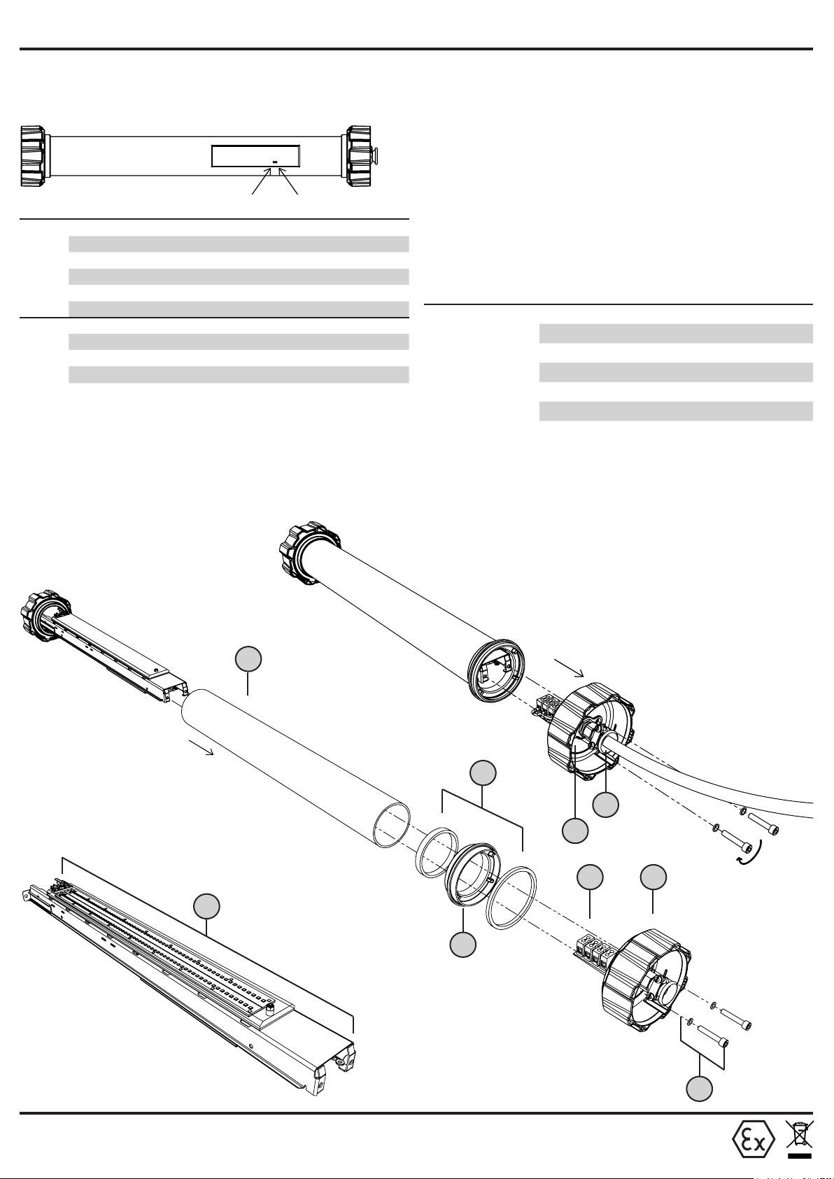
Product Breakdown
Only suitably qualied and experienced
technicians are to assemble/disassemble the
luminaire.
REPLACING TUBE
After removing the cable entry end cap, slide
the tube over the tray assembly. Ensure the
replacement tube is free from dust before
tting. If necessary, clean only the inside of
the tube with an alcohol wipe.
19
CHANGING CABLE
1. Remove the two securing screws from the cable
entry end cap, to allow access to the terminals.
2. Remove cable from terminals.
3. Unscrew the gland cable grip, to allow the cable
to be removed from gland.
For wiring details and terminal torque settings, see
wiring diagram (page 4).
3
4
20
5
6
1
Torque Setting: 3.7Nm
REPLACING THE LED ARRAY
If the LED strip is faulty, the complete tray
assembly must be replaced. See spare parts list.
WOLF SAFETY LAMP COMPANY
Saxon Road Works, Shefeld, S8 0YA, England
2
22
Page 2 of 4
 Loading...