


WARMING DRAWER
INSTALLATION INSTRUCTIONS
CAJÓN CALENTADOR INSTRUCCIONES DE INSTALACIÓN
TIROIR CHAUFFANT INSTRUCTIONS D’INSTALLATION
CASSETTO SCALDAVIVANDE ISTRUZIONI PER L’INSTALLAZIONE
INSTALLATIONSANWEISUNGEN

ENGLISH |
4 |
ESPÃNOL |
22 |
FRANÇAIS |
40 |
ITALIANO |
58 |
DEUTSCH |
76 |
3
CONTACT
INFORMATION
Website:
wolfappliance.com
WOLF® is a registered trademark of Wolf Appliance, Inc.
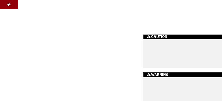
As you follow these instructions, you will notice WARNING and CAUTION symbols. This blocked information is important for the safe and efficient installation of Wolf equipment. There are two types of potential hazards that may occur during installation.
signals a situation where minor injury or product damage may occur if you do not follow instructions.
states a hazard that may cause serious injury or death if precautions are not followed.
Another footnote we would like to identify is IMPORTANT NOTE: This highlights information that is especially relevant to a problemfree installation.
WOLF WA R M I N G D R AW E R
I N S TA L L AT I O N REQUIREMENTS
IMPORTANT NOTE: This installation must be completed by a qualified technician.
Installer: Please read the entire Installation Instructions prior to installation. Save these instructions for the local inspector’s reference, then leave them with the homeowner.
Homeowner: Please read and keep these instructions for future reference and be sure to read the entire Use & Care Information prior to use.
Any questions or problems about the installation should be directed to your Wolf dealer. You can also visit our website
at wolfappliance.com.
IMPORTANT NOTE: This appliance must be installed in accordance with local codes. The correct voltage, frequency and amperage must be supplied to the appliance from a dedicated, grounded circuit which is protected by a properly sized circuit breaker or time delay fuse. The proper voltage, frequency, and amperage ratings are listed on the product rating plate.
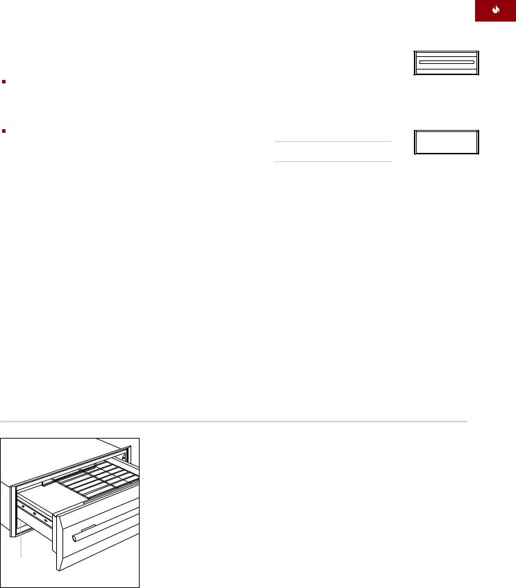
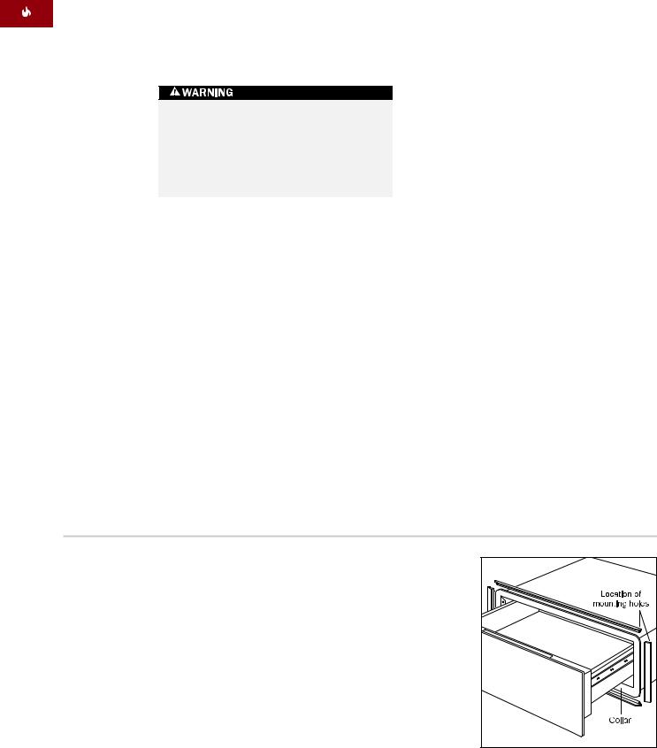
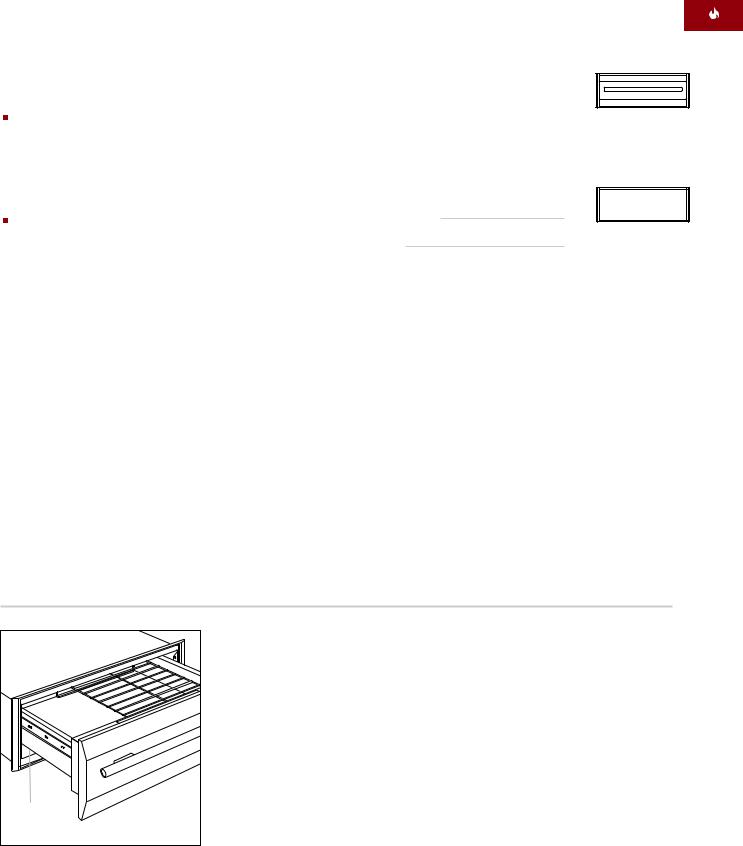
Record the model and serial numbers before installing the warming drawer. Both numbers are listed on the product rating plate, located on the left front floor area of the inner cabinet. To access the rating plate, the drawer must be fully open. Refer to the illustration below.
Model Number ICBWWD30
Serial Number
Model ICBWWD30 with Stainless Steel Drawer Front
Model ICBWWD30
with Integrated
Drawer Front
Location of |
rating plate |
Rating plate location
5

ACCESSORIES
Optional accessories are available through your Wolf dealer.
WOLF WA R M I N G D R AW E R
B E F O R E YOU START
Before you install the warming drawer, make sure you have the Wolf accessory drawer front called for in your installation.
IMPORTANT NOTE: If you are installing the warming drawer with integrated drawer front in an inset panel application, make sure that your cabinetry meets the minimum 838 mm width and 635 mm depth requirement for this installation.
Check with local utilities for electrical codes that apply in your area. Local codes vary. Installation, electrical connections and grounding must comply with applicable codes.
This appliance must be properly grounded. Refer to Electrical Requirements on
page 14.
Make sure you have the tools and materials necessary for proper installation.
D R AW E R F R ON T OPTIONS
IMPORTANT NOTE: Model ICBWWD30 must be installed with a Wolf stainless steel or integrated drawer front.
|
Classic Stainless Steel |
WWDFRONT/S |
|
||
|
Integrated Drawer Front |
WWDFRONT/I |
|
||
|
(accepts wood panel) |
|
Drawer fronts are ordered and shipped as sales accessories and include additional installation instructions. Stainless steel drawer fronts include a matching tubular handle.
The integrated drawer front accepts a custom wood panel and handle to be provided by the homeowner. Optional stainless steel tubular handles in classic stainless steel are available as sales accessories.
TO O LS AND M AT E R I A LS REQUIRED
Wood screws or other hardware to install the solid platform or runners that support the warming drawer
51 mm x 51 mm or 51 mm x 102 mm lumber for runners—runners must be able to support 91 kg
51 mm x 51 mm or 51 mm x 102 mm lumber for anti-tip block
Power saw
Level
Drill and 1,6 mm bit, 13 mm bit also for integrated drawer front application
Phillips screwdriver
2 wood screws (provided)
Wood cleats for integrated drawer front application
6
I N S TA L L AT I O N INSTRUCTIONS
S TA I N L E S S S T E E L DRAWER FRONT
INSTALLATION SPECIFICATIONS
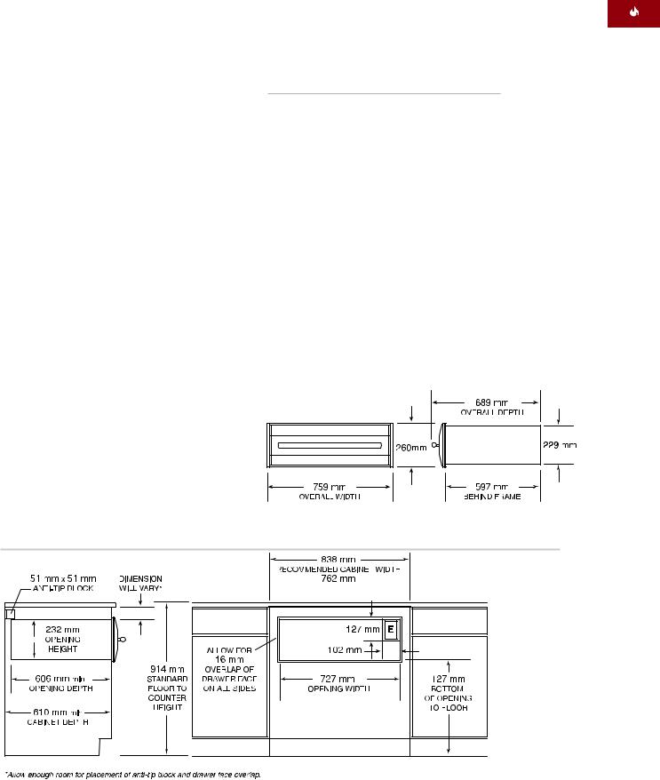
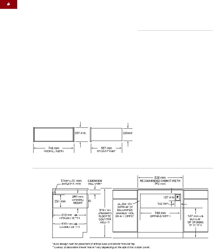
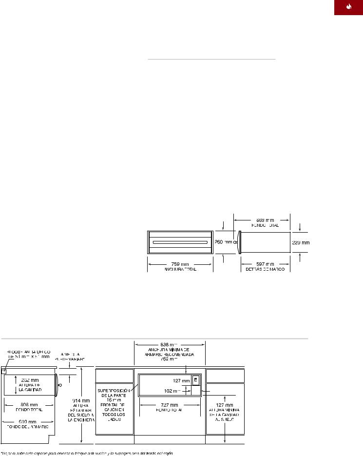
The following illustrations provide the overall dimensions and installation specifications for the Wolf warming drawer with a stainless steel drawer front.
Wolf recommends using a 838 mm wide cabinet for the warming drawer with stainless steel drawer front. A minimum 762 mm wide by 610 mm deep cabinet is required with a minimum base support of 91 kg.
Refer to pages 16–17 for stainless steel drawer front installation instructions. These instructions are also included with the stainless steel drawer front kit.
UNDERCOUNTER INSTALLATION
For undercounter installations, 597 mm from the bottom of the warming drawer opening to the floor is recommended. It must be installed a minimum of 127 mm above the floor or
25 mm above the toe kick.
The Wolf warming drawer with stainless steel drawer front may be installed below an electric or gas cooktop, provided the warming drawer is fully enclosed, top and bottom. Allow enough room for gas and electrical connections for the cooktop. Refer to installation instructions for the cooktop for additional specifications. Dimensions will vary according to the specific installation.
MODEL ICBWWD30
with Stainless Steel Drawer Front
Overall Width |
759 mm |
Overall Height |
260 mm |
|
|
Overall Depth |
689 mm |
|
|
Depth Behind Frame* |
597 mm |
|
|
Minimum Cabinet Width |
762 mm |
|
|
Minimum Cabinet Depth |
610 mm |
|
|
Minimum Base Support |
91 kg |
|
|
Opening Width |
727 mm |
|
|
Opening Height |
232 mm |
|
|
Opening Depth |
606 mm |
|
|
*Allow 10 mm additional depth for cord thickness.
Overall Dimensions – Stainless Steel Drawer Front
Undercounter Installation – Stainless Steel Drawer Front
7
WOLF WA R M I N G D R AW E R
S TA I N L E S S S T E E L DRAWER FRONT
INSTALLATION WITH BUILT-IN OVEN
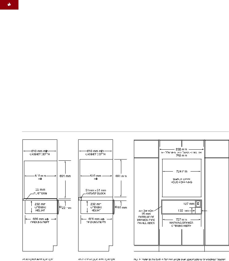
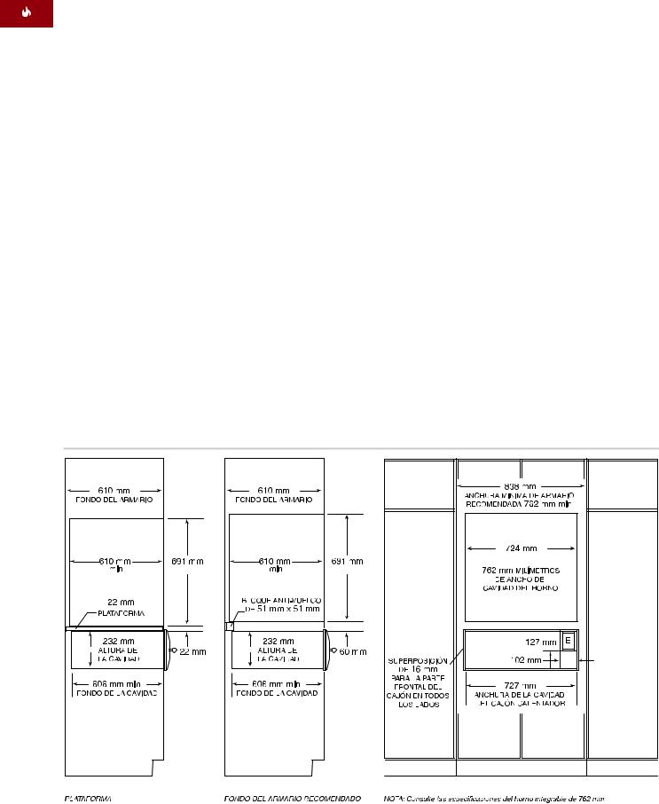
The Wolf warming drawer with stainless steel drawer front may be installed below or above a Wolf 762 mm built-in single oven or below a double oven, provided the warming drawer is fully enclosed, top and bottom. Refer to the illustration below. Also refer to installation instructions provided with the built-in oven for additional specifications. Dimensions will vary according to the specific installation.
The Wolf warming drawer is designed and agency approved for installation with Wolf built-in ovens.
The warming drawer platform must be able to support 91 kg. It must be a minimum of 25 mm above the toe kick to allow for the overlap of the warming drawer trim.
IMPORTANT NOTE: Additional clearance between warming drawer and oven openings may be required. Check that oven supports do not obstruct the interior dimensions required for the warming drawer.
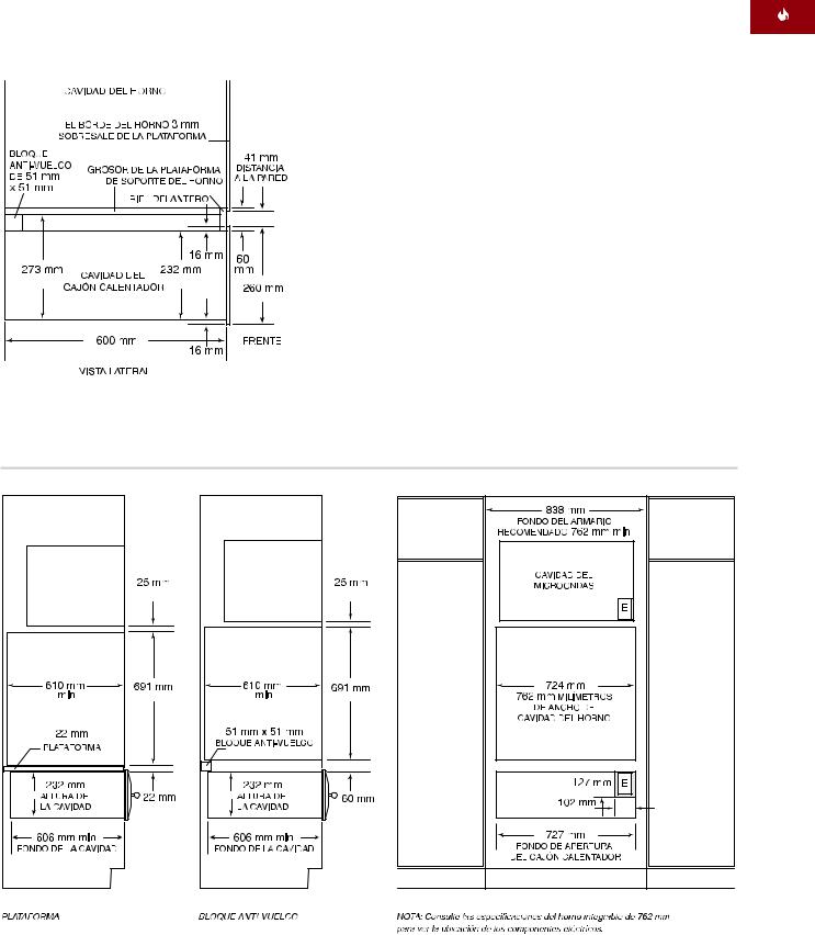
When the warming drawer is installed below a built-in oven, a minimum of 60 mm between warming drawer and oven openings is required for placement of the anti-tip block. To allow the warming drawer trim and the built-in oven trim to meet, a 22 mm platform may be used to separate the two openings. This will act as the support platform for the oven and the anti-tip device for the warming drawer. Both applications are shown in the
illustration below.
IMPORTANT NOTE: When the warming drawer is installed above a built-in oven, a 22 mm platform is required to allow for clearance of overlaps.
Installation with Built-In Oven – Stainless Steel Drawer Front
8

I N S TA L L AT I O N INSTRUCTIONS
S TA I N L E S S S T E E L DRAWER FRONT
Installation with Built-In Oven – Stainless Steel Drawer Front
OPTIONAL INSTALLATIONS
The Wolf warming drawer with stainless steel drawer front may be installed in combination with a 762 mm single oven and microwave oven with 762 mm trim, provided the warming drawer is fully enclosed, top and bottom. Refer to the illustration below. Also refer to installation instructions provided with the built-in oven and microwave for additional specifications. Dimensions will vary according to the specific installation.
The warming drawer platform must be able to support 91 kg. It must be a minimum of 25 mm above the toe kick to allow for the overlap of the warming drawer trim.
The Wolf warming drawer with stainless steel drawer front may be installed next to or above another Wolf warming drawer, provided each unit is fully enclosed, top and bottom.
Installation with Built-In Oven and Microwave – Stainless Steel Drawer Front
9
WOLF WA R M I N G D R AW E R
I N T E G R AT E D DRAWER FRONT
INSTALLATION SPECIFICATIONS
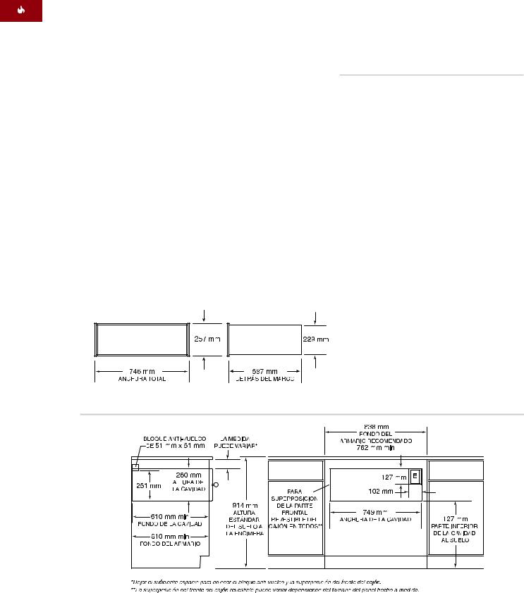
The following illustrations provide the overall dimensions and installation specifications for the Wolf warming drawer with integrated drawer front. The warming drawer with integrated drawer front can be used in an overlay application or an inset panel application where it will be completely recessed in to the cabinet.
Keep in mind that the size of the custom panel for the warming drawer with integrated drawer front will vary according to the specific installation. The following chart provides minimum dimensions for the overlay and inset panel applications.
Refer to pages 18–20 for integrated drawer front installation instructions. These instructions are also included with the integrated drawer front kit.
MODEL ICBWWD30 with Integrated Drawer Front
Overall Width |
|
746 mm |
Overall Height |
|
257 mm |
|
|
|
Overall Depth* (behind frame) |
597 mm |
|
|
|
|
Minimum Cabinet Requirements |
|
|
Overlay |
838 mm W x 610 mm D |
|
Inset |
838 mm W x 635 mm D |
|
|
|
|
Minimum Base Support |
91 kg mm |
|
|
|
|
Opening Width |
|
749 mm |
|
|
|
Opening Height |
|
260 mm |
|
|
|
Opening Depth** |
|
610 mm |
|
|
|
Minimum Panel Size |
|
|
Overlay |
762 mm W x 264 mm H |
|
Inset |
746 mm W x 257 mm H |
|
|
|
|
Minimum Panel Thickness |
16 mm |
|
|
|
|
Maximum Panel Weight |
11 kg |
|
|
|
|
*Allow 10 mm additional depth for cord thickness.
**For the inset application, add the thickness of the drawer face to the opening depth.
Overall Dimensions – Integrated Drawer Front
Integrated Drawer Front – Overlay Application
10
I N S TA L L AT I O N INSTRUCTIONS
I N T E G R AT E D DRAWER FRONT
OVERLAY APPLICATION
A minimum 838 mm wide by 610 mm deep cabinet is required for the warming drawer with integrated drawer front using the overlay application. A minimum base support of 91 kg is required. Refer to the illustration on page 10.
INSET APPLICATION
IMPORTANT NOTE: The inset application requires the warming drawer to be recessed into the cabinet. A minimum 635 mm deep cabinet is needed if you want the front panel to be flush with surrounding cabinetry.
If you are installing the warming drawer with integrated drawer front in an inset application, a minimum 838 mm wide and 635 mm deep cabinet is required for this installation. A minimum base support of 91 kg is required. Refer to the illustration below.
UNDERCOUNTER INSTALLATION
For undercounter installations, 597mm from the bottom of the warming drawer opening to the floor is recommended. It must be installed a minimum of 127 mm above the floor or
25 mm above the toe kick.
The Wolf warming drawer with integrated drawer front may be installed below a 762 mm or 914 mm wide electric or gas cooktop, provided the warming drawer is fully enclosed, top and bottom. Refer to installation instructions for the cooktop for additional specifications. Dimensions will vary according to the specific installation.
Integrated Drawer Front – Inset Application
11
WOLF WA R M I N G D R AW E R
I N T E G R AT E D DRAWER FRONT
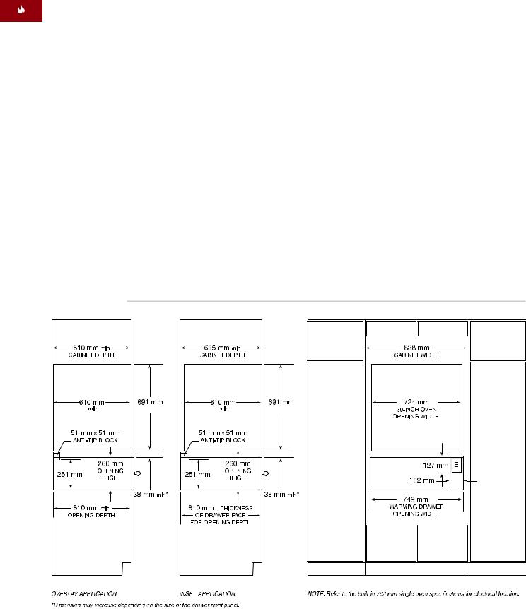
INSTALLATION WITH BUILT-IN OVEN
The Wolf warming drawer with integrated drawer front may be installed below or above a Wolf 762 mm or 914 mm built-in single oven, provided the warming drawer is fully enclosed, top and bottom. Refer to the illustration below. Also refer to installation instructions provided with the built-in oven for additional specifications. Dimensions will vary according to the specific installation.
The Wolf warming drawer is designed and agency approved for installation with Wolf built-in ovens.
The warming drawer platform must be able to support 91 kg. It must be a minimum of 25 mm above the toe kick to allow for the overlap of the warming drawer trim.
IMPORTANT NOTE: Additional clearance between warming drawer and oven openings may be required. Check that oven supports do not obstruct the interior dimensions required for the warming drawer.
When the warming drawer is installed below a built-in oven, a minimum of 38 mm between warming drawer and oven openings is
required for placement of the anti-tip block and oven platform. When installed above a built-in oven, a minimum of 22 mm is required.
IMPORTANT NOTE: In an overlay application, the amount of space between warming drawer and built-in oven openings may need to be increased depending on the size of the overlay panel and the amount of overlap.
Installation with Built-In Oven – Integrated Drawer Front
12
I N S TA L L AT I O N INSTRUCTIONS
I N T E G R AT E D DRAWER FRONT
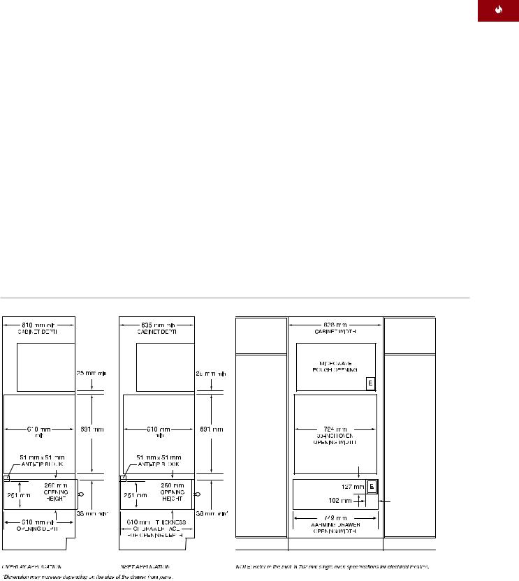
INSTALLATION OPTIONS
The Wolf warming drawer with integrated drawer front may be installed in combination with a 762 mm single built-in oven and microwave with 762 mm trim, provided the warming drawer is fully enclosed, top and bottom. Refer to the illustration below.
The Wolf warming drawer with integrated drawer front may also be installed in combination with a 914 mm single built-in oven and microwave with 914 mm trim.
The warming drawer platform must be able to support 91 kg. It must be a minimum of 25 mm above the toe kick to allow for the overlap of the warming drawer trim.
Refer to installation instructions provided with the built-in oven and microwave for additional specifications. Dimensions will vary according to the specific installation.
The Wolf warming drawer with integrated drawer front may be installed next to or above another Wolf warming drawer, provided each unit is fully enclosed, top and bottom.
Installation with 762 mm Built-In Oven and Microwave – Integrated Drawer Front
13
IMPORTANT NOTE
You must follow all local codes and ordinances when installing your service.
WOLF WA R M I N G D R AW E R
E L E C T R I C A L REQUIREMENTS
The Wolf warming drawer requires a separate, grounded 220–240 V AC, 50/60 Hz power supply and must be connected to an individual properly grounded branch circuit and protected by a 15 or 20 amp circuit breaker or time delay fuse.
IMPORTANT NOTE: The warming drawer must be plugged into a mating 3-prong grounding-type electrical cord to minimize the possibility of electric shock.
If the outlet is placed behind the unit, make sure the outlet is flush with the back wall. For location of the electrical outlet, refer to the installation illustration for your specific installation on pages 7–13.
If two warming drawers are installed side by side, they can operate from the same electrical outlet. A 30 amp circuit breaker is required for this installation.
In addition, be aware of local codes and ordinances when installing your service.
The electrical outlet must be checked by a qualified electrician to be sure that it is wired with the correct polarity. Verify that the outlet provides 220 –240 V AC and is properly grounded.
Do not use an extension cord or twoprong adapter. Electrical ground is required on this appliance. Do not remove the power supply cord ground prong.
14

I N S TA L L AT I O N INSTRUCTIONS
C A B I N E T SUPPORTS
IMPORTANT NOTE: When the warming drawer is installed with a built-in oven, additional clearance between openings may be required. Check that oven supports do not obstruct the interior dimensions required for the warming drawer.
The warming drawer with stainless steel drawer front may be supported by either a solid platform, 51 mm x 51 mm runners or 51 mm x 102 mm runners. The platform or runners must be level, rigidly mounted and flush with the bottom edge of the opening. They must be able to support 91 kg.
If an integrated drawer front is used, it must be supported by a 16 mm solid platform. The platform will need to be recessed and allow for overlap of the warming drawer collar. Refer to page 18 for additional details. The platform must be level, rigidly mounted and must be able to support 91 kg.
IMPORTANT NOTE: Make sure that the platform or runners are level. There is no way to level the warming drawer once it has been installed.
U N PA C K THE WARMING DRAWER
Unpack the warming drawer on a flat surface. Remove all packaging materials and tape from inside the warming drawer and discard. Do not discard the package containing the two wood screws needed for installation.
15
WOLF WA R M I N G D R AW E R
S TA I N L E S S S T E E L FRONT PANEL
INSTALL ANTI-TIP BLOCKING
An anti-tip block or platform must be installed to prevent the warming drawer from tipping forward while opened when loaded. Failure to do so could result in personal injury and damage to the cabinet.
Install a 51 mm x 51 mm or 51 mm x 102 mm anti-tip block against the rear cabinet wall. When the warming drawer is installed below a built-in oven, you may use a 22 mm thick platform to allow the warming drawer trim and the oven trim to meet. The platform will act as an anti-tip device for the warming drawer. Both applications are shown in the illustrations on page 8.
INSTALL WARMING DRAWER TRIM
Remove all packaging materials from the trim. The stainless steel drawer front kit comes with two long trim pieces for the top and bottom collar of the warming drawer and two short trim pieces for the sides. Each trim piece has a groove that fits over the edge of the collar. Refer to the illustration below.
Place one of the long trim pieces on the top collar of the warming drawer so the groove in the trim fits on the top collar.
Next, place one of the small side trim pieces on the left collar edge. The top trim and side trim should nest together. On the backside of the trim pieces are mounting holes. Use the small 8 mm long screws provided in the kit to secure these two pieces together.
Repeat this process to attach the right side and bottom trim.
Install warming drawer trim
16
I N S TA L L AT I O N INSTRUCTIONS
S TA I N L E S S S T E E L FRONT PANEL
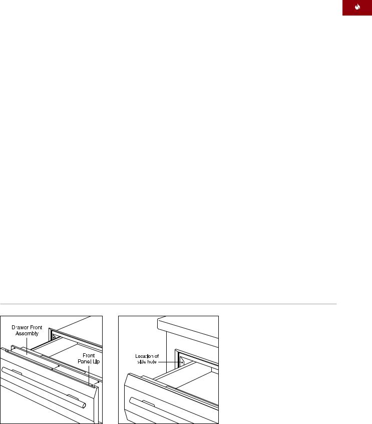
INSTALL FRONT PANEL
Remove all packaging materials from the handle and front panel. Gently remove the protective covering from the stainless steel front panel. The adhesive covering should peel away from the surface cleanly, but any remaining residue should be cleaned off with a mild detergent.
To attach the handle to the front panel, line up holes in the standoffs and handle with holes on the front panel. Insert handle screws through the holes in the front panel and tighten screws to the front panel.
Slide the top lip of the front panel over the drawer front. Insert three screws in the top of the front panel lip through the drawer front assembly and tighten screws. Insert three screws in the bottom of the front panel through the drawer front assembly and tighten screws. Refer to the illustration below.
Turn power off to the electrical outlet.
INSTALL WARMING DRAWER
Slide the left corner of the warming drawer into the opening. If the electrical outlet is installed inside the opening, plug the power cord into the outlet. The excess cord should be coiled behind or beside the unit. If the outlet is located in an adjacent cabinet, thread the power cord through the hole in the cabinet wall. Push the drawer back into the opening until the trim meets the cabinet front. Make sure the power cord does not get trapped under the warming drawer.
IMPORTANT NOTE: Do not lift up on the handle to push the drawer into place. Doing so could scratch the control panel.
Open the warming drawer to its full extension. Drill pilot holes in each side hole, located toward the front on each side of the warming drawer. Install the wood screws provided with the unit. Refer to the illustration below.
Turn power back on to the electrical outlet.
Attach handle |
Warming drawer installation |
17
WOLF WA R M I N G D R AW E R
I N T E G R AT E D FRONT PANEL
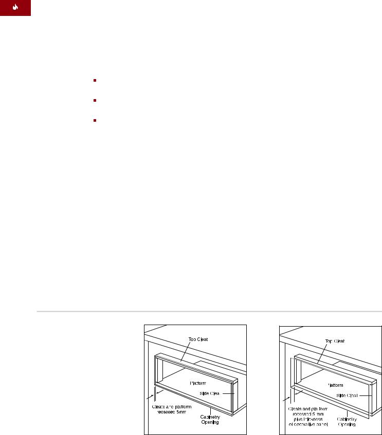
INSTALL CLEATS AND PLATFORM
For an overlay or inset application, you will need to install a recessed platform and cleats of the following dimensions into the opening.
Top Cleat Dimensions
749 mm W x 13 mm H x 51 mm D
Side Cleat Dimensions
13 mm W x 232 mm H x 51 mm D
Platform Dimensions
749 mm W x 16 mm H x 603 mm D
Depth of platform may increase depending cabinet depth.
For an overlay application, the platform and cleats will need to be recessed 5 mm. For an inset application, they must be recessed 5 mm plus the thickness of the decorative drawer panel, allowing the decorative panel to be flush with the front of the cabinet. Be sure to rigidly mount the platform so that it can support a minimum of 91 kg. Refer to the illustrations below.
IMPORTANT NOTE: In an overlay application, be sure to recess the cleats no more than
5 mm. Recessing deeper than this may cause the drawer to not close properly.
IMPORTANT NOTE: Be sure to finish the inside lip of the opening and the front face of the shelf and cleats. Some of these areas will be visible when the drawer is open.
IMPORTANT NOTE: Be aware of the location of the mounting holes on the warming drawer frame to make sure the screws used to attach the cleats do not interfere with the screw holes for mounting the warming drawer.
Recessed cleats and platform – overlay application
Recessed cleats and platform – inset application
18
I N S TA L L AT I O N INSTRUCTIONS
I N T E G R AT E D FRONT PANEL
INSTALL ANTI-TIP BLOCKING
Install a 51 mm x 51 mm or 51 mm x 102 mm anti-tip block against the rear cabinet wall as shown in the installation illustration for your specific installation on pages 11–13.
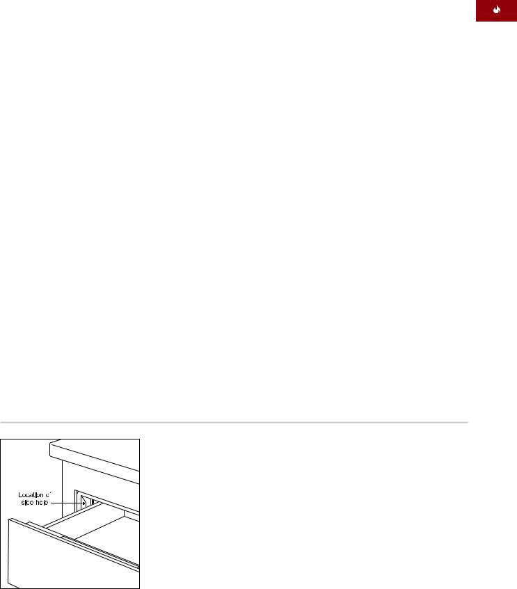
INSTALL WARMING DRAWER
Turn power off to the electrical outlet. Slide the left corner of the warming drawer into the opening. If the electrical outlet is installed inside the opening, plug the power cord into the outlet. The excess cord should be coiled behind or beside the unit. If the outlet is located in an adjacent cabinet, thread the power cord through the hole in the cabinet wall. Push the unit back into the opening until the warming drawer collar meets up with the recessed cleats and platform. Make sure the power cord does not get trapped under the warming drawer.
Open the drawer to its full extension. Drill pilot holes in each side hole, one located toward the front on each side of the warming drawer. Install the wood screws provided with the warming drawer. Refer to the illustration below. Turn power back on to the electrical outlet.
Warming drawer installation
19
WOLF WA R M I N G D R AW E R
I N T E G R AT E D FRONT PANEL
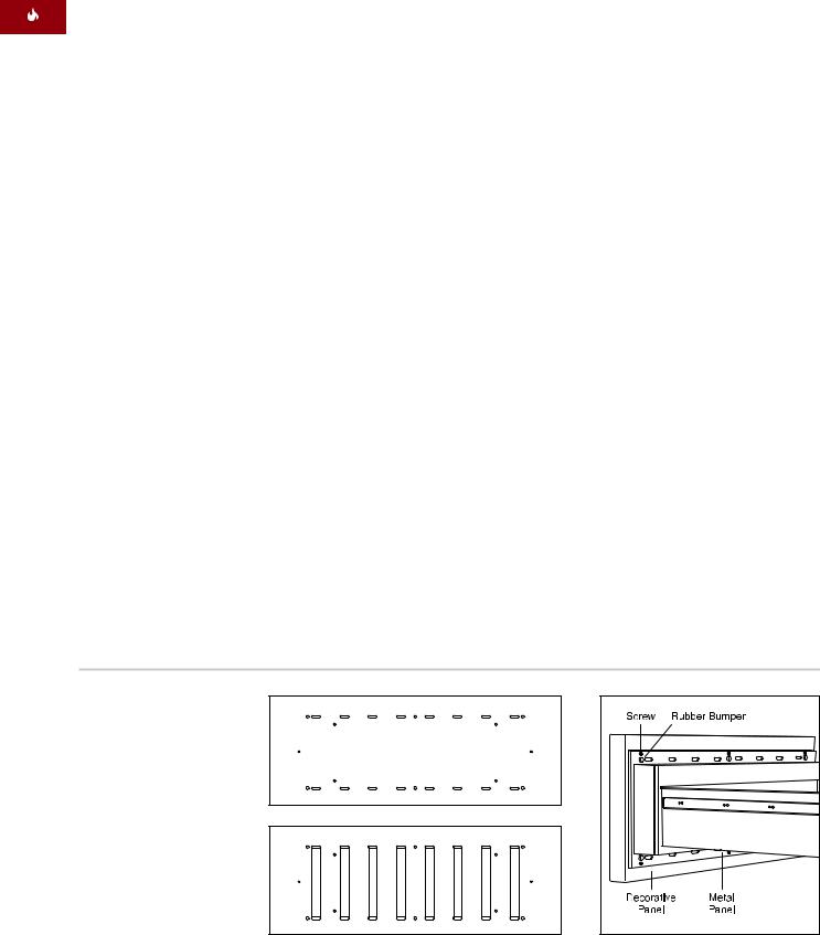
INSTALL FRONT PANEL TO DRAWER
Disconnect the communications line from communications jack. The communications jack is removed by depressing retaining clip from front of mounting panel, then pushing the retaining clip side of jack through mounting panel first, then pivoting jack out of mounting panel. Place removed communications jack inside drawer frame assembly.
Place the metal panel from the integrated drawer front onto the back of the decorative front panel. Trace all of the holes in the metal panel onto the decorative panel.
Draw a line from the edge of the oblong holes to the corresponding oblong hole below it. The markings on the back of the decorative panel should look like the bottom panel illustration below.
For every round marking on the decorative panel (12 locations, six for screw heads and six for the backs of the rubber bumpers), drill a 12.7 mm hole, 6.35 mm deep in the back of the panel.
Route out the rectangular areas (8 locations) marked on the back of the decorative panel 6.35 mm deep.
Attach the handle hardware to the front of the decorative panel. The integrated drawer front kit does not include a handle. This allows the homeowner to match handle hardware with the surrounding cabinetry.
Using the six screws that came with the warming drawer, install the metal panel from the integrated drawer front kit onto the warming drawer front. Make sure the brushed side of the metal panel is facing the warming drawer.
Install the six rubber bumpers, provided with the warming drawer front kit, onto the metal panel. Attach the decorative panel to the warming drawer by screwing through the back of the warming drawer into the decorative front panel using the six, 12.7 mm mounting screws provided with the kit.
Back view of decorative panel |
Location of bumpers and mounting |
|
screws |
20
I N S TA L LAT I ON INSTRUCTIONS
T R O U B L E SHOOTING |
IF YOU NEED S E RV I C E |
IMPORTANT NOTE: If the warming drawer does not operate properly, follow these troubleshooting steps:
Verify that power is being supplied to the warming drawer.
Check electrical connections to ensure that the installation has been completed correctly.
Refer to the Troubleshooting Guide in the Wolf Warming Drawer Use & Care Information.
If the warming drawer still does not work, contact your Wolf dealer or regional distributor. Do not attempt to repair the warming drawer yourself.
For service in your area, contact either your Wolf dealer or visit the Locator page of our website, wolfappliance.com to find the regional distributor by country.
When calling for service, you will need the model and serial numbers of the warming drawer. Both numbers are listed on the product rating plate, located on the left front floor area of the inner cabinet. To access the rating plate, the drawer must be fully open. Refer to the illustration on page 5.
The information and images are the copyright property of Wolf Appliance, Inc., an affiliate of Sub-Zero, Inc. Neither this book nor any information or images contained herein may be copied or used in whole or in part without the express written permission of Wolf Appliance, Inc., an affiliate of Sub-Zero, Inc.
©Wolf Appliance, Inc. all rights reserved.
CONTACT
INFORMATION
Website:
wolfappliance.com
21
INFORMACIÓN
DE CONTACTO
Página Web: wolfappliance.com
A medida que siga las instrucciones que aparecen en esta guía, encontrará símbolos de ADVERTENCIA y PRECAUCIÓN. Esta información en recuadros es importante para instalar el equipo de Wolf de forma segura
y eficaz. Existen dos tipos de posibles riesgos que pueden producirse durante una instalación.
indica una situación en la que pueden producirse heridas personales leves o daños secundarios en el producto si no se siguen las instrucciones.
indica que existe peligro de que se produzcan heridas personales graves o incluso puede provocar la
muerte si no se siguen las instrucciones.
Otro tipo de anotación que nos gustaría indicar es la que se incluye en NOTA IMPORTANTE: En esta nota se resalta la información que resulta especialmente importante para que la instalación se realice sin problemas.
WOLF® es una marca comercial registrada de Wolf Appliance, Inc.
C A J Ó N C A L E N TA D O R DE WOLF
REQUISITOS DE I N S T A L A C I Ó N
NOTA IMPORTANTE: Esta instalación debe ser realizada por un técnico cualificado.
Instalador: Lea las instrucciones de instalación antes de llevar a cabo la instalación. Guarde estas instrucciones para que el inspector local pueda utilizarlas como refe-rencia y, a continuación, entréguelas al propietario del aparato.
Propietario: Lea y guarde estas instrucciones para que pueda utilizarlas como referencia en el futuro y asegúrese de leer la guía de uso y mantenimiento antes de utilizar el aparato.
Si tiene alguna pregunta o problema relacionado con la instalación, debe ponerse en contacto con su distrubuidor de Wolf.
También puede visitar nuestra página Web wolfappliance.com.
NOTA IMPORTANTE: Este aparato debe ser instalado siguiendo las normativas nacionales correspondientes. Se debe aplicar al aparato el voltaje, la frecuencia y el amperaje adecuados desde una instalación eléctrica resistente con toma de tierra protegida por un fusible de retardo. El voltaje, la frecuencia y el amperaje se muestran en la placa de datos del producto.
Apunte la referencia del modelo y el número de serie antes de instalar el cajón calentador. Esta información aparece en la placa de datos del producto situada en la parte izquierda delantera del mueble interior. Para ver la placa de datos, es necesario abrir el cajón totalmente. Observe la siguiente ilustración.
Referencia del modelo ICBWWD30
Número de serie
Modelo ICBWWD30 con frente de cajón de acero inoxidable
Modelo ICBWWD30 con frente de cajón que lleve un panel integrado
Ubicación de |
la placa de |
datos |
Ubicación de la placa de datos
23
ACCESORIOS
Podrá disponer de los accesorios opcionales en el distribuidor de Wolf correspondiente.
C A J Ó N C A L E N TA D O R DE WOLF
A N T E S DE COMENZAR
Antes de instalar el cajón calentador, asegúrese de que tiene preparado el frente de cajón de Wolf para que sea instalado.
NOTA IMPORTANTE: Si está instalando el cajón calentador con el frente integrado para un uso empotrado, asegúrese de que el mobiliario cumple las medidas mínimas de 838 mm de ancho y 635 mm de fondo.
Consulte la normativa eléctrica correspondiente a su área con los servicios públicos locales. La normativa local puede variar.
La instalación, las conexiones eléctricas y la conexión a tierra deben cumplir la normativa aplicable.
Este aparato debe estar conectado a tierra de manera correcta. Consulte la sección Requisitos eléctricos en la página 32.
Compruebe que tiene las herramientas y los materiales necesarios para realizar la instalación de manera correcta.
OPCIONES DEL F R E N T E D E C A J Ó N
NOTA IMPORTANTE: El modelo ICBWWD30 debe instalarse con un panel frontal integrado o un frente de acero inoxidable de Wolf.
|
Acero inoxidable |
WWDFRONT/S |
|
||
|
Frente de cajón integrado |
WWDFRONT/I |
|
||
|
(admite panel de madera) |
|
Los frentes de cajón se piden y se envían como accesorios e incluyen instrucciones de instalación adicionales. Los frentes de
cajón de acero inoxidable incluyen un tirador tubular a juego.
El frente de cajón integrado admite un panel de madera fabricado a medida y un tirador que tendrá que elegir a parte el propietario. También hay disponibles tiradores tubulares de acero inoxidable como accesorios opcionales.
H E R R A M I E N TA S Y M AT E R I A L E S
NECESARIOS
Tornillos de madera u otras piezas para instalar la plataforma o las guías de deslizamiento que sujetan el cajón calentador
Listones de 51 mm x 51 mm ó 51 mm x 102 mm para las guías de desplazamiento que deben aguantar un peso de 91 kg
Listones de 51 mm x 51mm ó
51 mm x 102 mm para el bloque anti-vuelco
Sierra mecánica
Nivel
Taladro y broca de 1,58 mm, broca de 12,7 mm también para la aplicación del frente de cajón integrado
Destornillador Phillips
2 tornillos de madera (incluidos)
Listón de madera para el frente de cajón integrado
24
INSTRUCCIONES DE I N S TA L A C I Ó N
FRENTE DE CAJÓN DE A C E R O
I N OX I DA B L E
ESPECIFICACIONES DE LA
INSTALACIÓN
La siguiente ilustración proporciona las medidas totales y las especificaciones de la instalación para el cajón calentador de Wolf con el frente de acero inoxidable.
Wolf le recomienda utilizar un mueble con un ancho de 838 mm para el cajón calentador con el frente de acero inoxidable. Se requiere un mueble con unas medidas de 762 mm de ancho por 610 mm de fondo con una base que soporte un mínimo de 91 kg.
Consulte las páginas 34–35 para obtener las instrucciones de instalación del frente de cajón de acero inoxidable. Estas instrucciones también se incluyen con el kit del frente de cajón de acero inoxidable.
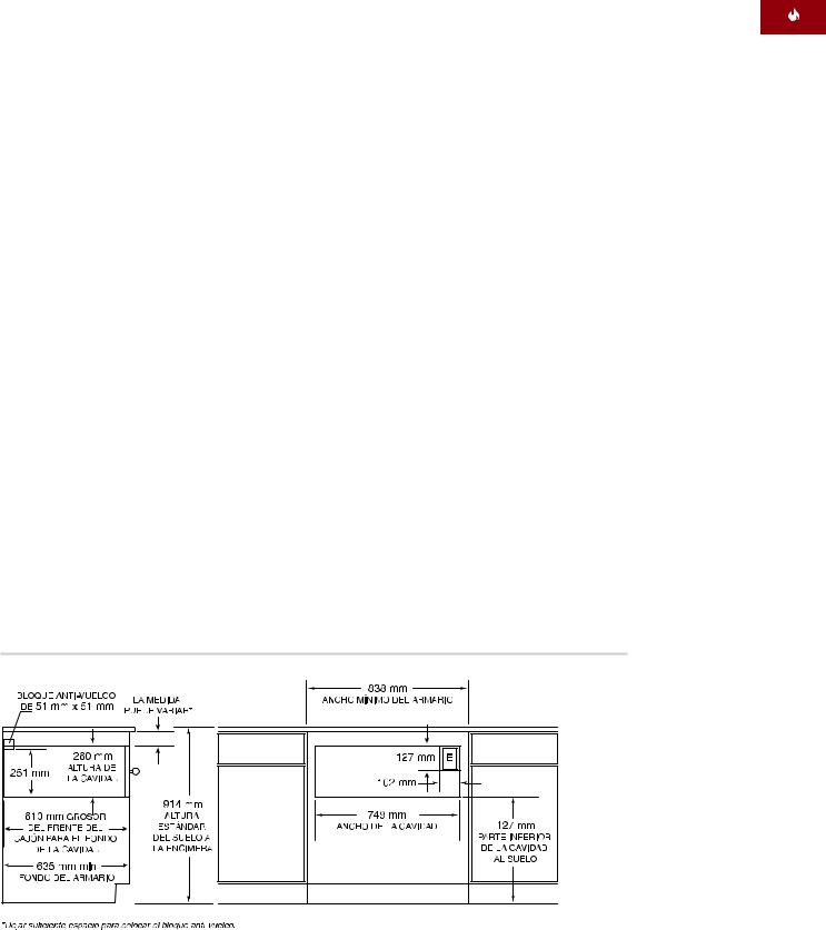
INSTALACIÓN BAJO ENCIMERA
Para instalar el cajón bajo una encimera, se recomienda mantener una espacio de 597 mm desde la parte inferior del cajón calentador hasta el suelo. El cajón debe instalarse con un mínimo de 127 mm sobre el nivel del suelo ó 25 mm sobre el rodapié.
El cajón calentador con frente de acero inoxidable puede instalarse debajo de un cocina de gas o de una placa vitrocerámica siempre que el cajón calentador quede completamente ajustado en la parte superior e inferior. Deje el suficiente espacio para las conexiones eléctricas o de gas de la cocina. Consulte las instrucciones de instalación de la cocina para obtener especificaciones adicionales. Las medidas puede variar dependiendo de la instalación.
MODELO ICBWWD30
con frente de cajón de acero inoxidable
Ancho total |
759 mm |
Altura total |
260 mm |
|
|
Fondo total |
689 mm |
|
|
Fondo detrás del marco* |
597 mm |
|
|
Ancho mínimo del mueble |
762 mm |
|
|
Fondo mínimo del mueble |
610 mm |
|
|
Soporte mínimo de la base |
91 kg |
|
|
Ancho de la cavidad |
727 mm |
|
|
Altura de la cavidad |
232 mm |
|
|
Fondo de la cavidad |
606 mm |
|
|
*Deje un fondo adicional de 10 mm para el cable.
Dimensiones totales: Frente de cajón de acero inoxidable
25
Instalación bajo encimera: Frente de cajón de acero inoxidable
C A J Ó N C A L E N TA D O R DE WOLF
FRENTE DE CAJÓN DE AC E R O
I N OX I DA B L E
INSTALACIÓN CON HORNO
INTEGRABLE
El cajón calentador de Wolf con frente de acero inoxidable puede instalarse debajo de o sobre un horno sencillo integrable de 762 mm o debajo de un horno doble siempre que el cajón calentador quede completamente ajustado en la parte superior e inferior. Observe la siguiente ilustración. Consulte también las instrucciones de instalación
que se proporcionan con el horno integrable para obtener especificaciones adicionales. Las medidas puede variar dependiendo de cada instalación.
El cajón calentador de Wolf está diseñado y aprobado por el organismo regulador corres-pondiente para que se pueda instalar con hornos integrables de Wolf.
La plataforma del cajón calentador debe aguantar un peso de 91 kg. Debe dejar un espacio mínimo de 25 mm por encima del rodapié para dejar un margen suficiente para la superoposición del borde del cajón calentador.
NOTA IMPORTANTE: Se necesita dejar un espacio adicional entre la cavidad del cajón calentador y del horno. Compruebe que los soportes del horno no obstruyen las medidas interiores requeridas para el cajón calentador.
Cuando instale el cajón calentador debajo de un horno integrable, necesitará dejar un espacio mínimo de 60 mm entre la cavidad
del cajón calentador y la del horno para poder colocar el bloque anti-vuelco. Para que el borde del cajón calentador y el borde del horno integrable queden unidos, puede utilizar una plataforma de 22 mm entre las dos aperturas. Esta plataforma actúa como una plataforma de soporte para el horno y el dispositivo anti-vuelco lo hace para el cajón calentador. Ambos usos se muestran en la siguiente ilustración.
NOTA IMPORTANTE: Cuando el cajón calentador se instala sobre el horno integrable, es necesario colocar una plataforma de 22 mm para dejar suficiente margen para las superposiciones.
26 


 Instalación con horno integrable – Frente de cajón de acero inoxidable
INSTRUCCIONES DE I N S TA L A C I Ó N
FRENTE DE CAJÓN DE A C E R O
I N O X I D A B L E
Instalación con horno incorporado: frente de cajón de acero inoxidable
INSTALACIONES OPCIONALES
El cajón calentador de Wolf con frente de acero inoxidable puede instalarse en combinación con un horno sencillo de 762 mm y con un microondas con un borde de 762 mm siempre que el cajón calentador quede completamente ajustado a la parte superior e inferior. Observe la siguiente ilustración. Consulte también las instrucciones de instalación que se proporcionan con el horno integrable y el microondas para obtener especificaciones adicionales. Las medidas pueden variar dependiendo de cada instalación.
La plataforma del cajón calentador debe aguantar un peso de 91 kg. Debe dejar un mínimo de 25 mm por encima del rodapié para que haya suficiente margen para la superposición del borde del cajón calentador.
El cajón calentador de Wolf con frente de acero inoxidable puede instalarse al lado de o debajo de otro cajón calentador de Wolf, siempre que el cajón calentador quede completamente ajustado al cerrarse en la parte superior e inferior.
Instalación con horno incorporado y microondas: frente de cajón de acero inoxidable
27
C A J Ó N C A L E N TA D O R DE WOLF
FRENTE DE CAJÓN I N T E G R A D O
ESPECIFICACIONES DE LA
INSTALACIÓN
Las siguientes ilustraciones proporcionan las medidas generales y las especificaciones de la instalación para el cajón calentador de Wolf con frente de acero inoxidable. El cajón calentador con frente integrado se puede utilizar en aplicaciones empotradas o revestible, por lo que el cajón quedará completamente acoplado en el mueble.
Recuerde que el tamaño del panel fabricado a medida para el cajón calentador con frente integrado puede variar dependiendo de cada instalación. La siguiente figura proporciona las medidas mínimas para el cajón revestido o empotrado.
Consulte las páginas 36-38 para observar las instrucciones de instalación del frente del cajón integrado. Estas instrucciones también se incluyen con el kit del frente del cajón integrado.
MODELO ICBWWD30 con frente de cajón integrado
Ancho total |
|
746 mm |
Altura total |
|
257 mm |
|
|
|
Fondo total* (marco posterior) |
597 mm |
|
|
||
Requisitos mínimos del mueble |
||
Revestible |
|
838 A x 610 F |
Empotrado |
|
838 A x 635 F |
|
|
|
Soporte mínimo de la base |
91 kg |
|
|
|
|
Ancho de la cavidad |
|
749 mm |
|
|
|
Altura de la cavidad |
|
260 mm |
|
|
|
Fondo de la cavidad** |
|
610 mm |
|
|
|
Tamaño mínimo del panel |
|
|
Revestible |
762 A x 264 Altura |
|
Empotrado |
746 A x 257 Altura |
|
|
|
|
Grosor mínimo del panel |
|
16 mm |
|
|
|
Peso máximo del panel |
|
11 kg |
|
|
|
*Deje un fondo adicional de 10 mm para el cable.
**Para aplicaciones empotrables, sume el grosor de la parte delantera del cajón al fondo de la cavidad.
Medidas totales: frente de cajón integrado
Frente de cajón integrado: aplicación revestible
28
INSTRUCCIONES DE I N S TA L A C I Ó N
FRENTE DE CAJÓN I N T E G R A D O
APLICACIÓN REVESTIBLE
Se requiere un mueble con un ancho de
838 mm por un fondo de 610 mm mínimo para el cajón calentador con frente integrado si es una instalación revestible. Se requiere un soporte de base que aguante un peso de 91 kg mínimo. Consulte la ilustración de la página 28.
APLICACIÓN PARA EMPOTRAR
NOTA IMPORTANTE: Para empotrar el aparato en un mueble será necesario que el cajón calentador quede completamente
acoplado dentro del mueble. Si desea que el panel del frente se nivele con el mobiliario circundante, necesitará un mueble con un fondo mínimo de 635 mm.
Si desea empotrar el cajón calentador con el frente integrado, necesitará un mueble con un ancho de 838 mm y un fondo de 635 mm como mínimo para realizar este tipo de instalación. Se requiere un soporte de base que aguante un peso de 91 kg mínimo. Observe la siguiente ilustración.
INSTALACIÓN BAJO ENCIMERA
Para la instalación bajo encimera, se recomienda dejar un espacio de 597 mm desde la parte inferior del cajón calentador hasta el suelo. Debe instalarse con un mínimo de
127 mm sobre el nivel del suelo ó 25 mm sobre el rodapié.
El cajón calentador con frente integrado puede instalarse debajo de un cocina de gas o de una placa vitrocerámica con un ancho de 762 mm ó 914 mm siempre que el cajón calentador quede completamente ajustado al cerrarse, tanto en la parte inferior como en la parte superior. Consulte las instrucciones de instalación de la placa vitrocerámica para obtener especificaciones adicionales. Las medidas puede variar dependiendo de cada instalación.
Frente de cajón integrado: empotrado
29
 Loading...