

Wolf ICBSO24TE, ICBSO2418TE Installation Manual
GUÍA DE INSTALACIÓN
GUIDE D’INSTALLATION
GUIDA ALL’INSTALLAZIONE
INSTALLATIONSANLEITUNG
INSTALLATIEHANDLEIDING
61 cm E SERIES OVEN
INSTALLATION GUIDE
2 | English
61 cm E SERIES OVEN
Product Information
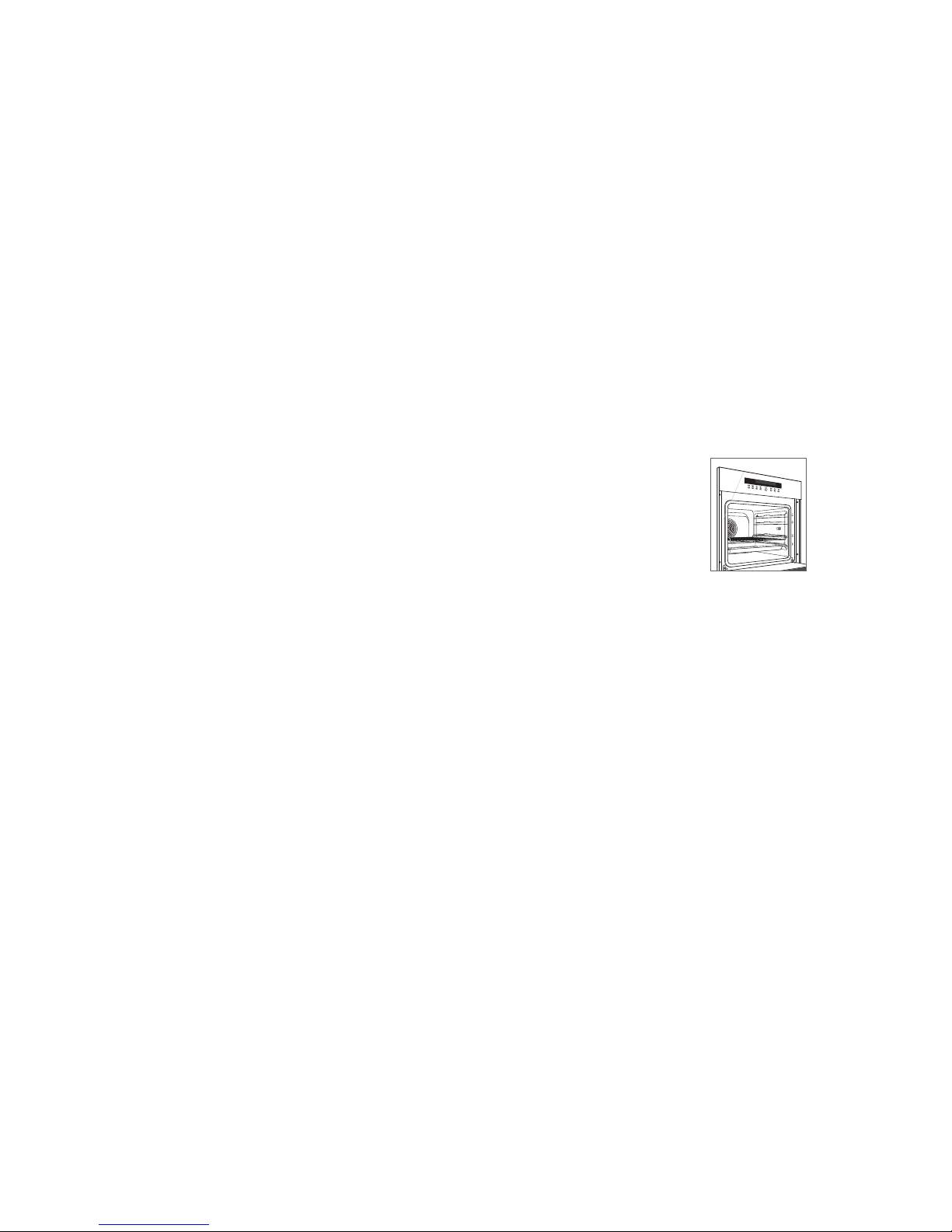
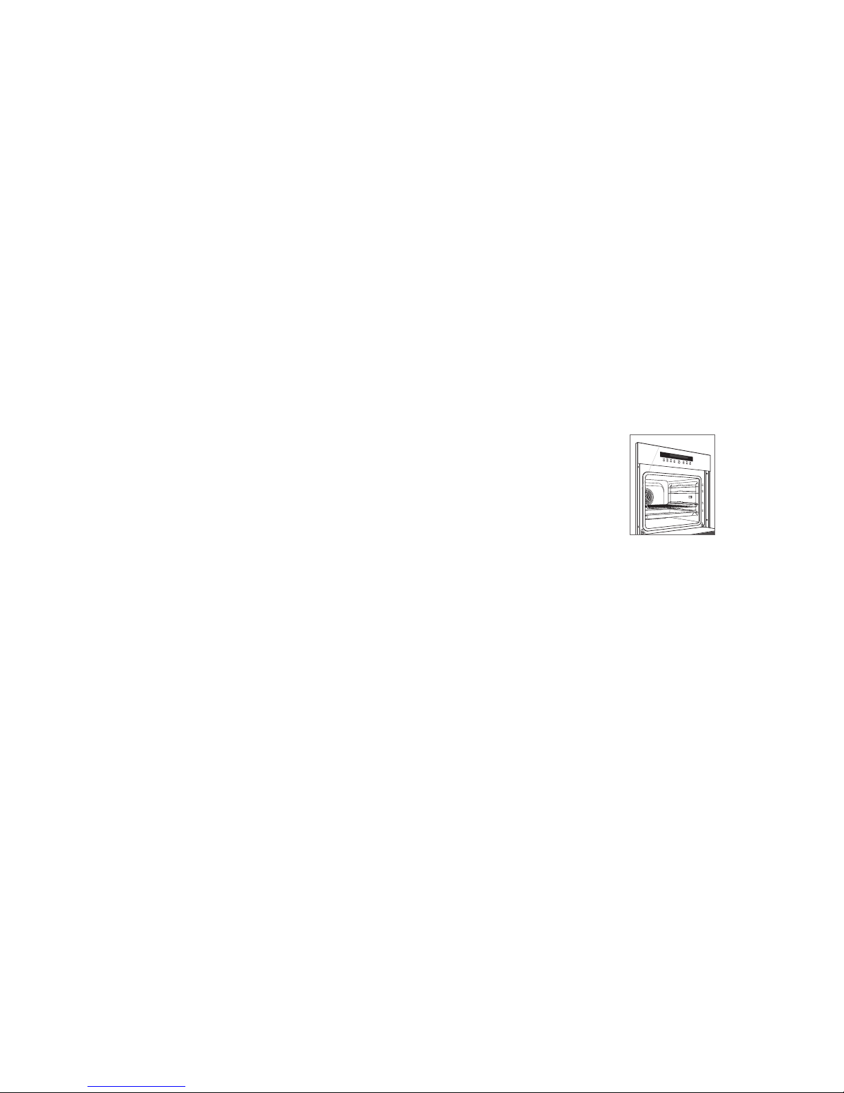
Important product information including the model and
serial number are listed on the product rating plate. The
rating plate is located on the left side of the front face frame.
The oven door must be open to view the rating plate. Refer
to the illustration below.
If service is necessary, contact Wolf factory certied service
with the model and serial number.
Contents
2 61 cm E Series Oven
3 Specications
5 Installation
5 Troubleshooting
Features and specications are subject to change at any
time without notice.
Important Note
To ensure this product is installed and operated as safely
and efciently as possible, take note of the following types
of highlighted information throughout this guide:
IMPORTANT NOTE highlights information that is especially
important.
CAUTION indicates a situation where minor injury or product
damage may occur if instructions are not followed.
WARNING states a hazard that may cause serious injury or
death if precautions are not followed.
IMPORTANT NOTE: Save these instructions for the local
electrical inspector.
Rating plate location.
RATING PLATE
wolfappliance.com | 3
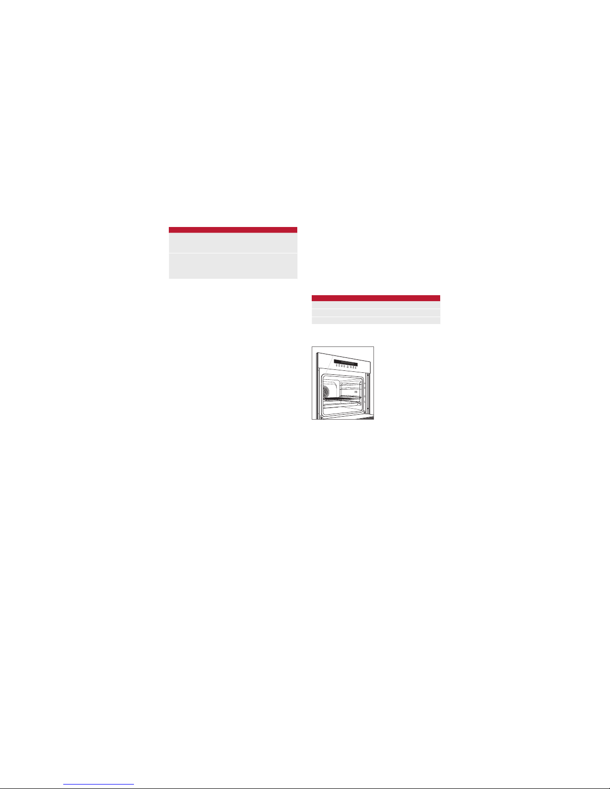
Electrical
Installation must comply with all applicable electrical codes
and be properly grounded (earthed).
The electrical supply must be placed in an adjacent cabinet
within reach of the 1.8 m power cord. Locate the electrical
supply as shown in the illustrations on the following pages.
A separate circuit, servicing only this appliance is required.
A ground fault circuit interrupter (GFCI) is not recommended
and may cause interruption of operation. Refer to the illustration below for minimum power cord plug clearance.
ELECTRICAL REQUIREMENTS
Electrical Supply 220-240 VAC, 50 Hz
Service 3400 Watts
Power Cord 1.8 m
SPECIFICATIONS
IMPORTANT NOTE:
Connection of this appliance should be
through a fused connection unit or a suitable isolator, which
complies with national and local safety regulations. The
on/off switch should be easily accessible after the appliance has been installed. If the switch is not accessible after
installation (depending on country) an additional means of
disconnection must be provided for all poles of the power
supply. When switched off there must be an all pole contact
gap of 3 mm in the isolator switch. This 3 mm contact disconnect gap must apply to any isolator switch, fuses and/or
relays according to EN60335.
Installation Requirements
The oven can be installed in a standard or ush inset
application. If a cooktop is being installed above the oven,
a minimum of 6 mm is required between units. Location of
the electrical supply within the oven opening may require
additional cabinet depth.
Finish the edges of the opening. They may be visible when
the door is open.
For standard installations, face trim will overlap stiles and
rails. Refer to the chart.
For ush inset installations, a minimum 3 mm reveal is
required on all sides. To ensure consistent reveals, each
corner of the opening must be exactly 90°.
INSTALLATION REQUIREMENTS
BASE SUPPORT MIN
ICBSO24TE 68 kg
ICBSO2418TE 45 kg
TRIM OVERLAP
Top 6 mm
Bottom 0 mm
Sides 17 mm
Rating plate location.
RATING PLATE
4 | English
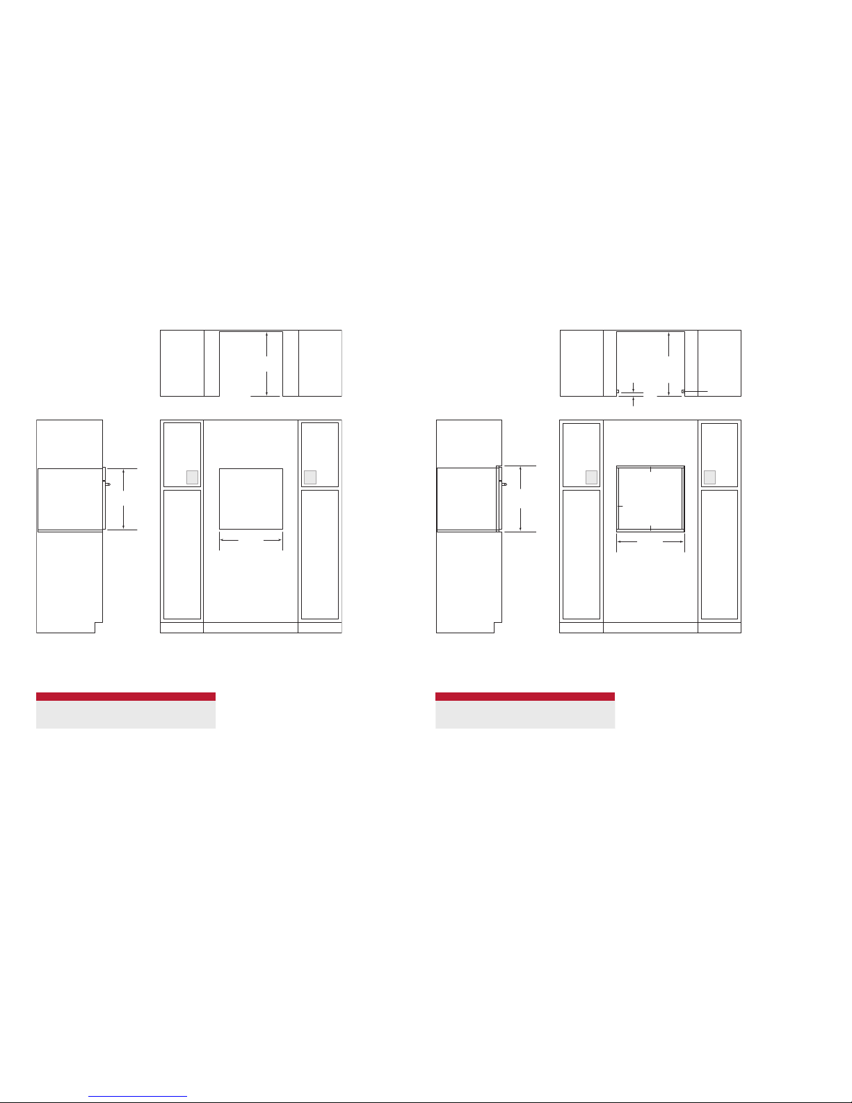
SPECIFICATIONS
603 mm
FLUSH INSET WIDTH**
FRONT VIEW
SIDE
VIEW
584 mm
FLUSH
INSET
DEPTH
22 mm
*W
ill be visible and should be finished to match cabinetry.
**
Dimension provides minimum reveals.
NOTE: Electrical supply must be located in adjacent cabinet within .9 m of opening.
H
FLUSH INSET
HEIGHT**
10 mm
3 mm
TOP VIEW
EE
21 mm
FINISHED
CLEATS*
61 cm E Series Oven
FLUSH INSET INSTALLATION
61 cm E Series Oven
STANDARD INSTALLATION
前视图侧视图
注:电源必须位于邻近机柜的0.9米开口的范围内。
H
开口高度
572 mm
开口深度
顶视图
562 mm
开口宽度
EE
OPENING HEIGHT
E SERIES OVEN H
ICBSO24TE 591 mm
ICBSO2418TE 449 mm
FLUSH INSET HEIGHT
E SERIES OVEN H
ICBSO24TE 603 mm
ICBSO2418TE 460 mm
wolfappliance.com | 5
INSTALLATION
Preparation
Before moving the oven, protect any nished ooring and
secure the oven door(s) closed to prevent damage.
Use an appliance dolly to move the unit near the opening.
Remove and recycle packing materials. Do not lift or carry
the oven by the door handle.
CAUTION
Do not lift the oven by the door handle. This will
damage the oven door and hinges.
Installation
Place the oven in the opening and slide back partially. Guide
the power cord through the opening of the adjacent cabinet
and slide oven back fully. Verify the power cord is not
trapped between the oven and cabinet wall.
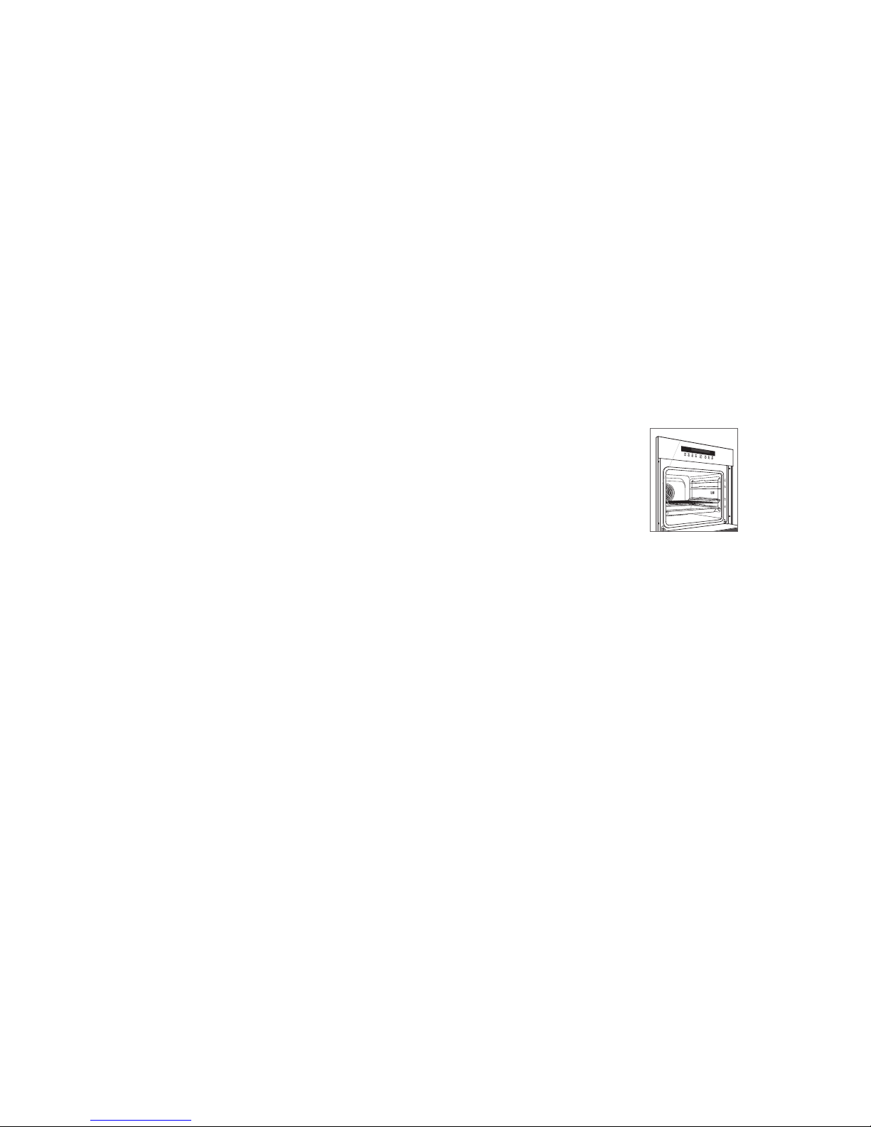
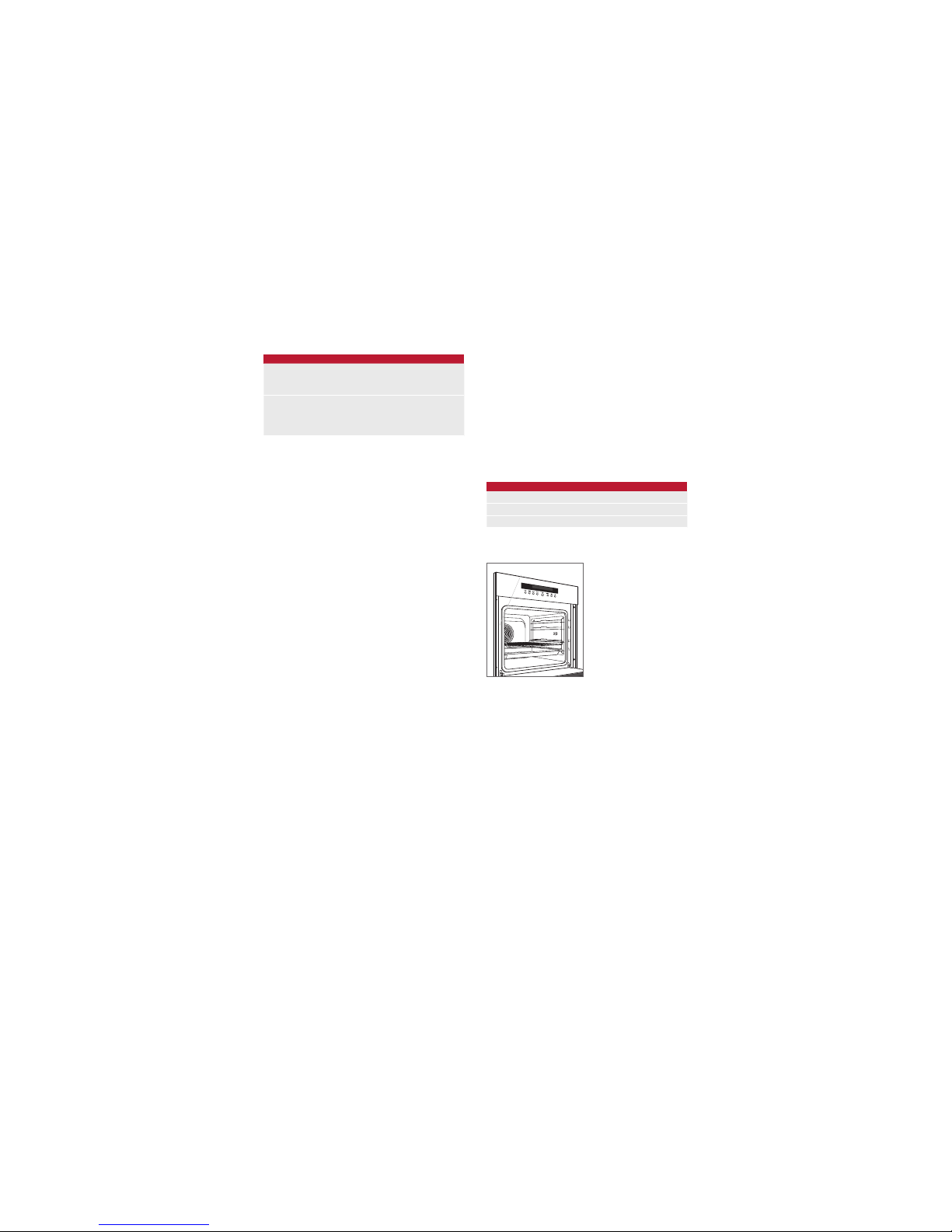
Locate mounting holes on the oven side trim, two on each
side. Drill pilot holes. Use the mounting screws provided to
secure the oven to cabinetry. Refer to the illustration below.
To avoid interference, a 90° door stop may be required for
any appliance or cabinet door installed next to the oven.
CAUTION
Failure to install the mounting screws may cause the
oven to tip forward during use.
MOUNTING
HOLES
Oven installation.
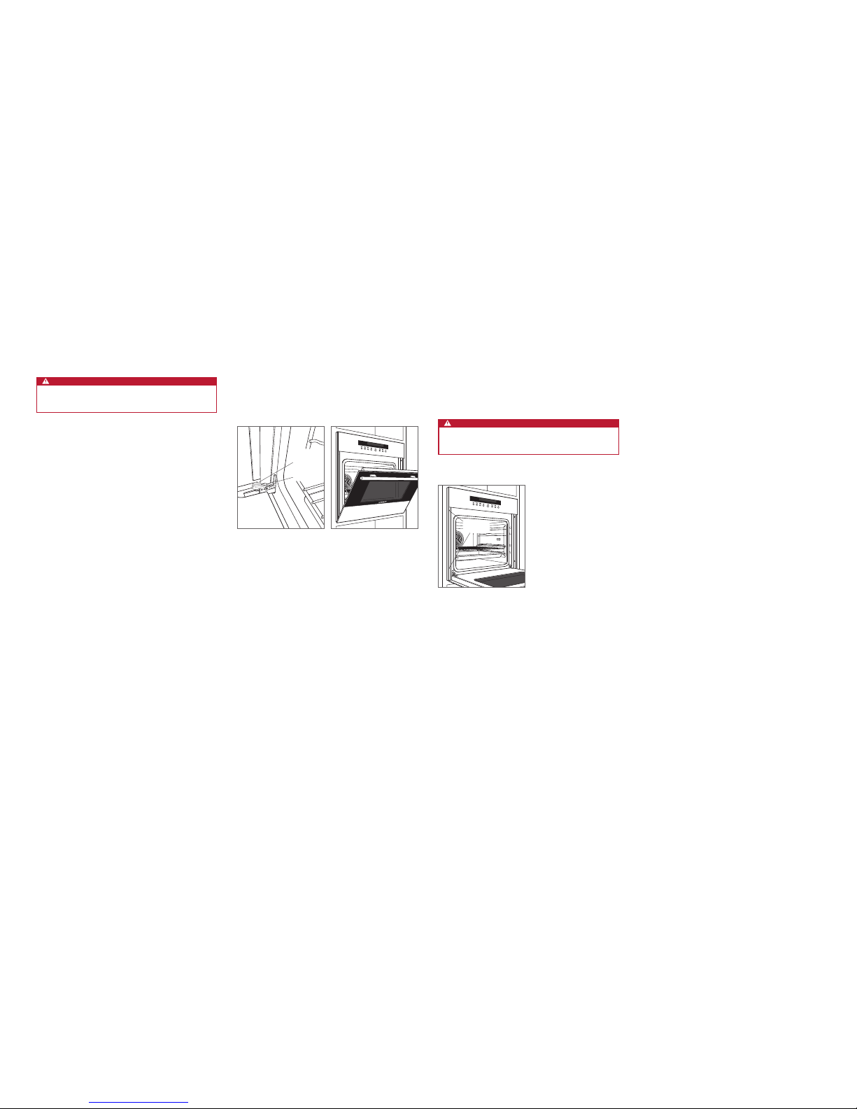
OVEN DOOR REMOVAL
To remove, open the oven door completely. Rotate both
hinge latches forward to the open position. Close door to
approximately 30° open, then lift up and out. Refer to the
illustrations below.
To reinstall, insert door hinges into the frame openings.
Open the oven door completely and rotate both hinge
latches back to the closed position.
OPEN
POSITION
CLOSED
POSITION
Oven door hinge latch.
Door open 30°.
Troubleshooting
IMPORTANT NOTE: If the oven does not operate properly,
follow these troubleshooting steps:
• Verify electrical power is supplied to the oven.
• Verify proper electrical connections.
• If the oven does not operate properly, contact Wolf
factory certied service. Do not attempt to repair the
oven. Wolf is not responsible for service required to
correct a faulty installation.
Sub-Zero, Sub-Zero & Design, Sub-Zero & Snowake Design, Dual Refrigeration, The Living Kitchen, Great American Kitchens The Fine Art of Kitchen Design, Wolf, Wolf & Design, Wolf Gourmet, W & Design, red colored knobs, Cove, and Cove & Design, are registered trademarks and service marks of Sub-Zero Group, Inc. and its subsidiaries.
All other trademarks are property of their respective owners in the United States and other countries.
2 | Español
HORNO DE LA SERIE E DE 61 cm
Información del producto
En la placa de datos del producto encontrará información
importante, incluyendo el modelo y el número de serie. La
placa de datos está ubicada en el lado izquierdo del marco
frontal. La puerta del horno debe estar abierta para ver la
placa de datos. Observe la siguiente ilustración.
Si necesita recurrir a un servicio técnico, póngase en contacto con un servicio de Wolf certicado con el modelo y el
número de serie.
Índice
2 Hornos de la serie E de 61 cm
3 Especicaciones
5 Instalación
5 Localización y solución de problemas
Las características y especicaciones están sujetas a cambios sin previo aviso.
Nota importante:
Para garantizar que este producto se instala y funciona de
la forma más ecaz y segura posible, tenga en cuenta la
información que se destaca en esta guía:
Cuando aparece
NOTA IMPORTANTE, se resalta información
que resulta especialmente importante.
PRECAUCIÓN indica una situación en la que se pueden
sufrir heridas leves o provocar daños al producto si no se
siguen las instrucciones.
AVISO indica el peligro de que se produzcan heridas graves
o incluso la muerte si no se respetan las precauciones.
NOTA IMPORTANTE: conserve estas instrucciones para el
inspector eléctrico local.
Ubicación de la placa de datos.
PLACA DE DATOS
wolfappliance.com | 3
Potencia
La instalación debe cumplir con todas las normativas eléctricas aplicables y debe estar correctamente conectada a
tierra.
La toma eléctrica debe colocarse en un armario contiguo
cerca del cable eléctrico. Ubique la toma eléctrica tal como
se muestra en las ilustraciones de las siguientes páginas.
Se necesita un circuito independiente para esta unidad. No
se recomienda utilizar un interruptor de circuito de fallos de
toma de tierra (GFCI), ya que puede interrumpir el funcionamiento de la unidad. Consulte en la siguiente ilustración el
espacio libre mínimo para el cable de alimentación.
REQUISITOS ELÉCTRICOS
Suministro eléctrico 220-240 VAC, 50 Hz
Servicio 3400 Vatios
Cable eléctrico 1,8 m
ESPECIFICACIONES
NOTA IMPORTANTE:
la conexión de este aparato debe realizarse a una unidad de conexión con fusibles o a un aislador
adecuado, que cumpla con las normativas de seguridad
nacionales y locales. El interruptor de encendido/apagado
debe encontrarse en un lugar accesible después de haber
instalado el aparato. Si no es posible acceder al interruptor
después de la instalación (según el país), se deberá suministrar un medio de desconexión adicional para todos los
polos de la alimentación eléctrica. Al estar desconectado,
deberá existir una separación de contacto entre todos los
polos de 3 mm en el interruptor del aislador. Esta separación de 3 mm de desconexión de los contactos deberá
aplicarse a cualquier interruptor, fusibles o relés del aislador
según la norma EN60335.
Requisitos de instalación
El horno puede instalarse en una aplicación estándar o de
encastre. Si la placa se va a instalar sobre un horno, es
necesario dejar un espacio mínimo de 6 mm entre las unidades. La ubicación de la toma eléctrica en la cavidad del
horno puede exigir un armario de mayor profundidad.
Remate los bordes de la cavidad, pues son áreas que
pueden resultar muy visibles al abrir la puerta.
Para instalaciones estándar, el contramarco frontal irá
superpuesto sobre los raíles y montantes. Consulte la tabla.
Para instalaciones empotrables, es necesario un margen
mínimo de 3 mm en todos los lados. Para garantizar unos
márgenes consistentes, cada esquina de la cavidad debe
tener exactamente 90º.
REQUISITOS DE INSTALACIÓN
SOPORTE DE LA BASE MÍN.
ICBSO24TE 68 kg
ICBSO2418TE 45 kg
SUPERPOSICIÓN DEL MARCO
Superior 6 mm
Inferior 0 mm
Lados 17 mm
Ubicación de la placa de datos.
PLACA DE DATOS

4 | Español
ESPECIFICACIONES
603 mm
ANCHURA DE INSTALACIÓN
ENCASTRADA**
VISTA FRONTAL
VIST
A LATERAL
584 mm
DE PROFUNDIDAD
DE INSTALACIÓN
ENCASTRADA
22 mm
*Serán visibles y deberán acabarse para que coincidan con los muebles.
**La medida ofrece unos márgenes mínimos.
NOTA: El suministro eléctrico debe estar ubicado en un armario contiguo a 0,9 m de la cavidad
.
H
ALTURA DE
INSTALACIÓN
ENCASTRADA**
10 mm
3 mm
VISTA SUPERIOR
EE
21 mm
LISTONES
ACABADOS*
Horno de la serie E de 61 cm
INSTALACIÓN ENCASTRADA
Horno de la serie E de 61 cm
INSTALACIÓN ESTÁNDAR
VISTA FRONTALVISTA LATERAL
NOTA: El suministro eléctrico debe estar ubicado en un armario contiguo a 0,9 m de la cavidad.
H
ALTURA DE
LA CAVIDAD
572 mm
DE PROFUNDIDAD
DE LA CAVIDAD
VISTA SUPERIOR
562 mm
ANCHO DE CAVIDAD
EE
ALTURA DE LA CAVIDAD
HORNO DE LA SERIE E Alt.
ICBSO24TE 591 mm
ICBSO2418TE 449 mm
ALTURA DE INSTALACIÓN EMPOTRABLE
HORNO DE LA SERIE E Alt.
ICBSO24TE 603 mm
ICBSO2418TE 460 mm
wolfappliance.com | 5
INSTALACIÓN
Preparación
Antes de mover el horno, proteja el acabado del suelo y
mantenga la puerta o puertas cerradas para evitar daños.
Utilice una plataforma rodante para desplazar la unidad
hasta la cavidad. Retire y recicle los materiales de embalaje.
No utilice el asa de la puerta para levantar o trasladar la
puerta del horno.
PRECAUCIÓN
No utilice el asa de la puerta para levantar el horno.
Podría dañar la puerta y las bisagras del horno.
Instalación
Coloque el horno en la cavidad y deslícelo hasta el fondo
parcialmente. Guíe el cable eléctrico por la apertura del
mueble contiguo y deslice el horno hasta el fondo completamente. Compruebe que el cable eléctrico no queda
atrapado entre el horno y la pared del armario.
Localice los oricios de montaje en el borde lateral del
horno, dos en cada lado. Perfore los oricios guía. Utilice
los tornillos de montaje suministrados para jar el horno a
los muebles de cocina. Observe la siguiente ilustración.
Para evitar interferencias, puede que sea necesario un tope
de 90º para las puertas de cualquier aparato o armario que
esté instalado cerca del horno.
PRECAUCIÓN
Si no se han colocado correctamente los tornillos
de montaje, el horno podría inclinarse hacia delante
durante su funcionamiento.
ORIFICIOS
DE MONTAJE
Instalación del horno
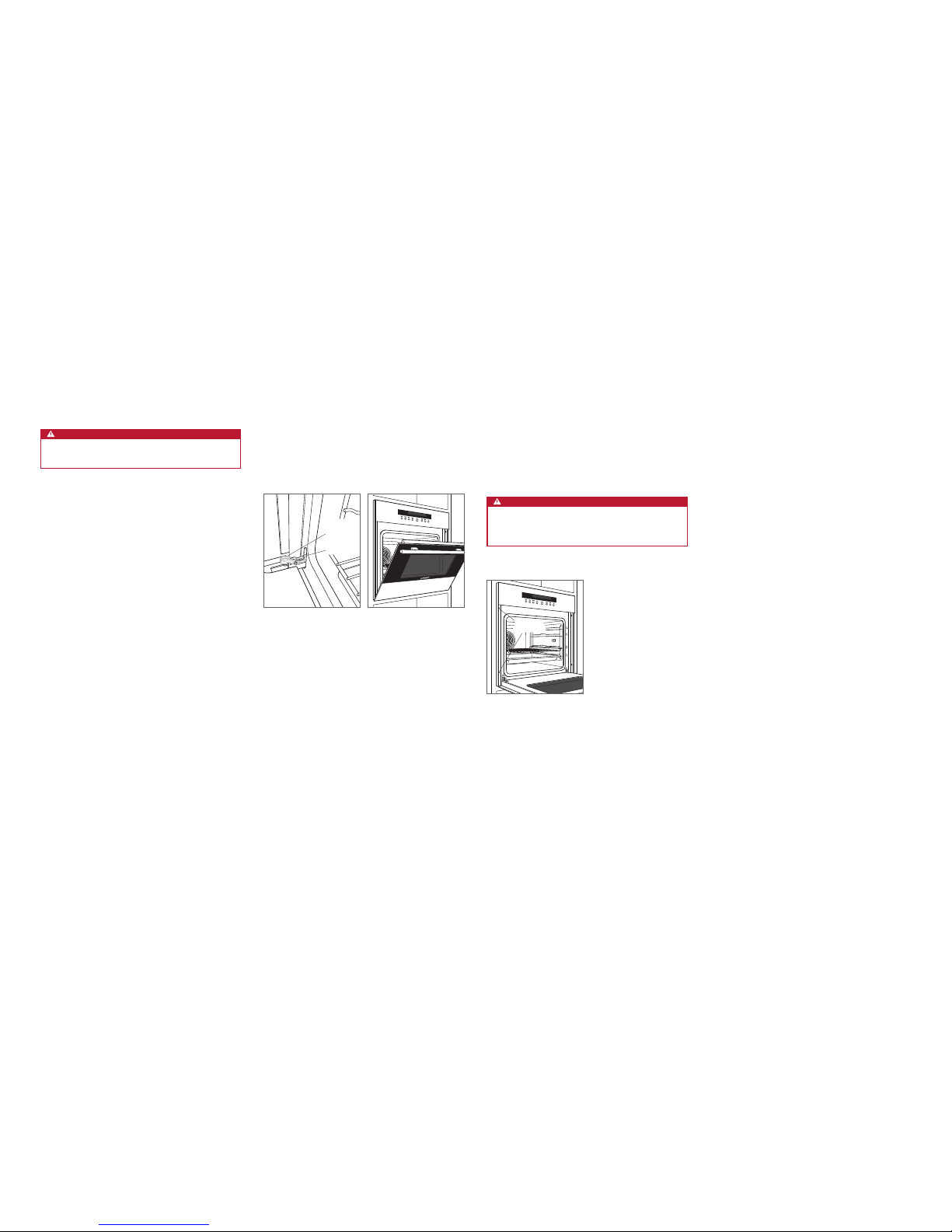
EXTRACCIÓN DE LA PUERTA DEL HORNO
Para extraerla, abra la puerta completamente. Gire los
pasadores de las bisagras hacia adelante hasta la posición
abierta. Cierre la puerta hasta aproximadamente 30º abierta
y, a continuación, tire hacia arriba y hacia fuera. Observe las
siguientes ilustraciones.
Para instalarla de nuevo, inserte las bisagras de la puerta en
las aperturas del marco. Abra la puerta del horno completamente y gire los pasadores de las bisagras hacia adelante
hasta la posición cerrada.
POSICIÓN
ABIERTA
POSICIÓN
CERRADA
Pasador de la bisagra de la
puerta del horno.
Puerta abierta 30°
Localización y solución de problemas
NOTA IMPORTANTE: si el horno no funciona correctamente,
siga estos pasos de localización y solución de problemas:
• Compruebe que el horno está conectada a la red
eléctrica.
• Compruebe que las conexiones eléctricas son correctas.
• Si el horno no funciona correctamente, póngase en con-
tacto con un servicio de asistencia técnica autorizado
de Wolf. No realice ninguna reparación en el horno. Wolf
no se responsabiliza de las tareas de mantenimiento
que deban realizarse para corregir una instalación
defectuosa.
Sub-Zero, Sub-Zero & Design, Sub-Zero & Snowake Design, Dual Refrigeration, The Living Kitchen, Great American Kitchens The Fine Art of Kitchen Design, Wolf, Wolf & Design, Wolf Gourmet, W & Design, los mandos de color rojo, Cove, and Cove & Design son marcas registradas y marcas de servicio de Sub-Zero Group, Inc. y sus liales.
Todas las demás marcas son propiedad de sus respectivos propietarios en los Estados Unidos y en otros países.
2 | Français
FOURS DE LA SÉRIE E 61 cm
Information concernant le produit
Les renseignements importants concernant le produit,
notamment la référence modèle et le numéro de série,
gurent sur la plaque des caractéristiques du produit. La
plaque des caractéristiques est située sur le côté gauche du
cadre de la face avant. Vous devez ouvrir la porte du four
pour voir la plaque des caractéristiques. Reportez-vous à
l‘illustration ci-après.
Si vous devez contacter le service après-vente, contactez
le prestataire agréé par l‘usine Wolf avec les numéros de
modèle et de série.
Table des matières
2 Fours de la Série E 61 cm
3 Spécications
5 Installation
5 Dépistage des pannes
Les caractéristiques et spécications peuvent être modiées
à tout moment sans préavis.
Remarque importante
Pour garantir une installation de ce produit aussi sûre et
efcace que possible, veuillez faire particulièrement attention aux mentions mises en évidence tout au long de ce
guide, notamment :
REMARQUE IMPORTANTE met l‘accent sur un renseigne-
ment particulièrement important.
MISE EN GARDE signale un danger qui pourrait causer une
blessure mineure ou endommager le produit si vous ne
suivez pas les instructions.
AVERTISSEMENT signale un danger qui pourrait causer
des blessures graves voire fatales si vous ne prenez pas
certaines précautions.
REMARQUE IMPORTANTE : Conservez ces instructions pour
l‘électricien local chargé des inspections.
Emplacement de la plaque des
caractéristiques.
PLAQUE DES
CARACTÉRISTIQUES
 Loading...