

Wolf ICBDF486C series, ICBDF366 series, ICBDF364C series, ICBDF364G series, ICBDF486G series Installation Instructions Manual
...
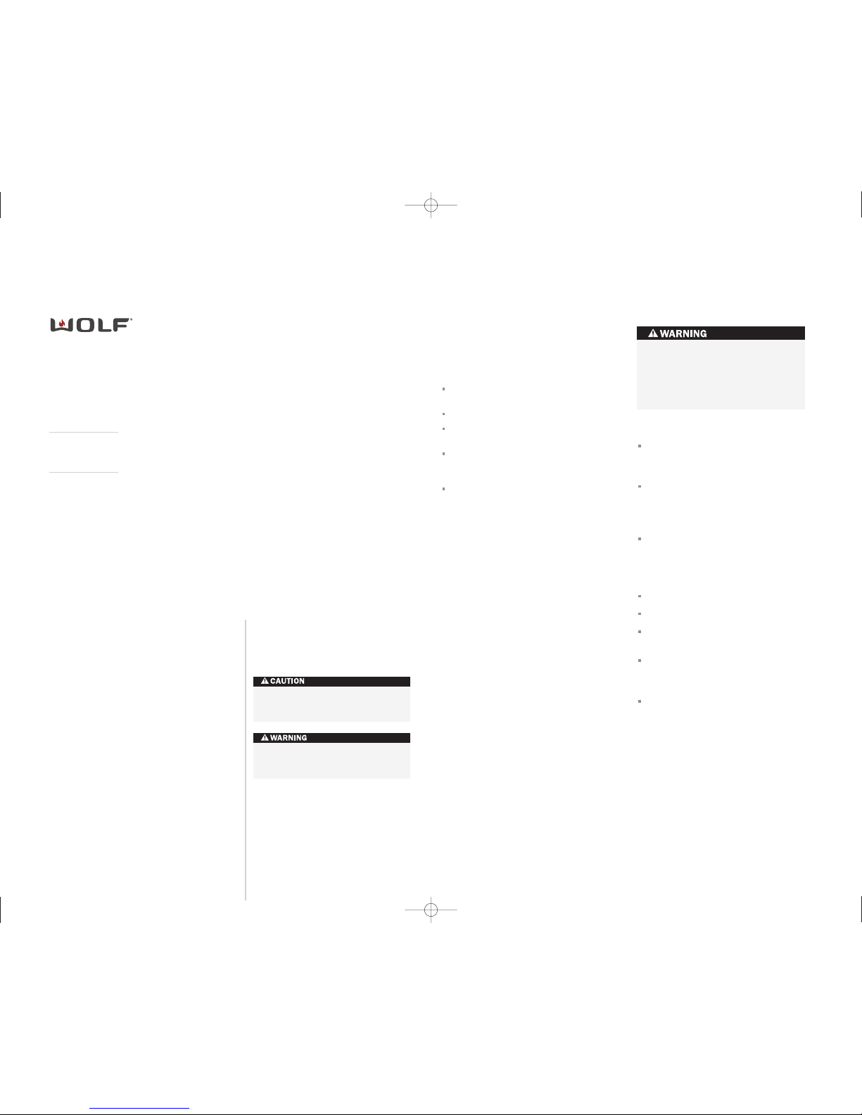
DUAL FUEL RANGES
INSTALLATION INSTR UCTION S
Natu ral ga s .
Le av e instructio ns w it h the owner.
This cookto p is a pprov ed for use with
Mo del Ser ies
ICBDF366
ICBDF304
ICBDF364C
ICBDF364G
ICBDF486C
ICBDF486G
ICBDF484CG
ICBDF484F
ICBDF606CG
ICBDF604CF
As you read this use & care information,
take particular note of the CAUTION and
WARNING symbo ls when they appear.
This information is important for safe and
efficient use of the Wolf equipment.
In addition, this use & care information may
signal an IMPORTANT NO TE which highlights
information that is especially important.
signals a s ituation wher e minor injury or
product damage may occur if you do not
follow instructions.
states a hazard that may cause serious
injury or death if precautions are not
followed.
WOLF®is a registered trademar k of Wolf Appliance, Inc.
I NS T A LL A TI O N R E QUIREMENTS
IMPORTANT NOTE: This installation must
be completed byaqualified installer,
service agency or gas supplier.
IMPORTANT NOTE:
Save these installation
instructions for the local inspector’s use.
Installation to be carried out only by an
authorised person.
Do not modify this appliance.
Please read the entire installation instructions prior to installation.
Installer:
please retain these instructio ns
for local inspector’s reference, then leave
them with the homeowner.
Homeowner:
please read and keep these
instructions for future reference and be sure
to read the entire use & care in
formation
prior to use.
IMPORTANT NOTE:
This appliance must be
installed in accordance with local codes. The
correct voltage, frequency and amperage must
be supplied to the appliance fromadedicated,
grounded circuit which is protected by a
properly sized circuit breaker or time delay
fuse. The proper voltage, frequenc y, and
amperage ratings are listed on the product
rating plate.
Record the model and serial nu mbers before
installing the dual fuel ran g e. Both numbers
are listed on the rating plate, loc ated rear of
removable lower panel.
W O L F DU A L F UEL RANGE S
IMPORTANT NOTE:
Installation and service must be
performed by a qualified installer,
service agency or the gas supplier.
Do not store or use gasoline or
other flammab le vapors and liquids
in the vicinity of this or any other
appliance.
A ventilation hood is recomme nded
for use with the Wolf dual fuel range.
WHAT TO DO IF YOU SMELL GAS:
Do not try to light any appliance.
Do not touch any electric al switch.
Do not use an y phone in your
building.
Immediately call your gas supplier
from a neighbor’s phone. Follow the
gas supplier’s instructions.
If you cannot reach your gas
supplier, call the fire depar
tment.
If the information in this book is
not followed exactly,afire or
explosion may result, causing
property damage, personal injury
or death.
R A T I N G PL A T E
I N FORM A T I O N
Model Number
Serial Number
CONT A C T
INFOR M A T I O N
Imported and
distributed by:
Multyflex
Website:
www.multyflex.com.au
IMPORTANT NOTE:
Statutory requirements: This
appliance shall be installed in
accordance with the manu facturer’s installation instructions,
local gas fitting regulations,
municipal building codes, electrical wiring regulations, and
AS/NZ5601 the Australian Standard
for gas installations. Refer also to
AS/NZ5601 for gas pipe sizing
tables.
Unsuitability for use in marine
craft, c aravans or mobile homes,
unless each burner is fitted with a
flame safeguard.

3
B EF O R E Y O U S T A R T
Proper installation i s your responsibility.
Installations must be performed by a
qualified or licensed contractor, plumber or
gas fitter, qualified or licensed by the state,
province or region w here th is appl iance is
being installed. You must also ensure that
electrical installatio n is a dequate and
conforms with all lo cal cod es and
ordinances.
Proper gas supply mu st be available; refer
to gas supply requir ements on page 9.
Electrical ground is requi
red; see electrical
requirements on page 10.
Check the location w here th e range will be
installed. The locati on shou ld be away from
strong draft areas, such as windows, doo r s
and strong heating v ents or fans. Do not
obstruct the flow of air. The area in which
you are installing t his app liance must have
an adequate supply o f fresh air to ensure
proper combustion and ventilation.
Make sure you have everything necessary
for proper installati o n. It is the responsibility of the i
nstaller to comply w ith the installation clearances spe cified on the product
rating plate. The ra ting pl ate is located rear
of removable lower p a nel.
All openings in the wall or floor where the
range is to be inst a lled m u st be sealed.
The cooking range to be installed only on
the floor.
When installing the range under existing
cabinets where the i nstallation does not
meet the minimum cab inet cl earances,
install a ventilation hood or other noncombustible surface a bove th
e range to
avoid burn hazards. Refer to minimum
clearances on page 3 .
V EN T I L AT IO N O P T I O N S
IMPORTANT NOTE:
A suitable ventilatio n
hood must be install ed. We recomm end a Wolf
Pro Ventilation Hood be installed with the Wolf
dual Fuel Range. Con tact yo ur Wolf deal e r for
details.
IMPORTANT NOTE:
When installing a ve n tilation hood, refer to the specific requirem ents
of the hood for the minimum dimension to
countertop.
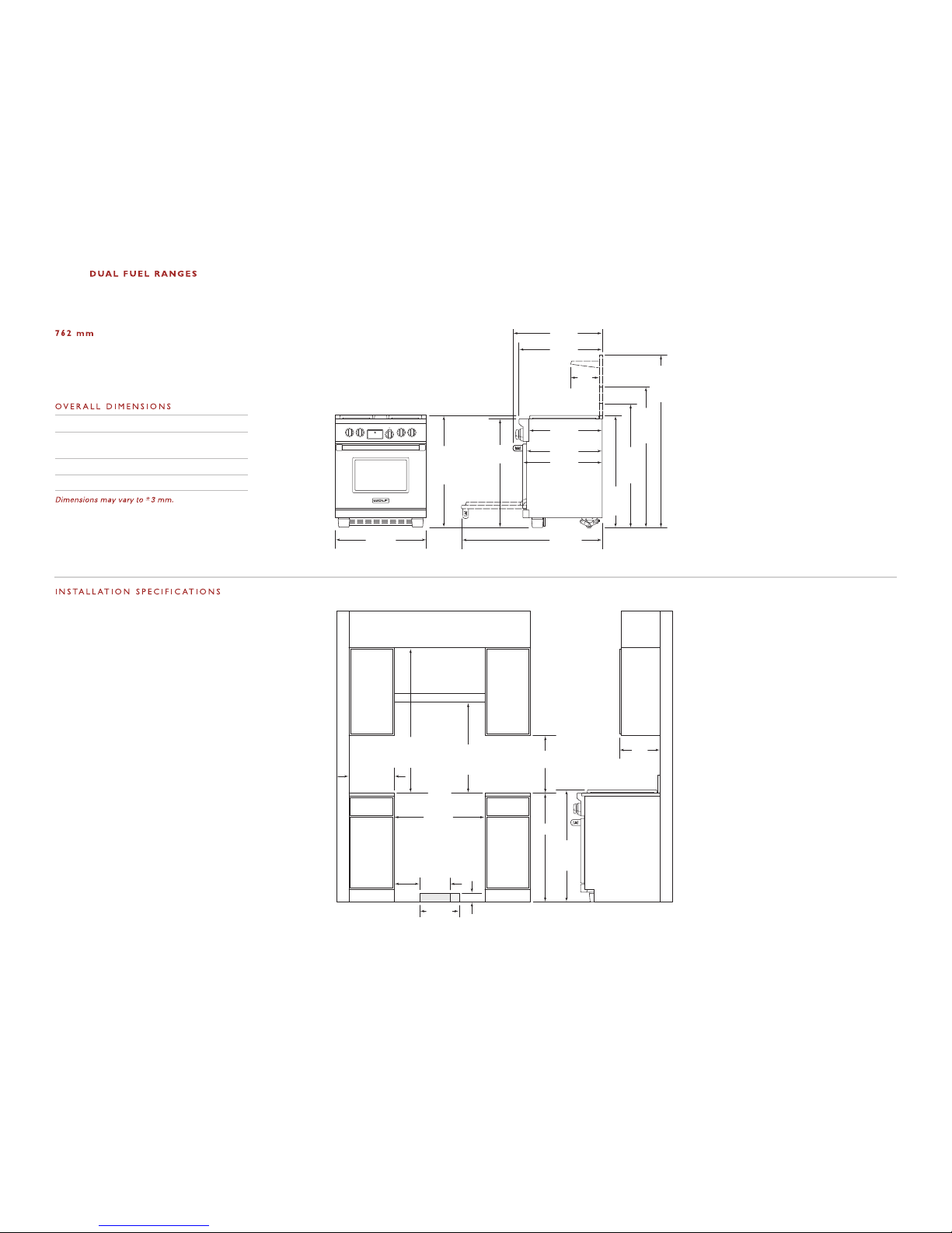
I NS TA L L AT I ON S P E C I F I C A T I O N S
Wolf dual fuel ranges come in 762 mm,
914 mm, 1219 mm and 1524 mm widths.
Illustrations on page s 4–
7 provide the overal l
dimensions and instal l ation specifications for
each width of dual fuel range.
Each range is design ed to fit between cabinets
set at the distance specified by the un it. For
example, a 914 mm r ange wi ll fit a 914 mm
opening. The exceptio n is t he 1524 mm unit
which will require a 1530 mm opening.
IMPORTANT NOTE:
Cabinet opening dimen sions shown in the installation specifica t ions
illustrations must be used. These dimensi ons
provide for required clearanc
es.
Each unit is designe d with a terminal block on
the rear of the ran g e. Hav e a qu alified electrician or installer wi re your unit from the elec t rical supply, through the knock out in the unit
base and to the ter minal b lock on the range.
IMPORTANT NOTE:
Locate the electrical
supply within dimensi ons sho wn in the
installation specifica tions i llustrations and
flush with back wall .
Refer to the install ation s pecifications illustration for your model on pages 4– 7 for the ex
act
rough opening dimensi ons and location of the
gas supply and elect rical.
Wolf dual fuel ranges usin g natur al gas will
operate up to an al t itude of 2438 m without
any adjustment. Natur a l gas and LP gas installations from 2438 m to 3353 m need the high
altitude conversion k it.
I NS TA L L AT I ON I N S T R U C T I O N S
I NS TA L L AT I ON S P E C I F I C A T I O N S
M I N I M U M C L E A R A N C E S
IMPORTANT NOTE:
Caution must be used in
planning the proper installation of the Wolf
dual fuel range to a void fi re or damag
e to
adjacent cabinetry or kitchen equipment.
Be sure to follow t he mini mum cle arances
established in the f inished rough opening
dimensions.
For installation against a rear combustible
surface a 254 mm classic stainless steel riser
must be used. Refer part number 8 04387.
Refer to the install ation s pecifications illustration for your model on pages 4– 7 for the exact
rough opening dimensio ns.
Maintain th e fol lowing clearances to
combustible materials:
Minimum 457 mm clear ance fr om bott om
of upper cabinet to countertop, within
152 mm minimum side clearance.
Minimum 762 mm clear ance b e tween c ountertop and bottom of wood or metal
cabinet, which is pr otected by not less than
6 mm flame retardant millboard covered
with not less than No. 28 MSG sheet st e el,
.4 mm stainless stee l, or .6 mm aluminum
or .5 mm copper.
Minimum 914 mm clear ance b e tween c ountertop and bottom of an unprotected wood
or metal cabinet.
Bottom of ventilation hood must be
600 mm minimum to 9 14 mm maximum
from countertop.
I S L A N D | P E N I N S U L A I N S T A L L A T I O N S
For island i n stallations,
the range should
not be installed wit hin an enclosure having an
adjacent rear wall l ess tha n 305 mm from the
rear of the unit th at rise s above the countertop.
For peninsula installati ons,
the range must
have a 152 mm minim u m clea rance t o the side
wall, left or right side, and 305 mm mi nimum
clearance to the rea r wall.
Refer to the install a tion s pecifications illustration for your model on pages 4– 7 for the exact
rou
gh opening dimensions .
Failure to locate the range wit h out t he
proper clearances will result in a fire
hazard.
4
W
ICBDF304
OLF
330 mm
LOCATION OF
ELECTRICAL
914 mm
937 mm
TO
COOKING
SURFACE
600 mm min
COUNTERTOP TO
COMBUSTIBLE
MATERIALS
VENTILATION HOOD
457 mm min
TO COUNTERTOP
LOCATION OF GAS AND
ELECTRICAL EXTENDS 57 mm
ON FLOOR FROM BACK WALL
762 mm
FINISHED ROUGH
OPENING WIDTH
83 mm
216
mm
254 mm
LOCATION
OF GAS
SUPPLY
600 mm min TO
914 mm max
TO BOTTOM OF
VENTILATION HOOD
ISLAND INSTALLATIONS: 305 mm MINIMUM
CLEARANCE FROM BACK OF RANGE TO
COMBUSTIBLE REAR WALL ABOVE COUNTERTOP–
0 mm TO NON-COMBUSTIBLE MATERIALS
330 mm
max
152 mm
min TO
COMBUSTIBLE
MATERIALS
(BOTH SIDES)
759 mm
OVERALL WIDTH
937
mm
ISLAND
TRIM
1165
mm
WITH
254 mm
RISER
1419
mm
WITH
508 mm
RISER
1038
mm
WITH
127 mm
RISER
1194 mm
664 mm
635 mm
613 mm
699 mm
235
mm
749 mm
OVERALL DEPTH
*937 mm MIN TO 991 mm MAX.
911
mm
937 mm
OVERALL
HEIGHT TO
COOKING
SURFACE*
Overall Width 759 mm
Overall Height
(to cooking surface) 937 mm
Overall Depth 749 mm
Opening Width 762 mm
DUAL FUEL RANGE
IMPORTANT NOTE: In non-island applications,
a minimum 127 mm riser is required for model
ICBDF304.
Note A:
Side clearances. If the distance
measured from the periphery of the
nearest burner to any vertical surface
is less than 200 mm, the surface shall
be protected in accordance with
AS/NZ5601.
Note B:
The rangehood fitted above the
cooktop must be installed according
to the installation instructions for
the rangehood. A minimum
distance of 750 mm is required for a
range hood and 750 mm for an
exhaust fan
.
5
I NS T A LL A TI O N I N S T R U C T I O N S
483 mm
LOCATIONOF
ELECTRICAL
914
mm
937 mm
TO
COOKING
SURFACE
VENTILATIONHOOD
457 mm min
TO COUNTERTOP
LOCATIONOF GAS AND
ELECTRICAL EXTENDS 76 mm
ON FLOOR FROM BACK WALL
914 mm
FINISHED ROUGH OPENING WIDTH
83 mm
216
mm
381 mm
LOCATION
OF GAS
SUPPLY
mm min TO
914 mm max
TO BOTTOMOF
VENTILATIONHOOD
600 mm min
COUNTERTOP
TO COMBUSTIBLE
MATERIALS
762 mm min
FOR CHARBROILER
ISLAND INSTALLATIONS: 305 mm MINIMUM
CLEARANCE FROM BACK OF RANGE TO
COMBUSTIBLE REAR WALL ABOVECOUNTERTOP–
330 mm
max
911 mm
OVERALLWIDTH
1194 mm
699 mm
235
mm
749 mm
OVERALL DEPTH
LEGS AND CASTERS ALLOW
54 mm HEIGHT ADJUSTMENT
911
mm
937 mm
OVERALL
HEIGHT TO
COOKING
SURFACE
616 mm
641 mm
1064
mm
WITH
127 mm
RISER
1191
mm
WITH
254 mm
RISER
1445
mm
WITH
254 mm
RISER
I N S T A L L A T I O N SPE C I F I C A T I O N S
O VERA L L D I M E N S I O N S
Overall Width 911 mm
Overall Height
(to cooking surface) 937 mm
Overall Depth 749 mm
Opening Width 914 mm
Dimensions may vary to±3 mm.
9 14 m m DU A L F U E L R A N G E S
M O D E L I C B D F 3 6 6
M O D E L I C B D F 3 6 4 C
M O D E L I C B D F 3 6 4 G
IMPORTANT NOTE: In non-island applications,
a mini mum 127 mm riser is required for model
ICBDF366 and minimum 254 mm ri ser required for
models ICBDF364C and ICBDF364G installed against
a combu stible surface. The island trim and 127 mm
riser may on ly be used against a non-combustible
surface for m odels ICBDF364C and ICBDF364 G .
NOTE
A
NOTE
B
Note A:
Side clearances. If the distance
measured from the periphery of the
nearest burner to any vertical surface
is less than 200 mm, the surface shall
be protected in accordance with
AS/NZ5601.
Note B:
The rangehood fitted above the
cooktop must be installed according
to the installation instructions for
the rangehood. A minimum
distance of 750 mm is required for a
range hood and 750 mm for an
exhaust fan
.
600
50 mm TO NON-COMBUSTIBLE MATERIALS
6
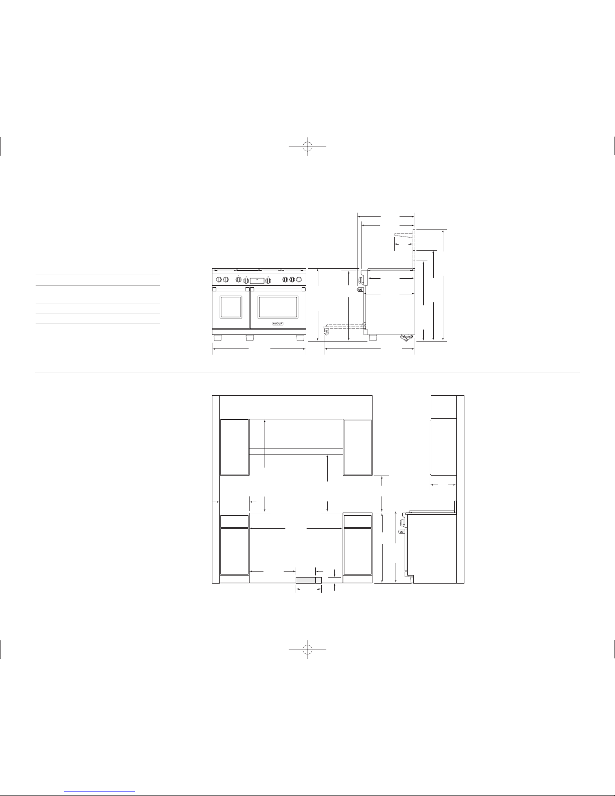
W O L F DU A L F UE L R A N GE S
330 mm
LOCATIONOF
ELECTRICAL
914
mm
937 mm
TO
COOKING
SURFACE
VENTILATIONHOOD
LOCATIONOF GAS AND
ELECTRICAL EXTENDS 76 mm
ON FLOOR FROM BACK WALL
ISLAND INSTALLATIONS: 305 mm MINIMUM
CLEARANCE FROM BACK OF RANGE TO
COMBUSTIBLE REAR WALL ABOVECOUNTERTOP–
1219 mm
FINISHED ROUGH OPENING WIDTH
610 mm
83 mm
254 mm
LOCATION
OF GAS
SUPPLY
457 mm min
TO COUNTERTOP
mm min TO
914 mm max
TO BOTTOMOF
VENTILATIONHOOD
600 mm min
COUNTERTOP
TO COMBUSTIBLE
MATERIALS
762 mm min
FOR CHARBROILER
330 mm
max
1216 mm
OVERALLWIDTH
1194 mm
699 mm
235
mm
749 mm
OVERALL DEPTH
LEGS AND CASTERS ALLOW
54 mm HEIGHT ADJUSTMENT
911
mm
937 mm
OVERALL
HEIGHT TO
COOKING
SURFACE
616 mm
641 mm
1064
mm
WITH
127 mm
RISER
1191
mm
WITH
254 mm
RISER
1445
mm
WITH
254 mm
RISER
I N S T A L L A T I O N S P E C I F I C A T I O N S
O V E R A L L D I M E N S I O N S
Overall Width 1216 mm
Overall Height
(to cooking surface) 937 m m
Overall Depth 749 mm
Opening Width 1219 mm
Dimensions may vary to±3 mm.
1 21 9 m m D U A L F U E L R A N G E S
GC8 44FDBCI
I C B D F 4 8 4 F
C8 64FDBCI
I C B D F 4 8 6 G
IMPORTANT NOTE: In non-island applications, a
minimum 254 mm ris er is required for all 1219 mm
models installed against a combustible surface.
The is land trim and 127 mm riser may only be used
against a no n -combustible surf ace.
NOTE
B
Note A:
Side clearances. If the distance
measured from the periphery of the
nearest burner to any vertical surface
is less than 200 mm, the surface shall
be protected in accordance with
AS/NZ5601.
Note B:
The rangehood fitted above the
cooktop must be installed according
to the installation instructions for
the rangehood. A minimum
distance of 750 mm is required for a
range hood and
750 mm for an
exhaust fan
.
NOTE
A
600
50 mm TO NON-COMBUSTIBLE MATERIALS
 Loading...