

Wolf ICBDD, CTWH30, CTWH36, IH4227, CTEWH30I Installation And Operation Manual
...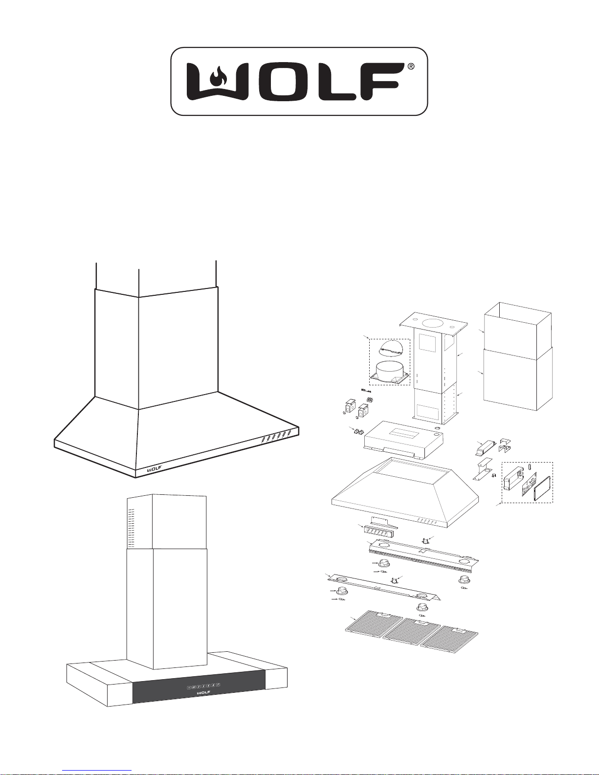
CT & CTE HOODS
DD & ICBDD VENTILATION
(Including Parts Lists and Exploded Views)
1
10
15
9
14
8
13
5
R
E
T
L
I
H
F
G
I
M
H
U
I
D
E
M
W
O
L
Y
A
L
E
T
D
H
G
I
2
12
L
6
3
11
4
6
3
4
WOLF APPLIANCE, INC 2009 ALL RIGHTS RESERVED JOB AID 810125 REVISION C JAN. 2009
7


General Information CT Hoods and DD Ventilation
SECTION 1
GENERAL INFORMATION
1-1
General InformationCT Hoods and DD Ventilation
INTRODUCTION
This Wolf Cooktop and Downdraft Ventilation Technical Service Manual, has been compiled with information provided
by Broan-Nu Tone LLC. This manual provides the most recent technical service information that will enable the
service technician to troubleshoot and diagnose malfunctions, perform necessary repairs and return a Wolf Ventilation
product to proper operational condition.
The service technician should read the complete instructions contained in this Service Manual before initiating any
repairs on a Wolf Appliance.
IMPORTANT SAFETY INFORMATION
Below are the Product Safety Labels used in this manual.
The “Signal Words” used are WARNING & CAUTION.
Please note that these safety labels are placed in areas
where awareness of personal safety and product safety
should be taken and lists the precautions to be taken when
the signal word is observed.
INDICATES THAT HAZARDOUS OR UNSAFE
PRACTICES COULD RESULT IN SEVERE
PERSONAL INJURY OR DEATH
Indicates that hazardous or unsafe practices
could result in minor personal injury or product
and/or property damage
In addition, please pay attention to the signal
word “NOTE”, which highlights especially
important information within each section.
TECHNICAL ASSISTANCE
If you should have any questions regarding a Wolf
appliance and/or this manual, please contact:
Wolf Appliance, Inc.
ATTN.: Service Department
P.O. Box 44988
Madison, WI 53744-4988
Customer Service
Phone #: (800) 332 - 9513
T echnical Assistance
Phone #: (800) 919 - 8324
Parts / Warranty Claims
Phone #: (800) 332 - 9513
Customer Service E-mail Address
customerservice@wolfappliance.com
Customer Service & Technical Assistance
Facsimile #: (608) 441 - 5887
Parts / Warranty Claims
Facsimile #: (608) 441 - 5886
This manual is designed to be used by Authorized Service Personnel only. Wolf Appliance, Inc. assumes no
responsibility for any repairs made to Wolf appliances by anyone other than Authorized Service Technicians.
The information and images contained in this manual are the copyright property of Wolf Appliance, Inc., an affi liate of Sub-Zero,
Inc. Neither this manual nor any information or images contained herein may be copied or used in whole or in part without the
express written permission of Wolf Appliance, Inc., an affi liate of Sub-Zero, Inc. © Wolf Appliance, Inc., all rights reserved.
Offi ce Hours:
7:00 AM to 7:00 PM Central Standard Time
Monday through Friday
1-2

General Information CT Hoods and DD Ventilation
TABLE OF CONTENTS
Page #
Section 1 - General Information ...................... 1-1
Introduction ........................................................ 1-2
Important Safety Information ............................. 1-2
T echnical Assistance ......................................... 1-2
Table of Contents ............................................... 1-3
Warranty Information ......................................... 1-4
Model Descriptions ............................................ 1-5
Section 2 - Installation Information ............... 2-1
CT & Island Hood Overall Dimensions .............. 2-2
CTEWH Overall Dimensions ............................. 2-3
CTEIH Overall Dimensions ................................ 2-4
CT Hood Placement ........................................... 2-5
CT Wall Hood Installation Considerations ......... 2-6
CT Wall Hood Installation .................................. 2-7
Ductwork Installation ......................................... 2-8
Island Hood Installation Considerations ............ 2-9
Island Hood Installation ..................................... 2-10
Hood Internal Blower Installation ...................... 2-12
CTE Hood Installation Considerations .............. 2-13
CTEW Hood Installation Specifi cations ............ 2-14
CTEW Hood Electrical Requirements ............... 2-15
CTEW Hood Installation .................................... 2-15
CTEI Hood Installation Specifi cations ............ 2-17
CTEI Hood Electrical Requirements ............... 2-18
CTEI Hood Installation .................................... 2-18
Hood Remote Blower Installation ....................... 2-20
Downdraft Dimensions ...................................... 2-21
Downdraft Installation Specifi cations ................ 2-22
Downdraft Installation Requirements ................ 2-23
Downdraft Ducting Considerations ................... 2-24
Downdraft Blower Discharge ............................ 2-25
Downdraft Installation ....................................... 2-25
DD Internal Blower Installation .......................... 2-26
DD Remote Blower Installation ......................... 2-26
Section 3 - Controls & Operation ................... 3-1
Electronic Control for CT Wall Hoods ............... 3-2
Heat Sentry Mode ............................................. 3-2
Electronic Control for Downdraft ....................... 3-3
Cleaning ............................................................ 3-3
Electronic Control for Low Profi le Hoods .......... 3-4
Section 4 - Access and Removal ................... 4-1
CT Hoods:
Filter Removal ................................................... 4-2
Bulb and Light Assembly ................................... 4-3
Heat Sentry ....................................................... 4-4
Control Interface ................................................ 4-4
Power Outlet ...................................................... 4-5
Transformer ........................................................ 4-6
Fuse ................................................................... 4-6
Page #
Section 4 - Access and Removal (continued)
CTE Hoods:
Bulb Removal .......................................................... 4-7
Filter Removal ......................................................... 4-7
Inside Panel ............................................................. 4-7
Lamp Socket ............................................................ 4-8
Control Panel Removal ............................................ 4-8
Internal Blower Removal .......................................... 4-9
Control Board Removal ............................................ 4-10
Downdrafts:
Filter Removal .......................................................... 4-11
Internal Blower Removal .......................................... 4-12
Cam Switch Removal ............................................... 4-13
Front Air Box Removal ............................................. 4-13
Gear Motor Removal ................................................ 4-14
Power Control Board Removal ................................. 4-15
Section 5 - Troubleshooting .................................. 5-1
Ventilation Troubleshooting Chart ............................ 5-3
Downdraft Troubleshooting Chart ............................ 5-4
Low Profi le Troubleshooting Chart ........................... 5-5
Downdraft Cam Switch Operation ............................ 5-6
Downdraft Seal Damage Flow Chart ........................ 5-7
Section 6 - Technical Data ..................................... 6-1
Voltage and Temperature Parameters (CT & DD) .... 6-2
Voltage Parameters (CTE) ........................................ 6-3
Section 7 - Wiring Diagram ................................... 7-1
CTWH30 Wiring Diagram ........................................ 7-2
CTWH36 Wiring Diagram ....,................................... 7-3
IH4227 Wiring Diagram ........................................... 7-4
Low Profi le Hood Wiring Diagram ............................ 7-5
Downdraft Schematic .............................................. 7-6
Downdraft Wiring Diagram ...................................... 7-7
ICBDD Schematic .................................................... 7-8
ICBDD Wiring ........................................................... 7-9
Downdraft Control Schematic .................................. 7-10
Downdraft Power Supply Wiring .............................. 7-11
CT & IH Hood Power Supply Wiring ........................ 7-12
Blower Wiring ........................................................... 7-13
Section 8 - Parts List and Exploded Views ......... 8-1
CT Hood Parts List .................................................. 8-2
CT Hood Exploded View ......................................... 8-3
IH4227 Parts List ..................................................... 8-4
IH4227 Exploded View ............................................ 8-5
CTEWH30I, 36I, 45I Parts List ................................ 8-6
CTEWH30I, 36I, 45I Exploded View ....................... 8-7
CTEWH36, 45 Parts List ......................................... 8-8
CTEWH36, 45 Exploded View ................................ 8-9
CTEIH42 Parts List ................................................. 8-10
CTEIH42 Exploded View ........................................ 8-11
Downdraft Parts List ................................................ 8-12
Downdraft Exploded View ........................................ 8-13
ICBDD Parts List ...................................................... 8-14
ICBDD Exploded View ............................................. 8-15
1-3
WARRANTY INFORMATION
This page contains a summary of the Warranty supplied
with every Domestic Wolf ventilation product, followed by
details about the warranty.
NOTE: “ICB” warranties vary by Country and Distributor.
Contact selling Distributor for warranty coverage.
2 & 5 Y
EAR WARRANTY SUMMARY
2 YEAR TOTAL PRODUCT WARRANTY, • Parts and Labor.
3-5 • LIMITED *PARTS ONLY WARRANTY (Including Blower
motors).
General InformationCT Hoods and DD Ventilation
DETAILS:
Warranty applies to products installed in United States •
or Canada, for residential use only.
Warranty begins at time of unit’s initial installation.•
This Warranty does not cover Wolf Appliances installed •
in a demonstration kitchen, test kitchen, culinary school
kitchen, or similar installations. (See Special Warranty
below)
Warranty and Service information collected by Wolf •
Appliance, Inc. is arranged and stored under unit serial
number and/or customer’s name. Please note that Wolf
Appliance, Inc requests that you have model and serial
number available whenever contacting factory or parts
distributor.
SPECIAL WARRANTY SUMMARY
2 YEAR TOTAL PRODUCT WARRANTY, • Part and Labor.
DETAILS:
This Warranty applies to products installed in United •
States or Canada, for use in a demonstration kitchen,
test kitchen, culinary school kitchen, and similar installations that will help promote Wolf Appliance brand and
its products.
Warranty begins at time of unit’s initial installation.•
Warranty and Service information collected by Wolf •
Appliance, Inc. is arranged and stored under unit serial
number and/or customer’s name. Please note that
Wolf Appliance, Inc. requests that you have model and
serial number available whenever contacting factory or
parts distributor.
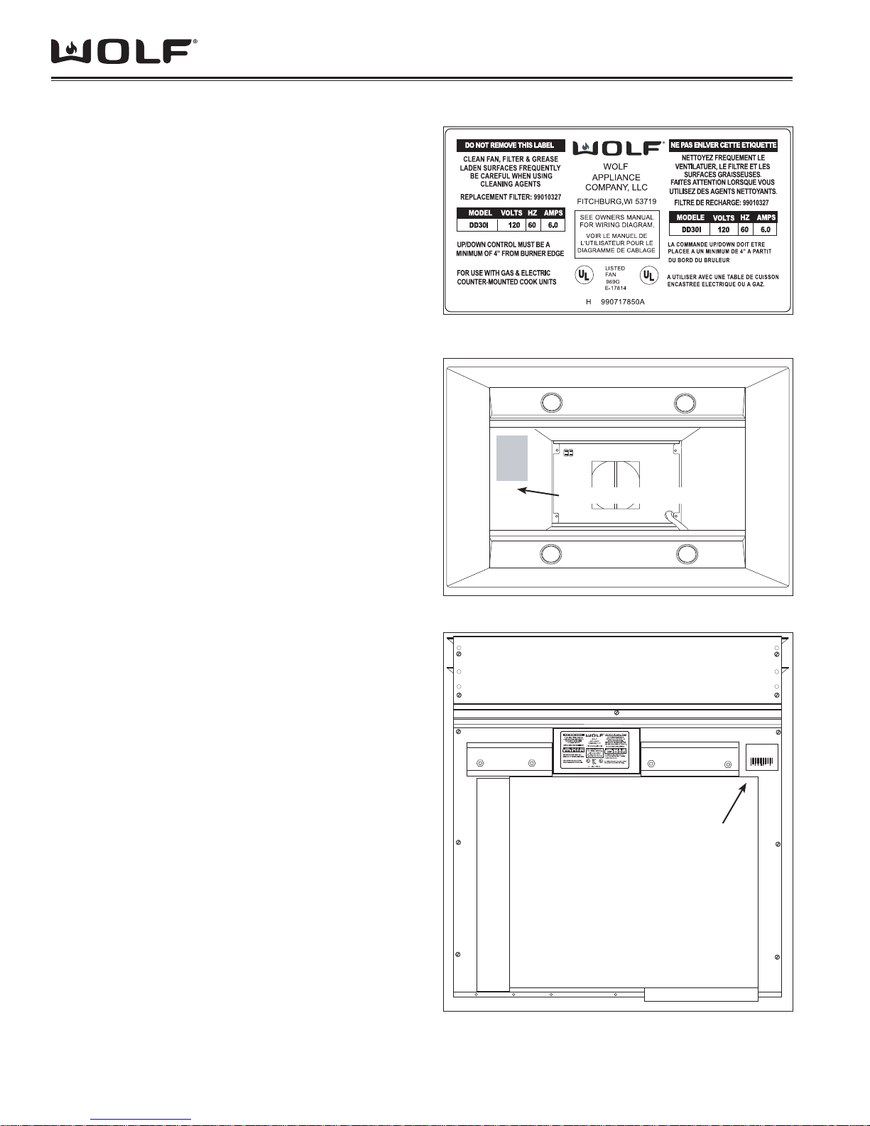
Figure 1-1 Serial Plate Layout
Unit Serial Number
Figure 1-2 Serial Plate Location (CT Hoods)
xxxxxxxxxxx
Unit Serial Number
INFORMATION PLATE AND SERIAL NUMBER
See Figure 1-1 for typical Information Plate layout. •
See Figures 1-2 & 1-3 for Serial Number location. •
Figure 1-3 Serial Plate Location (DD Ventilation)
1-4

General Information CT Hoods and DD Ventilation
MODEL DESCRIPTIONS
This section explains the model numbering system for the CT Hoods and Downdraft models covered in this manual.
EXAMPLE MODEL # ICB CTWH 30 I
INTERNATIONAL
PRODUCT TYPE
SIZE
BLOWER
PRODUCT TYPE
CTWH COOKTOP (OR CHIMNEY) WALL HOOD
CTEWH COOKTOP (OR CHIMNEY) LOW PROFILE WALL HOOD
CTEIH COOKTOP (OR CHIMNEY) LOW PROFILE ISLAND HOOD
IH ISLAND HOOD
DD DOWN DRAFT
SIZE
30 30 INCH WIDE UNIT
36 36 INCH WIDE UNIT
42 42 INCH WIDE X 27 INCH DEEP
(ONLY ON ISLAND HOOD)
45 45 INCH WIDE UNIT
(ONLY ON DOWN DRAFT)
BLOWER TYPE
I INTERNAL BLOWER
R REMOTE BLOWER
1-5

NOTES
General InformationCT Hoods and DD Ventilation
1-6

Installation Information CT Hoods and DD Ventilation
SECTION 2
INSTALLATION
INFORMATION
2-1
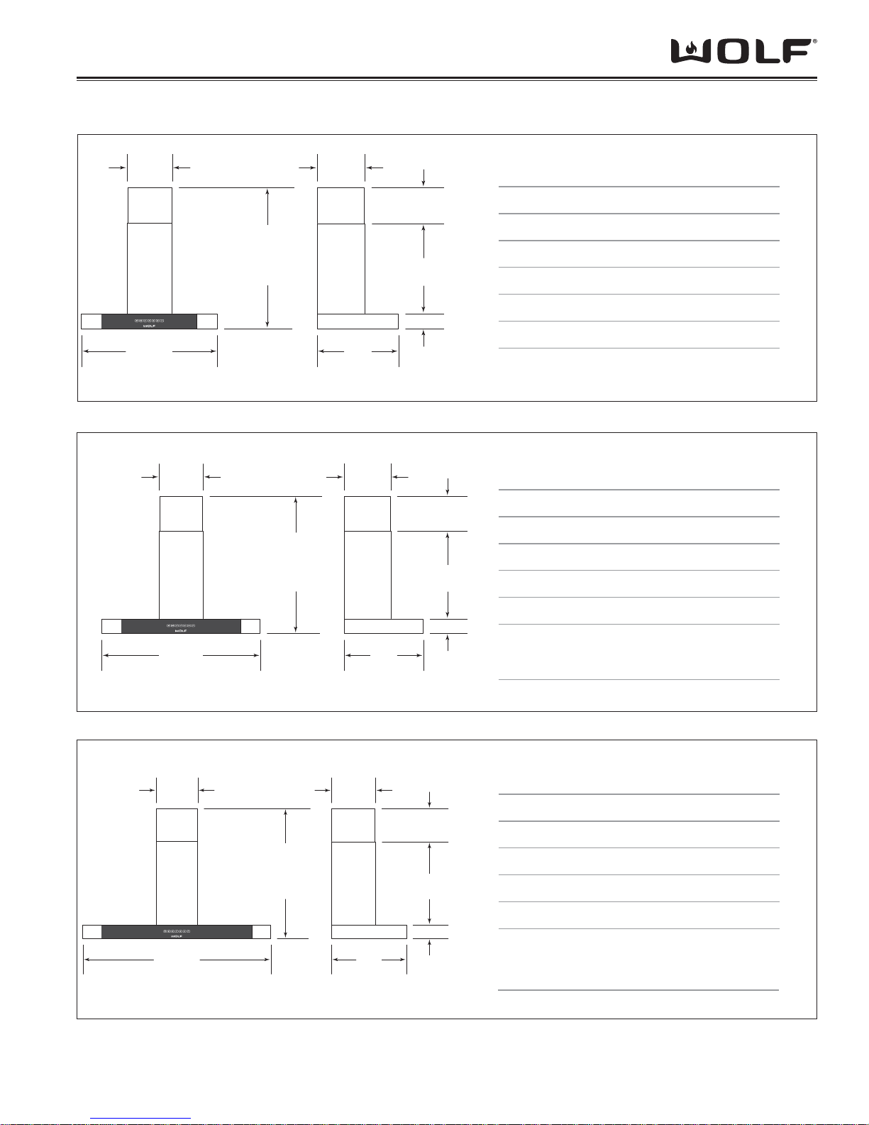
CT & ISLAND HOOD OVER-ALL DIMENSIONS
Installation InformationCT Hoods and DD Ventilation
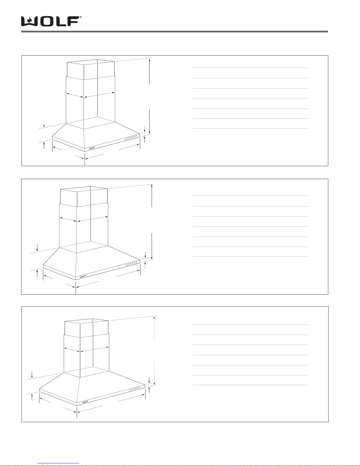
MODEL CTWH30
)267("03htdiW llarevO
(175mm)
91/4"
(235 mm)
67/8"
(533mm)
(305 mm)
21"
(533 mm)
(305mm)
21"
12"
12"
(457mm)
18"
(457 mm)
357/16"
(900 mm)
18"
30"
(762mm)
301/2"min
(775mm)
TO
481/2"max
(1232mm)
Overall Height (excluding chimney)
Overall Height (including chimney)
Max Height (full extension) 481/2" (1232)
Shipping Weight (shell only) 85 lbs (39 kg)
Dimensions may vary to
9
1
/16 " (40)
Figure 2-1 CTWH30 Dimensions
MODEL CTWH36
3211/16"min
(829 mm)
TO
507/8"max
(1292 mm)
9
1
/16 " (40)
Overall Height (excluding chimney) 91/4"(235)
Overall Height (including chimney) 3211/16"(830)
Max Height (full extension) 50
Shipping Weight (shell only) 100 lbs (45 kg)
Dimensions may vary to
1
+
/8"(3).
–
1
+
/8"(3).
–
67/8" (175)
301/2" (775)
7
53htdiW llarevO
/16" (900)
7
/8" (1292)
)335( "12htpeD llarevO
)335( "12htpeD llarevO
18"
(457 mm)
42"
(1067 mm)
91/4"
(235 mm)
27"
(686 mm)
12"
(305 mm)
Figure 2-2 CTWH36 Dimensions
MODEL IH4227
339/16"min
(851 mm)
TO
471/16"max
(1197 mm)
Overall Height (excluding chimney)
Overall Height (including chimney)
Max Height (full extension) 471/16" (1195)
Overall Depth 27" (686)
Shipping Weight (shell only) 110 lbs (50 kg)
9
1
/16 " (40)
Dimensions may vary to
Figure 2-3 IH4227 Dimensions
2-2
1
+
/8"(3).
–
)7601("24htdiW llarevO
91/4"(235)
339/16"(853)
Installation Information CT Hoods and DD Ventilation
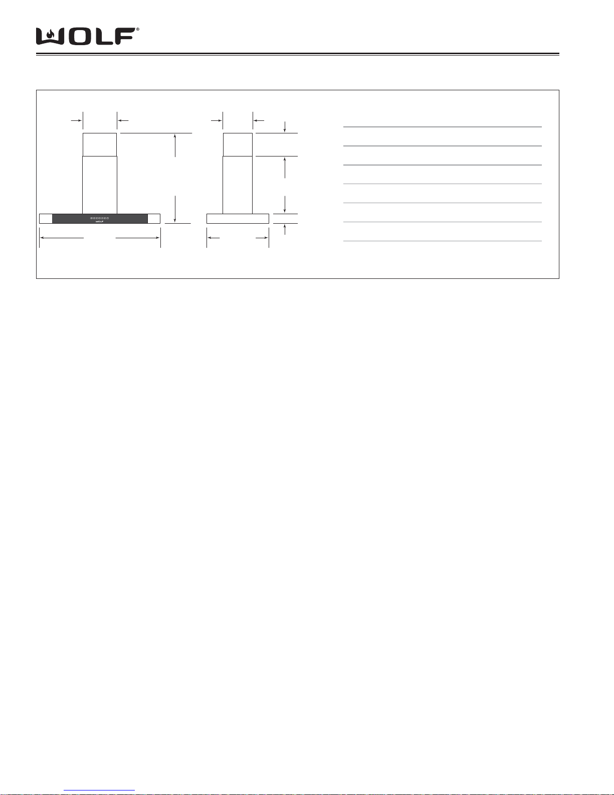
CTEW HOOD OVER-ALL DIMENSIONS
`
97/8"
(251)
30" (762)
OVERALL WIDTH
97/8"
(251)
29 1/8” (740)
TO
41 1/2” (1054)
OVERALL
HEIGHT
29 1/8” (740)
41 1/2” (1054)
OVERALL
TO
HEIGHT
107/8"
(276)
5 7/8” (149)
TO
18 3/8” (467)
MODEL CTEWH30I
Overall Width
Height (excluding chimney)
Min Height (including chimney)
201/8"
(511)
Max Height (full extension)
Overall Depth
173/4"
(451)
OVERALL DEPTH
31/8" (79)
Shipping Weight
Figure 2-4 CTEWH30 Dimensions
107/8"
(276)
5 7/8” (149)
TO
18 3/8” (467)
201/8"
(511)
MODEL CTEWH36(I)
Overall Width
Height (excluding chimney)
Min Height (including chimney)
Max Height (full extension)
30” (762)
3 1/8” (79)
29 1/8”(740)
41 1/2”(1054)
17 3/4”(451)
53 lbs (24kg)
36” (914)
3 1/8” (79)
29 1/8”(740)
41 1/2”(1054)
36" (914)
OVERALL WIDTH
97/8"
(251)
45" (1143)
OVERALL WIDTH
29 1/8” (740)
TO
41 1/2” (1054)
OVERALL
HEIGHT
Overall Depth
173/4"
(451)
OVERALL DEPTH
31/8" (79)
Shipping Weight
Figure 2-5 CTEWH36 Dimensions
107/8"
(276)
173/4"
(451)
OVERALL DEPTH
5 7/8” (149)
TO
18 3/8” (467)
201/8"
(511)
31/8" (79)
MODEL CTEWH45(I)
Overall Width
Height (excluding chimney)
Min Height (including chimney)
Max Height (full extension)
Overall Depth
Shipping Weight
CTEWH36
CTEWH36(I)
CTEWH45
CTEWH45I
17 3/4” (451)
51 lbs (23 kg)
57 lbs (26 kg)
45” (1143)
3 1/8” (79)
29 1/8” (740)
41 1/2” (1054)
17 3/4” (451)
55 lbs (25 kg)
63 lbs (29 kg)
Figure 2-6 CTEWH45 Dimensions
2-3
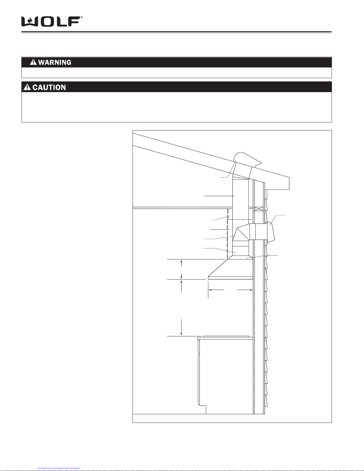
CTEI HOOD OVER-ALL DIMENSIONS
Installation InformationCT Hoods and DD Ventilation
12 1/8”
(308)
42" (1067)
OVERALL WIDTH
28 1/4” (718)
TO
41 1/2” (1054)
OVERALL
HEIGHT
10 7/8”
(276)
215/8" (549)
OVERALL DEPTH
2 1/8” (54)
TO
15 1/2” (394)
22 7/8”
(581)
31/8" (79)
MODEL CTEIH42
Overall Width
Height (excluding chimney)
Min Height (including chimney)
Max Height (full extension)
Overall Depth
Shipping Weight
Figure 2-7 CTEIH42 Dimensions
42” (1067)
3 1/8” (79)
28 1/4” (718)
41 1/2” (1054)
21 5/8” (549)
92 lbs (42 kg)
2-4

Installation Information CT Hoods and DD Ventilation
HOOD PLACEMENT
Flue Extension
Model Minimum Maximum
CTWH30
CTWH36
IH4227
301/2" (775) 481/2" (1232)
3211/16" (830) 507/8" (1292)
339/16" (853) 471/16" (1195)
D
EXTENSION
MINIMUM
FLUE
D
EXTENSION
MINIMUM
FLUE
CTEWH30I
CTEWH36(I)
CTEWH45(I)
CTEIH42I
29 1/8” (740)
29 1/8” (740)
29 1/8” (740)
28 1/4” (718)
41 1/2” (1054)
41 1/2” (1054)
41 1/2” (1054)
41 1/2” (1054)
A C
Figure 2-8 Hood Placement Dimensions
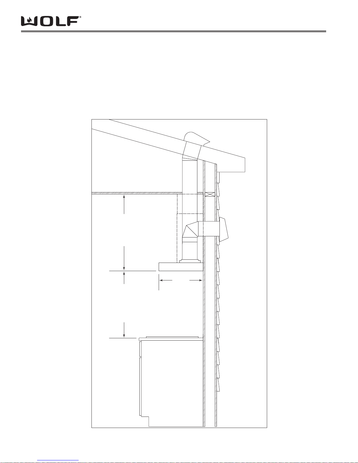
HOOD PLACEMENT
Wolf cooktop wall and island hoods come with a
telescopic chimney fl ue that allows you to reach ceiling
heights of 8’ (2.4m) to 9’ (2.7m) with a fi nished look.
A fl ue extension to accommodate 10’ (3m) ceilings is
available as a sales accessory for cooktop chimney
hoods only.
Installation of the cooktop wall or island hood should be
24” (610) to 30” 762) from the bottom of the hood to the
countertop.
To determine placement of the wall or island hood, you
must calculate the heights of the telescopic chimney
fl ue. Refer to the chart in Figure 2-8 above for the
minimum and maximum fl ue extension for specifi c
hood.
NOTE: Both sections of the telescopic chimney fl ue
must be installed in order for the chimney to be lifted
for service.
NOTE: If the height of the upper fl ue section is less
than 1/2” (13), you will need to modify the fl ue to affi x
to the fl ue attachment brackets.
A C
B
B
sdooH eliforP-woL potkooCsdooH yenmihC potkooC
CALCULATING CHIMNEY FLUE HEIGHT
Measure A (total kitchen height from fi nished fl oor to 1.
fi nished ceiling height).
Measure B (height from fi nished fl oor to countertop). 2.
Determine the desired distance from counter-top to 3.
bottom of hood (C). This dimension must be between
24” (610) and 30” (762).
NOTE: 8’ (2.4m) ceilings may not permit installation of the
wall or island hood at 30” (762) above the countertop.
To calculate the chimney fl ue height (D): D = A – (B 4.
+ C). This dimension must be between the minimum
and maximum fl ue extension for your specifi c hood as
shown in the chart.
2-5
Installation InformationCT Hoods and DD Ventilation
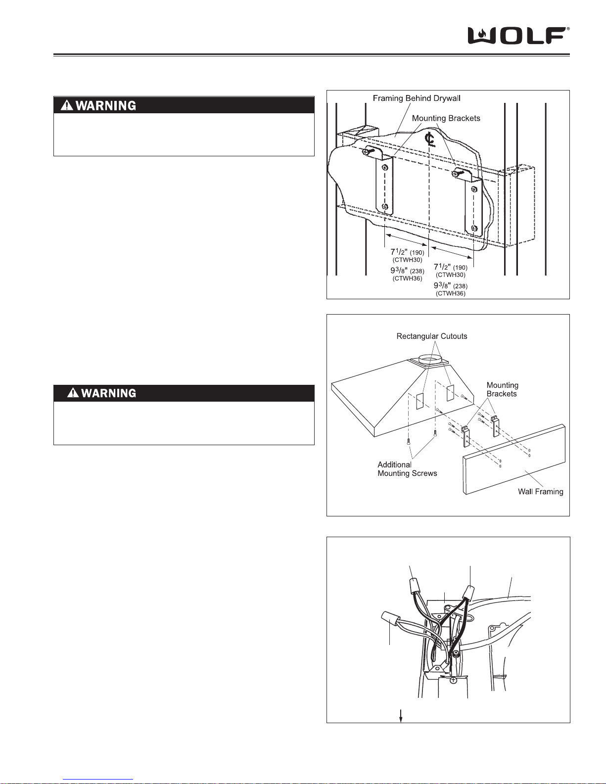
CT WALL HOOD INSTALLATION CONSIDERATIONS
TO REDUCE THE RISK OF FIRE, USE ONLY RIGID METAL DUCTWORK.
TO REDUCE THE RISK OF FIRE AND ELECTRIC SHOCK, THIS VENTILATION HOOD SHOULD ONLY BE
INSTALLED WITH BLOWERS MANUFACTURED BY WOLF APPLIANCE INC. AND SPECIFIED FOR USE WITH
THESE VENTILATION MODELS.
COUNTERTOP WALL HOODS INSTALLATION
SPECIFICATIONS AND PREPARATIONS FOR
MODELS CTWH30 & CTWH36
A straight, short duct run will allow 1.
the hood to perform more effi ciently.
Limit the number of elbows and transitions to as few as possible. Long
duct runs, elbows and transitions will
reduce the performance of the hood.
NOTE: All hoods must exhaust to the
outdoors.
NOTE: There is a possibility of noise issues, if a short duct run is coupled with a
remote blower.
Always use metal ducting. Do not 2.
use fl ex ducting.
Wolf recommends installing a back-3.
draft damper in all installations
(included with hood). In cold weather
installations a back-draft damper is
necessary to minimize the back-fl ow
of cold air into the room.
Wolf recommends the hood be in-4.
stalled 24” (610 mm) to 30” (762 mm)
above the cooking surface.
NOTE: Local building codes may require
the use of make-up air. Consult a local
HVAC professional for specifi c require-
ments.
ELECTRICAL REQUIREMENTS
Wolf cooktop wall hoods require a
separate, grounded, 110/120 VAC, 60 Hz
power supply. The service should have its
own 15 amp circuit breaker.
NOTE: You must follow all National
Electrical Code regulations. In addition,
be aware of local codes and ordinances
when installing your service.
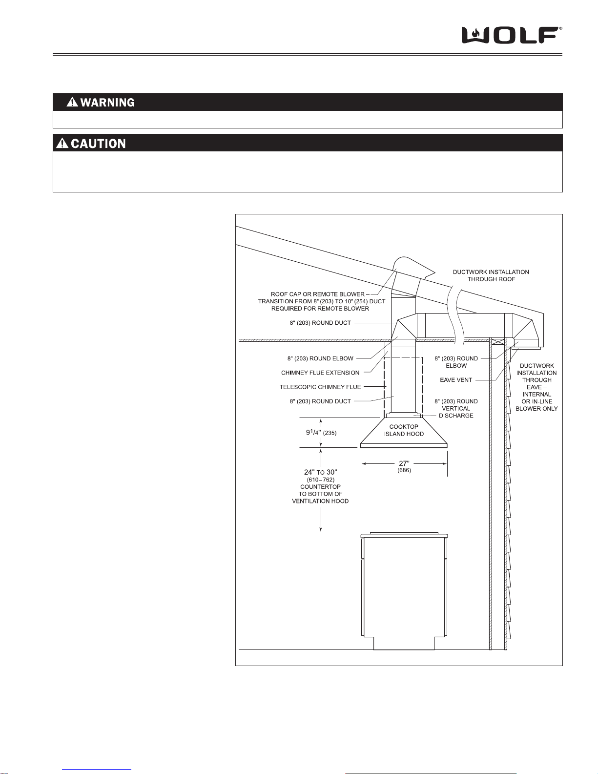
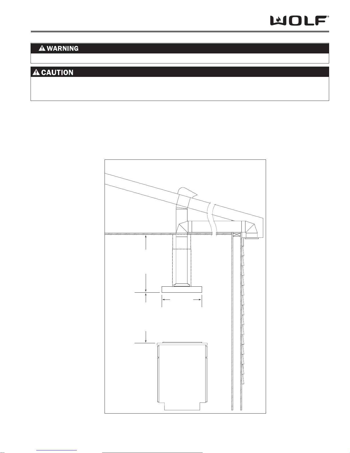
ROOF CAP OR REMOTE BLOWER –
TRANSITION FROM 8" (203) TO 10" (254) DUCT
REQUIRED FOR REMOTE BLOWER
8" (203) ROUND DUCT
CHIMNEY FLUE EXTENSION
TELESCOPIC CHIMNEY FLUE
8" (203) ROUND ELBOW
8" (203) ROUND DUCT
67/8" (175) OR 91/4" (235)
24" TO 30"
(610–762)
COUNTERTOP
TO BOTTOM OF
VENTILATION HOOD
Figure 2-9 CT Wall Hood Installation Considerations
COOKTOP
WALL HOOD
21"
(535)
DUCTWORK INSTALLATION
THROUGH ROOF
WALL CAP
OR REMOTE BLOWER
DUCTWORK INSTALLATION
THROUGH WALL
8" (203) ROUND
VERTICAL DISCHARGE
2-6
Installation Information CT Hoods and DD Ventilation
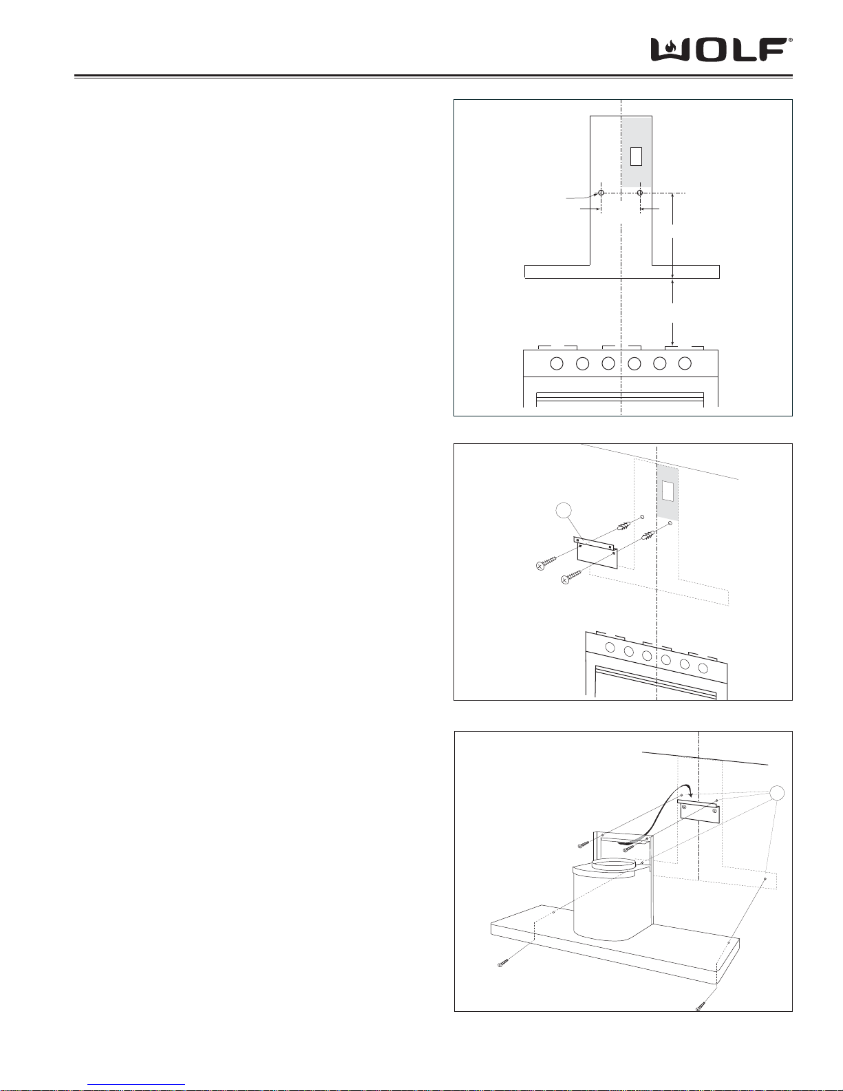
CT WALL HOOD INSTALLATION
DUE TO THE WEIGHT OF SOME HOODS, SEVERAL
PEOPLE MAN BE REQUIRED FOR A SAFE AND
PROPER INSTALLATION.
INSTALL MOUNTING BRACKETS
Construct wood wall framing that is fl ush with the interior
surface of the wall studs. Make sure that the framing is
centered in the hood installation location, and that the
height of the framing will allow the mounting brackets to
be secured to the framing within the dimension shown in
Figure 2-10.
After the wall surface is fi nished, secure the mounting
brackets to the framing using the dimensions shown.
INSTALL THE HOOD
Hang the hood from the brackets through the rectangular
cut-outs on the back of the hood. The cut-outs are larger
than the brackets to allow for vertical and horizontal
adjustment. (See Figure 2-11)
Keep in mind that the bottom of the hood should be 24”
(610) to 30” (762) above the countertop.
Figure 2-10 Mounting Bracket Installation
TO REDUCE THE RISK OF ELECTRICAL SHOCK,
THIS VENTILATION HOOD MUST BE PROPERLY
GROUNDED.
Use height adjustment screws to adjust the hood vertically
and the depth adjustment screws to adjust the hood
horizontally.
Secure the hood with additional mounting screws. If wall
studs or framing are not available in the proper location,
use the drywall anchors provided with the hood.
ELECTRICAL CONNECTIONS
NOTE: This unit should be install by a qualifi ed electrician
in accordance with all applicable national and local codes.
Remove the cover from the rear electrical box knockout 1.
that faces the hood’s discharge collar.
Insert 6” (152) of 120 VAC power cable through the 2.
knockout opening. Secure the cable to the electrical
box with an appropriate connector.
Make electrical connections. Connect black to black, 3.
white to white and green/yellow to green or bare wire.
(See Figure 2-12)
Reinstall the electrical box cover and screws. Make 4.
sure that all wires are secure and that no wires are
pinched between the cover and box.
Figure 2-11 Hood Installation
Green/Yellow to
Green or
Bare Wire
White
to White
HOOD FRONT TOP OF HOOD SHELL
Rear
Electrical
Box
Black to
Black
120 V AC
Power Cable
Discharge
Collar
Figure 2-12 Electrical Connections
2-7
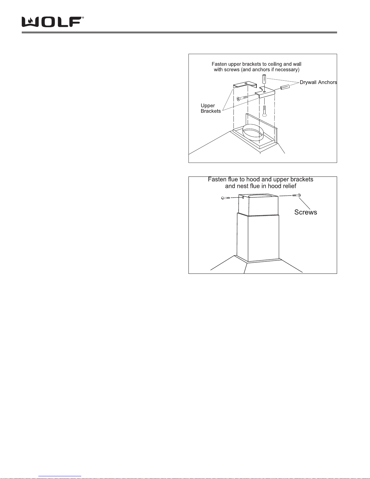
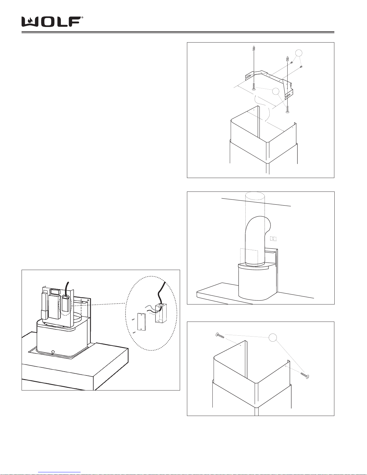
CT WALL HOOD DUCTWORK INSTALLATION
CONNECT DUCTWORK
Use the screws and wall anchors provided to secure the
upper brackets to the ceiling. Position the upper brackets
based on the dimension of the telescopic chimney fl ue.
(See Figure 2-13)
Use an 8” (203) round metal duct to connect the duct collar
on the hood to the ductwork above. Use duct tape to make
all joints secure and air tight.
Connect the upper section of the telescopic chimney fl ue to
the brackets with the screws provided. (See Figure 2-14)
Nest the bottom of the telescopic chimney fl ue into the
relief in the hood shell.
Installation InformationCT Hoods and DD Ventilation
Figure 2-13 Upper Flue Bracket Installation
Figure 2-14 Securing Inner Flue to Upper Flue Bracket
2-8
Installation Information CT Hoods and DD Ventilation
COOKTOP ISLAND HOOD INSTALLATION CONSIDERATIONS
TO REDUCE THE RISK OF FIRE, USE ONLY METAL DUCTWORK.
TO REDUCE THE RISK OF FIRE AND ELECTRIC SHOCK, THIS VENTILATION HOOD SHOULD ONLY BE
INSTALLED WITH BLOWERS MANUFACTURED BY WOLF APPLIANCE INC. AND SPECIFIED FOR USE WITH
THESE VENTILATION MODELS.
ISLAND HOOD INSTALLATION SPECIFICATIONS
AND PREPARATION FOR
MODEL IH4227
A straight, short duct run will allow 1.
the hood to perform more effi ciently.
Limit the number of elbows and transitions to as few as possible. Long
duct runs, elbows and transitions will
reduce the performance of the hood.
NOTE: All hoods must exhaust to the
outdoors.
NOTE: There is a possibility of noise issues, if a short duct run is coupled with a
remote blower.
Always use metal ducting. Do not 2.
use fl ex ducting.
Wolf recommends installing a back-3.
draft damper in all installations
(included with hood). In cold weather
installations a back-draft damper is
necessary to minimize the back-fl ow
of cold air into the room.
Wolf recommends the hood be in-4.
stalled 24” (610 mm) to 30” (762 mm)
above the cooking surface.
NOTE: Local building codes may require
the use of make-up air. Consult a local
HVAC professional for specifi c require-
ments.
ELECTRICAL REQUIREMENTS
Wolf cooktop wall hoods require a
separate, grounded, 110/120 VAC, 60 Hz
power supply. The service should have its
own 15 amp circuit breaker.
NOTE: You must follow all National
Electrical Code regulations. In addition,
be aware of local codes and ordinances
when installing your service.
Figure 2-15 Island Hood Installation Considerations
2-9
COOKTOP ISLAND HOOD INSTALLATION
DUE TO THE WEIGHT OF SOME HOODS, SEVERAL
PEOPLE MAN BE REQUIRED FOR A SAFE AND
PROPER INSTALLATION.
FRAMING MUST BE STRUCTURALLY TIED TOGETHER
AND TIED TO CEILING JOISTS TO PROVIDE ENOUGH
STRENGTH TO SUPPORT WEIGHT OF THE HOOD
AND INTERNAL BLOWER, IF APPLICABLE.
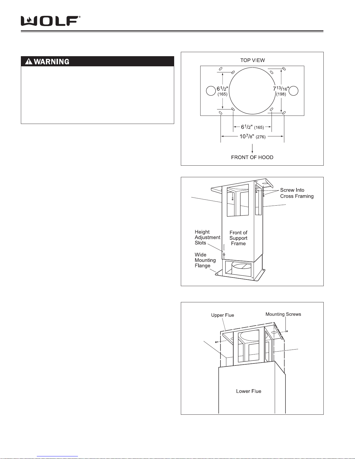
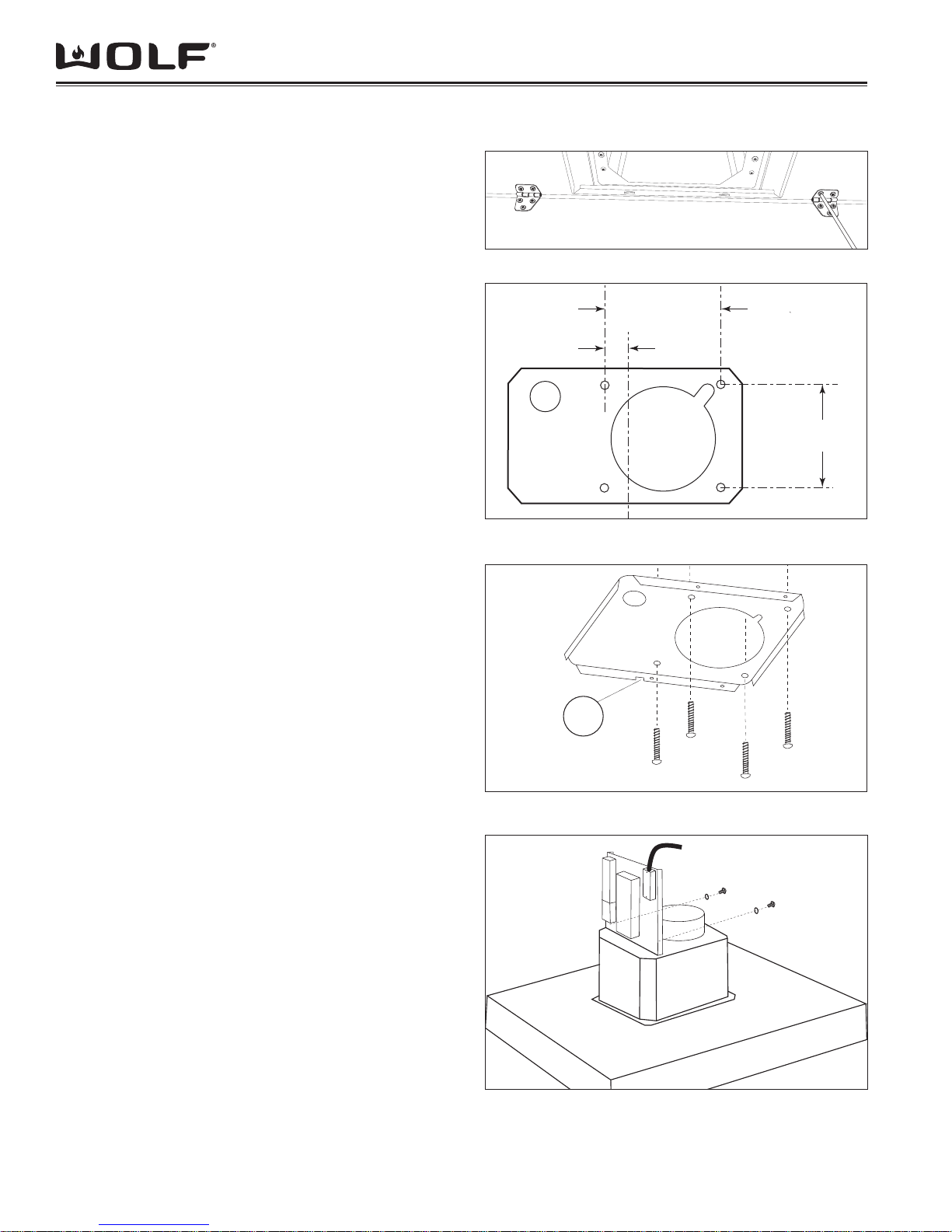
INSTALL SUPPORT SYSTEM
At the island hood installation location, install two-1.
by-four or 3/4”(19) plywood cross framing between
ceiling joists. Refer to the island hood mounting pattern
dimensions. (See Figure 2-16)
Finish the ceiling surface. Be sure to mark the location 2.
of the ceiling joists and cross framing.
Determine the desired orientation of the island hood. 3.
Note that the front designates the control side of the
hood.
Secure the upper half of the support frame to the joists 4.
and cross framing with four screws provided with your
hood. Make sure that the screws are driven into the
center of the joists and framing for maximum strength.
(See Figure 2-17)
Adjust the overall height of the support frame. Loosen 5.
and retighten the screws in the height adjustment slots
as necessary. (See Figure 2-17)
NOTE: The hood height is 11 1/4”(286) from the support
frame attachment point. The bottom of the hood must
be 24” (610)minimum and 30” (762) maximum from the
countertop.
Secure the upper telescopic chimney fl ue section to the 6.
upper support frame. (See Figure 2-18)
Installation InformationCT Hoods and DD Ventilation
Figure 2-16 Telescopic Flue Mounting
Figure 2-17 Support Frame
Figure 2-18 Upper Chimney Flue Mounting
2-10
Installation Information CT Hoods and DD Ventilation
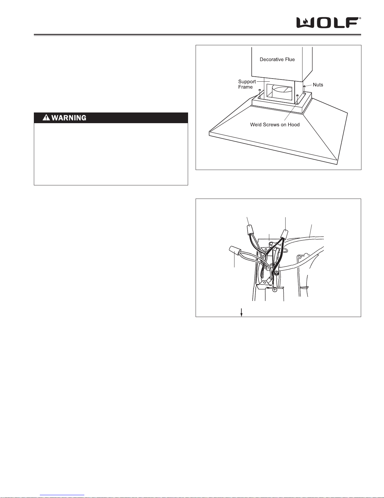
MOUNT HOOD TO SUPPORT FRAME
Temporarily secure the lower telescopic chimney 1.
fl ue section over the upper fl ue section.
Mount the hood to the support frame by aligning 2.
the four weld screws on the hood to the four holes
on the support frame. Use four nuts to secure the
hood to the support frame. (See Figure 2-19).
TO REDUCE THE RISK OF ELECTRICAL SHOCK,
THIS VENTILATION HOOD MUST BE PROPERLY
GROUNDED.
UNIT SHOULD BE CONNECTED ELECTRICALLY
BY A QUALIFIED ELECTRICIAN IN ACCORDANCE
WITH ALL APPLICABLE NATIONAL AND LOCAL
ELECTRICAL CODES.
LECTRICAL CONNECTIONS
E
Remove the cover from the rear electrical box 1.
knockout that faces the hood’s discharge collar.
Insert 6” (152) of 120 VAC power cable through 2.
the knockout opening. Secure the cable to the
electrical box with an appropriate connector.
Make electrical connections. Connect black to 3.
black, white to white and green/yellow to green or
bare wire. (See Figure 2-20)
Reinstall the electrical box cover and screws. Make 4.
sure that all wires are secure and that no wires are
pinched between the cover and box.
Use an 8” (203) round metal duct to connect the 5.
duct collar on the hood to the ductwork above. Use
duct tape to make all joints secure and air tight.
Slide the lower telescopic chimney fl ue section 6.
downward until it fi ts properly around the hood
shell.
Figure 2-19 Mounting Hood to Support System
Green/Yellow to
Green or
Bare Wire
White
to White
HOOD FRONT TOP OF HOOD SHELL
Black to
Rear
Electrical
Box
Figure 2-20 Electrical Connections
Black
Power Cable
120 V AC
Discharge
Collar
2-11
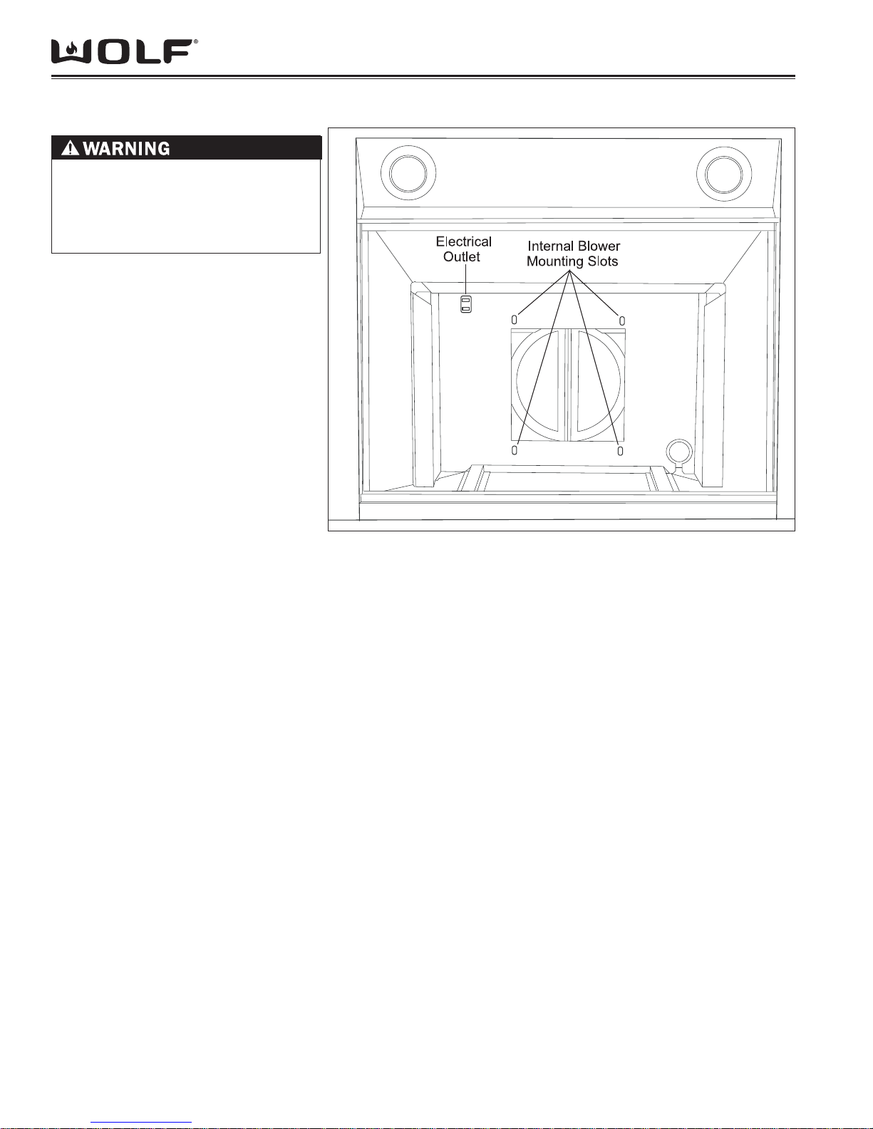
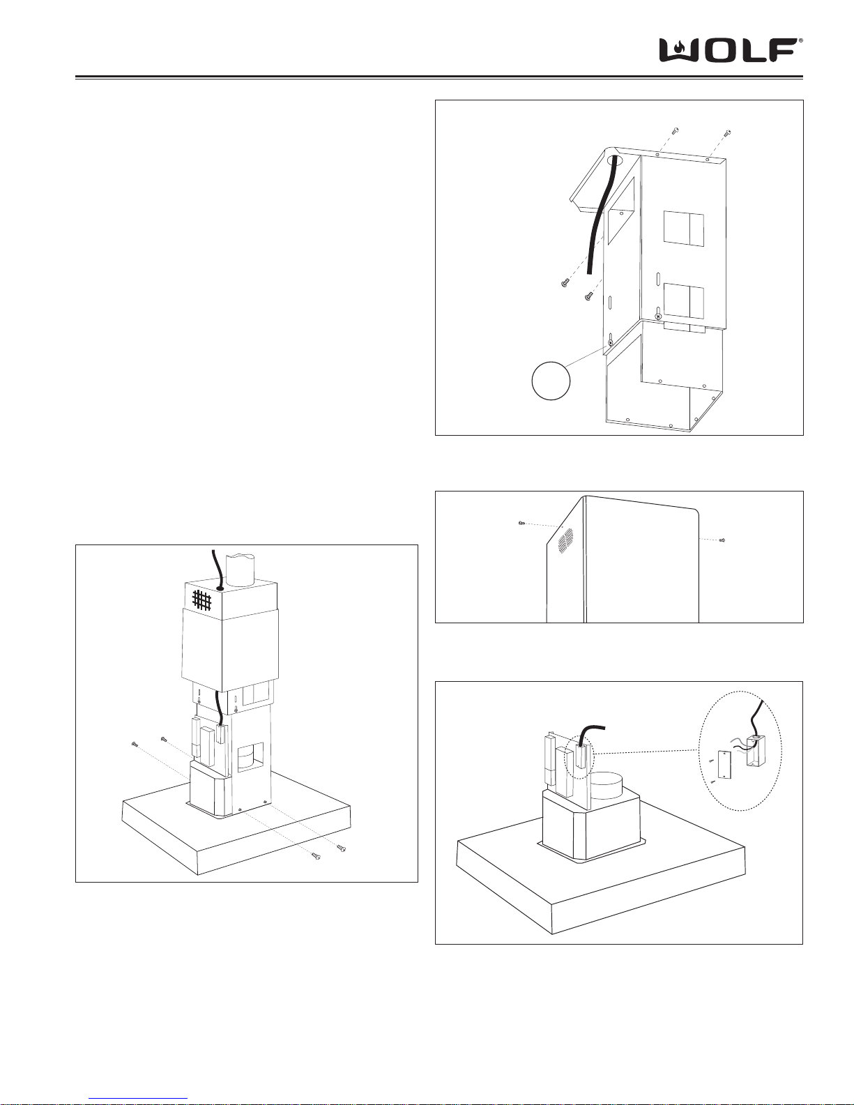
INTERNAL BLOWER INSTALLATION
TO REDUCE THE RISK OF
ELECTRICAL SHOCK, POWER
SHOULD BE TURNED OFF TO
UNIT BEFORE ATTEMPTING THE
FOLLOWING PROCEDURE.
INTERNAL BLOWER INSTALLATION
NOTE: Before turning the power on, make
sure blower control is in the “OFF” position. Use wire connectors or wire nuts
approved by UL or C/UL. Refer to installation instructions provided with each blower
to verify wall or roof cut-outs.
NOTE: Blower options vary with the cooking surface. Use only a Wolf blower with
the cooktop ventilation hood.
NOTE: For mounting and installation of
the internal blower, refer to the specifi c
installation instructions provided with each
blower.
Remove the hood fi lters.1.
Lift the blower into position inside 2.
the hood, the threaded studs on the
blower will slide through the slots provided in the upper panel.
Use four hex nuts provided with 3.
the blower to fasten the unit to four
threaded studs. (See Figure 2-21)
Plug the blowers’ single power cord 4.
(double for some blowers) into the
receptacle(s) inside the hood. Use the
clip on the hood to keep excess power
cord away from moving parts.
Reinstall the hood fi lters.5.
NOTE: Before turning the power on, make
sure the blower control is in the OFF position.
Installation InformationCT Hoods and DD Ventilation
Figure 2-21 Internal Blower Install
2-12

Installation Information CT Hoods and DD Ventilation
CTE WALL HOOD INSTALLATION CONSIDERATIONS
TO REDUCE THE RISK OF FIRE, USE ONLY METAL DUCTWORK.
TO REDUCE THE RISK OF FIRE AND ELECTRIC SHOCK, THIS VENTILATION HOOD SHOULD ONLY BE
INSTALLED WITH BLOWERS MANUFACTURED BY WOLF APPLIANCE INC. AND SPECIFIED FOR USE WITH
THESE VENTILATION MODELS.
INSTALLATION OPTIONS:
Ducted Installation. 1.
In a ducted installation, the hood aspirates the kitchen air saturated with fumes and odors, passes it through the
grease fi lter(s) and expels it to the outside through ductwork.
For this installation, a hood with an internal,
in-line or remote blower can be used. In-line blowers are located in ductwork between the hood and the outside.
For wall hoods, the remote blower can be mounted on the roof or an exterior wall. Wolf in-line and remote blower
assemblies are available through your Wolf dealer.
Recirculating Installation.2.
In a recirculating installation, the hood aspirates the kitchen air saturated with fumes and odors, purifi es it through
the grease fi lter(s) and charcoal fi lter and returns clean air into the room. For constant effi ciency, the charcoal fi lter
must be replaced periodically. For this installation, a recirculation kit available through your Wolf dealer will be
required.
NOTE: For Installation instructions for Recirculating Option please see Installation Manual that was provided with
the product.
LOW-PROFILE HOOD INSTALLATION SPECIFICATIONS AND PREPARATIONS
Decide where the ductwork will run between the hood and the outside. A straight, short duct run will allow the hood
to perform more effi ciently. Limit the number of elbows and transitions to as few as possible. Long duct runs, elbows
and transitions will reduce the performance of the hood. Wolf recommends the maximum linear duct run be no greater
than 50’ (15 m).
NOTE: There is a possibility of noise issues, if a short duct run is coupled with a remote blower.
Wolf recommends installing a backdraft damper in all installations. A backdraft damper is included with the hood. It is
built into the transition from the hood to the duct run. Unless you are using a remote blower, a roof or wall cap should
be installed. Connect ductwork to the cap and work back towards the hood. Use duct tape to seal the ductwork joints.
NOTE: Local building codes may require the use of make-up air. Consult a local HVAC professional for specifi c
requirements.
NOTE: Consult a qualifi ed HVAC Engineer for specifi c ducting applications.
2-13
Installation InformationCT Hoods and DD Ventilation
LOW-PROFILE WALL HOODS INSTALLATION SPECIFICATIONS AND PREPARATIONS
NOTE: This installation must be completed by a qualifi ed installer or Wolf authorized service center technician.
NOTE: Low Profi le Hoods are designed for use with a 6” diameter duct.
CTE W
ALL HOOD DUCTED INSTALLATION
Locate the electrical supply through the wall within the shaded area shown in Figure 23.1.
Install ductwork as outlined on page 2-13 & Figure 2-22.2.
If an optional backsplash is to be used, attach it to the fi nished wall. Secure the hood mounting brackets to the 3.
wall studs prior to installing the backsplash.
DUCT WORK
INSTALLATION
THROUGH
ROOF
29 1/8” (740)
TO
41 1/2” (1054)
HEIGHT
OF HOOD
24" (610)
TO
30" (762)
COUNTERTOP
TO B OTTOM
OF HOOD
DUCT WORK
INSTALLATION
THROUGH
WALL
173/4"
(451)
DEPTH OF HOOD
Figure 2-22 CTE Wall Hood Installation Considerations
2-14
Installation Information CT Hoods and DD Ventilation
E
LECTRICAL REQUIREMENTS
Wolf low-profi le hoods require a separate, grounded,
110/120 VAC, 60 Hz power supply. The service should
have its own 15 amp circuit breaker.
NOTE: You must follow all National Electrical Code
regulations. In addition, be aware of local codes and
ordinances when installing your service.
IXING TO THE WALL
F
Draw a line on the wall in vertical line with your hood. 1.
Mark the fi rst two holes to be drilled in the wall, re-
specting the distances indicated in Figure 23. Drill the
two holes and fi t the screw anchors provided.
For best capture of cooking impurities, the bottom 2.
of the hood should be a minimum of 24” (610) and a
maximum of 30” (762) above THE COUNTERTOP.
Fix the metal bracket (A) to the wall using the two 3.
holes just drilled as shown in Figure 24. The screws
for fi xing the bracket are provided. Use the two cut-out
triangles on the bracket to position it exactly along the
vertical axis of the hood.
Hang the hood on the bracket as shown in Figure 4.
25. Adjust the horizontal position moving the hood
to the right or left so that it is aligned with the wall
units. When adjustment has been completed, without
removing the hood, mark the other four holes to be
drilled (C) in the wall. Remove the hood and drill the
holes marked (5/16” diameter). Then use the four
screw anchors and the four screws provided for fi nal
fi xing.
Mount the plate of the electrical system fi xing it with 5.
three screws.
FIXING THE TELESCOPIC FLUE
Adjust the width of the support bracket (D) of the 1.
telescopic fl ue by means of the screws (E) as shown
in Figure 26. Then, by means of the screw anchors
and screws (F) provided, fi x the bracket to the ceiling
in such a way that it is positioned along the axis with
your hood.
Connect the air outlet pipe to the air vent of the hood. 2.
Use a fl exible pipe and lock it to the air vent of the
hood with a metal hose clamp as shown in Figure 27
(pipe and clamp are not provided).
For exhaust hoods, turn the upper fl ue over so that 3.
the air exhaust grid is in the lower section.
Figure 2-23 CTE Wall Hood Mounting Plate Placement
Figure 2-24 CTE Wall Hood Mounting Plate Mounting
5/16"
DIAMETER
4.8 x 38mm
A
5 1/16”
(129)
E
13 3/8” (340)
24" to 30" (610 – 762)
TO COOKING SURFACE
E
C
4.8 x 38 mm
Figure 2-25 CTE Wall Hood Mounting
2-15
WIRING
NOTE: The ventilation hood must be properly grounded. It should be installed by a qualifi ed electrician in ac-
cordance with all applicable national and local electrical
codes.
Run supply conductors to the hood wiring box 1.
marked “120 VAC input”.
Remove the cover from the wiring box and remove 2.
one knockout as shown in Figure 28.
Secure the conduit to the wiring box through a 3.
conduit connector.
Make electrical connections at the hood. Connect 4.
white-to-white, black-to-black and green-to-ground.
Replace the wiring box cover and screws. Make 5.
sure wires are not pinched between the cover and
box.
INAL STEP
F
Insert the fl ue extensions setting them on the hood.
Extend the upper fl ue to the ceiling and secure with the
two screws (H) as shown in Figure 29.
Installation InformationCT Hoods and DD Ventilation
E
F
=
Figure 2-26 CTE Wall Hood Flue Support Bracket
Figure 2-28 CTE Wall Hood Electrical Connection
Figure 2-27 CTE Wall Hood Air Outlet Pipe
3.9 x 9.5mm
H
BOX MARKED
120 VAC INPUT
Figure 2-29 CTE Wall Hood Flue Securing
2-16
Installation Information CT Hoods and DD Ventilation
TO REDUCE THE RISK OF FIRE, USE ONLY METAL DUCTWORK.
TO REDUCE THE RISK OF FIRE AND ELECTRIC SHOCK, THIS VENTILATION HOOD SHOULD ONLY BE
INSTALLED WITH BLOWERS MANUFACTURED BY WOLF APPLIANCE INC. AND SPECIFIED FOR USE WITH
THESE VENTILATION MODELS.
LOW-PROFILE ISLAND HOOD INSTALLATION SPECIFICATIONS AND PREPARATION
NOTE: This installation must be completed by a qualifi ed installer or Wolf authorized service center technician.
Locate the electrical supply through the ceiling inside the area of the fl ue.1.
Install ductwork as outlined on page 2-13 & Figure 2-30.2.
DUCT WORK
INS TALLATION
TH ROUGH
28 1/4” (718)
TO
41 1/2” (1054)
HEIGHT
OF HOOD
24" (610)
TO
30" (762)
COUNTERTOP
TO BOTTOM
OF HOOD
ROOF
215/8" (549)
DEPTH OF HOOD
DUCTWORK
INSTALLATION
THROUGH EAVE –
INTERNAL
BLOWER ONLY
Figure 2-30 CTEI Hood Installation Considerations
2-17
CTE ISLAND HOOD INSTALLATION
ELECTRICAL REQUIREMENTS
Wolf low-profi le hoods require a separate, grounded,
110/120 VAC, 60 Hz power supply. The service should
have its own 15 amp circuit breaker.
NOTE: You must follow all National Electrical Code
regulations. In addition, be aware of local codes and
ordinances when installing your service.
FIXING TO THE CEILING
Mount the metal panel with four screws as shown in 1.
Figure 31.
Using the drilling template, drill the holes for fi xing to 2.
the ceiling on the vertical side of your hood. The center
line of the mounting plate (Figure 32) is in line with
the center of the control panel. Carefully observe this
indication to ensure proper alignment of the hood with
the cooking product.
Fix the bracket to the ceiling using the screws and 3.
screw anchors provided as shown in Figure 33.
NOTE: The position of the bracket determines the fi nal
position of the hood. The side with the slot (B) corresponds
to the side opposite the controls.
Assemble the plate of the electrical system fi xing it with 4.
two screws and two metal washers as shown in Figure
34.
Fix the telescopic fl ue to the bracket by means of four 5.
screws (provided), running the air evacuation pipe
through the telescopic fl ue and the electric power cable
through the special hole in the bracket as shown in
Figure 35.
Adjust the height of the telescopic fl ue by means of the 6.
four retaining screws (C) shown in Figure 35. Take into
account that the height of the hood is 3 1/8” (79) and
the bottom of the hood should be a minimum of 24”
(610) and a maximum of 30” (762) above the countertop.
Take the upper fl ue (with the round slots) and slide it on 7.
the telescopic fl ue with the slots facing upwards. Attach
the fl ue to the bracket with two screws as shown in
Figure 36.
Take the lower fl ue and slide it over the upper fl ue, to 8.
the top and secure it in that position using adhesive
tape.
Raise the hood to the telescopic fl ue and connect 9.
the air outlet duct to the hood. Attach the hood to the
telescopic fl ue by means of four screws (provided) as
shown in Figure 37.
Installation InformationCT Hoods and DD Ventilation
Figure 2-31 CTE Island Hood Metal Panel Mounting
5 15/16” (151)
1 3/8” (35)
5 15/16” (151)
Figure 2-32 CTE Island Hood Plate Dimensions
B
4.5 x 60mm
Figure 2-33 CTE Island Hood Ceiling Plate Mounting
3.9 x 9.5mm
Figure 2-34 CTE Island Hood Control Plate
2-18
Installation Information CT Hoods and DD Ventilation
WIRING
NOTE: The ventilation hood must be properly grounded. It should be installed by a qualifi ed electrician in ac-
cordance with all applicable national and local electrical
codes.
Run supply conductors to the hood wiring box 1.
marked “120 VAC input”.
Remove the cover from the wiring box and remove 2.
one knockout as shown in Figure 38.
Secure the conduit to the wiring box through a 3.
conduit connector.
Make electrical connections at the hood. Connect 4.
white-to-white, black-to-black and green-to-ground.
Replace the wiring box cover and screws. Make 5.
sure wires are not pinched between the cover and
box.
INAL STEP
F
Remove the adhesive tape and slide the lower fl ue
downward, placing it gently onto the hood base. Installation is now complete and the grease fi lters can be
installed.
3.9 x 9.5mm
C
Figure 2-35 CTE Island Hood Telescopic Flue Mounting
Figure 2-37 CTE Island Hood to Telescopic Flue
3.9 x 9.5mm
Figure 2-36 CTE Island Hood Upper Flue Mounting
BOX MARKED
120 VAC INPUT
Figure 2-38 CTE Island Hood Electric Hookup
2-19
REMOTE BLOWER INSTALLATION
TO REDUCE THE RISK OF ELECTRICAL SHOCK,
POWER SHOULD BE TURNED OFF TO UNIT
BEFORE A TTEMPTING THE FOLLOWING
PROCEDURE.
REMOTE BLOWER INSTALLATION
NOTE: Before turning the power on, make sure the
blower is in the “OFF” position. Use wire connectors or
wire nuts approved by UL or C/UL..
NOTE: Detailed instructions of Remote Blower
installation are provided with the blower. Refer to
installation instructions provided with each blower to
verify wall or roof cut-outs. The following information is
simply intended to summarize the process.
Locate the blower so the length of the duct run 1.
and number of elbows and transitions are kept to a
minimum.
Where possible, blower should be located between 2.
wall studs or roof rafters.
Avoid pipes, wires or other ductwork that may be 3.
running through the wall.
Be sure that there is enough space for any 4.
transitions that may be needed between the blower
and the connecting ductwork.
For best performance, locate transitions nearest 5.
the blower.
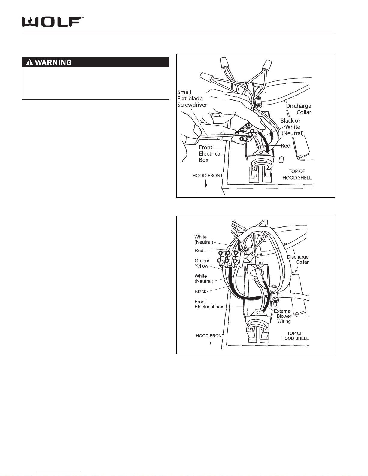
CONNECT REMOTE BLOWER
NOTE: Always refer to all blower installation
instructions provided with the blower for additional
mounting and wiring instructions.
Remove the cover from the front of the electrical 1.
box. Remove the electrical box knockout that
faces the hood’s discharge collar.
Disconnect the red, black or white wires using a 2.
fl at-blade screwdriver. (See Figure 2-39)
Insert 6” (152) of the remote blower wiring through 3.
the knockout opening. Secure the cable to the
electrical box with an appropriate connector. Use
wire connectors or wire nuts approved by UL or C/
UL.
Attach the remote blower wiring where the wires 4.
were removed in step 2. (See Figure 2-40)
Re-install wiring box cover and screws. Make sure 5.
all wires are secure and that no wires are pinched
between cover and box.
NOTE: Before turning the power on to the ventilation
hood, make sure the blower is in the OFF position.
Installation InformationCT Hoods and DD Ventilation
Figure 2-39 Remote Blower Electrical Connections Prepare
Figure 2-40 Remote Blower Electrical Connections
2-20
Installation Information CT Hoods and DD Ventilation
DOWNDRAFT DIMENSIONS
TO REDUCE THE RISK OF FIRE AND ELECTRIC SHOCK, THIS VENTILATION HOOD SHOULD ONLY BE
INSTALLED WITH BLOWERS MANUFACTURED BY WOLF APPLIANCE INC. AND SPECIFIED FOR USE WITH
THESE VENTILATION MODELS.
NOTE: Wolf downdraft ventilation systems are recommended for use with Wolf framed electric, gas, induction and
multi-function cooktops. They cannot be used with unframed electric cooktops and are not recommended for use with
the electric grill, steamer and fryer modules. A Pro ventilation hood must be used with Wolf dual fuel ranges, gas
ranges and rangetops.
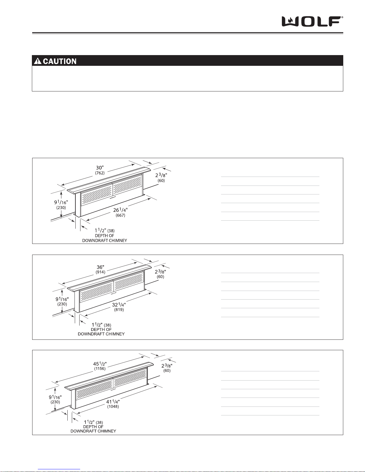
Wolf downdraft ventilation systems are available in 30” (762), 36” (914) and 45-1/2”(1156) widths. The downdraft
should be at least as wide as the cooktop. Models DD30I, DD36I and DD45I include a 500CFM internal blower. Models DD30R, DD36R and DD45R are shipped without a blower assembly.
MODELS DD30I AND DD30R
O )267("03htdiW llarev
Width of Chimney 261/4"(667)
Overall Height
Depth of Chimney 11/2"(38)
(above countertop)
91/16"(230)
3
2htpeD llarevO
/8"(60)
Dimensions may vary to
Figure 2-41 Models DD30I & DD30R
MODELS DD36I AND DD36R
Width of Chimney 321/4"(819)
Overall Height
Overall Depth 23/8"(60)
Depth of Chimney 11/2"(38)
Dimensions may vary to
Figure 2-42 Models DD36I & DD36R
MODELS DD45I AND DD45R
Overall Width 451/2" (1156)
Width of Chimney 411/4" (1048)
Overall Height
Overall Depth 23/8"(60)
Depth of Chimney 11/2"(38)
1
+
/8"(3).
–
(above counter top)
1
+
/8"(3).
–
(above countertop)
)419("63htdiW llarevO
91/16" (230)
91/16" (230)
Dimensions may vary to
Figure 2-43 Models DD45I & DD45R
2-21
1
+
–
/8"(3).
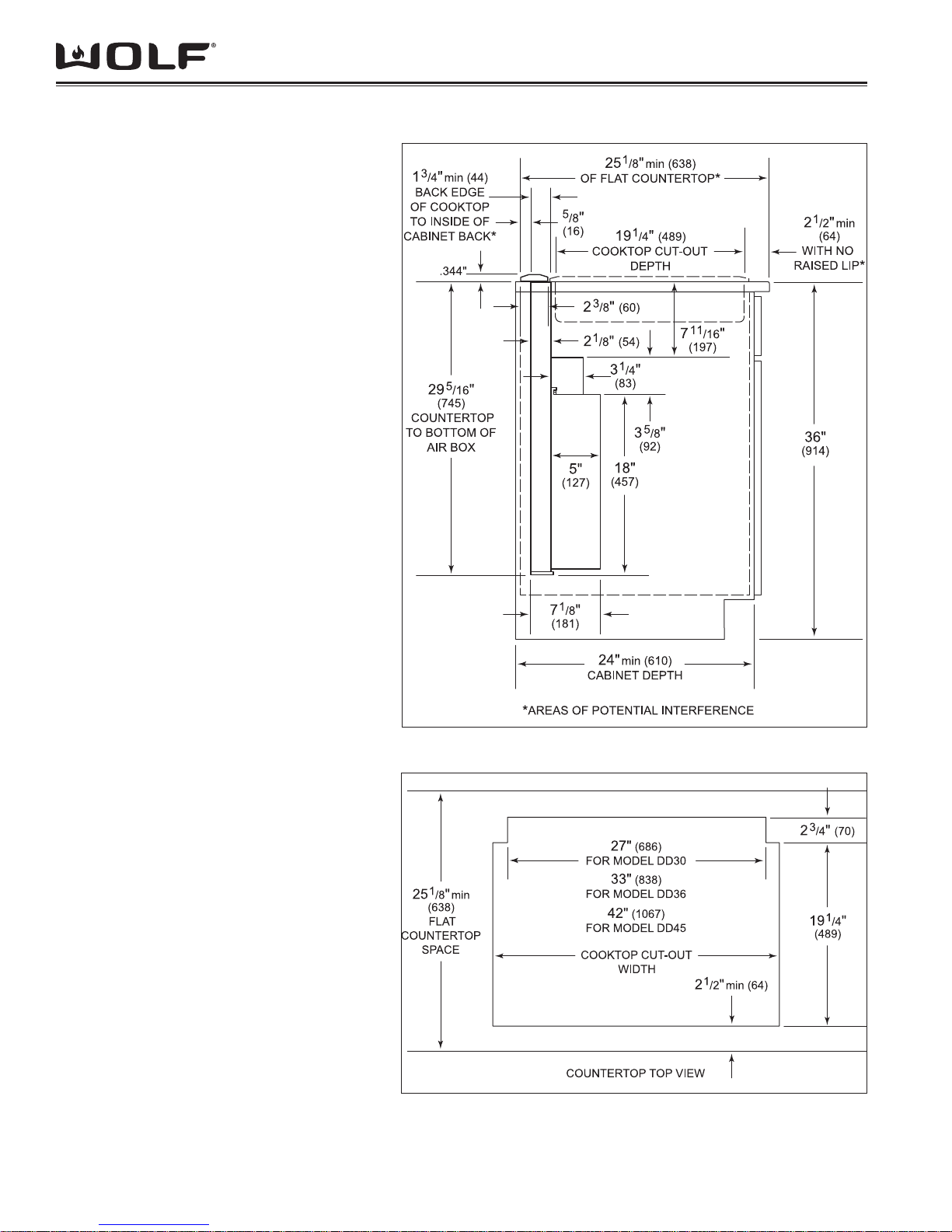
DOWNDRAFT INSTALLATION SPECIFICATIONS
INSTALLATION SPECIFICATIONS
Wolf downdraft Model DD30 will fi t most 30”
(762) wide cabinets, Model DD36 will fi t most
36” (914) wide cabinets and Model DD45 will
fi t most 45-1/2”(1156) wide cabinets. It is
recommended that oversized cabinets be used
for easier installation. Cabinet backs may need
to be removed. Wolf downdraft ventilation
systems can be mounted in an island, peninsula
or standard wall location.
NOTE: To install a downdraft system and a
Wolf cooktop, you must allow for a minimum
25-1/8”(638) fl at counter space from front
to back. A countertop with a raised lip or
backsplash may not allow enough space for
proper installation. 2-3/8”(60) of fl at countertop
is required behind the cooktop and 1-3/4”(44)
is necessary between the back edge of the
cooktop and inside of cabinet back.
If downdraft Model DD30 is installed in
combination with two cooktops or integrated
modules, an integrated module support
(available as a sales accessory) for downdraft
ventilation is required. Model DD45 does not
require this accessory. If optional fi ller strips are
used with the cooktops or modules, be aware
that they are different for the Model DD30 and
DD45. Be sure to use the correct fi ller strip.
For installation of a downdraft system with
a cooktop, refer to the cooktop installation
instructions for the dimensions of the cooktop,
countertop cut-out and cabinet requirements.
The depth of the cooktop may vary and will
affect the location of the downdraft in the
countertop. Figure 2-45 provides countertop
cut-out dimensions for downdraft Models DD30,
DD36 and DD45 installed with a Wolf 30”(762)
or 36” (914) cooktop or combination of cooktop
and/or modules.
Installation InformationCT Hoods and DD Ventilation
Figure 2-44 Side View Installation Dimensions
Figure 2-45 Top View Installation Dimensions
2-22
 Loading...