

Wolf ICBCT15G/S, ICBCT15G/S-LP, ICBCT30G/S-LP, ICBCT36G/S, ICBCT36G/S-LP Installation Instructions Manual
...
GAS COOKTOPS
INSTALLATION INSTRUCTIONS
INSTRUCCIONES DE INSTALACIÓN
INSTRUCTIONS D’INSTALLATION
ISTRUZIONI PER L’INSTALLAZIONE
INSTALLATIONSANWEISUNGEN


N G L I S H 4
E
S P Ã N O L 1 8
E
F R A N Ç A I S 3 2
I TA L I AN O 4 6
D E U T S C H 6 0
3
C O N TA C T
I N F O R M A T IO N
Website:
wolfappliance.com
As you follow these instruc tions, you will
notice WARNING and CAUTION symbols. This
blocked information is impor tant for the safe
and efficient installation of Wolf equipment.
There are two types of potential hazards that
may occur during installation.
WOLF®is a registered trademark of Wolf Appliance, Inc.
signals a situation where minor injury or
product damage may occur if you do not
follow instructions.
states a hazard that may cause serious
injury or death if precautions are not
followed.
Another footnote we would like to identify is
IMPORTANT NOTE: This highlights information that is especially relevant to a problemfree installation.
W O L F GAS CO O KTO P S
IN S TA LL AT I ON R E Q U I R E M E N T S
WHAT TO DO IF YOU SMELL GAS:
This appliance shall be installed
in accordance with the regulations in force and only used in a
well ventilated space. Read the
instructions before installing or
using this appliance.
IMPORTANT NOTE:
Installation and service must be
performed by a qualified installer,
service agency or the gas supplier.
Do not store or use gasoline or
other flammable vapors and liquids
in the vicinity of this or any other
appliance.
The use of a gas cooking appliance
results in the production of heat and
moisture in the room in which it is
installed. Ensure that the kitchen is
well ventilated; keep natural ventilation holes open or install a mechanical ventilation device (mechanical
extractor hood)
Do not try to light any appliance.
Do not touch any electrical switch.
Do not use any phone in your
building.
Immediately call your gas supplier
from a neighbor’s phone. Follow
the gas supplier’s instructions.
If you cannot reach your gas
supplier, call the fire department.
Prolonged intensive use of the appliance may for additional ventilation,
for example opening of a window, or
more effective ventilation, for
example increasing the level of
mechanical ventilation where
present.
5

W O L F GAS C OO K TOP S
AT I NG P LAT E
R
I N FO R M AT IO N
Model Number
Serial Number
IN S TA LL AT I ON R E Q U I R E M E N T S
IMPORTANT NOTE: This installation must
be completed by a qualified installer,
service agency or gas supplier.
IMPORTANT NOTE:
Save these Installation
Instructions for the local inspector’s use.
Please read the entire Installation Instructions prior to installation.
Installer:
please retain these instructions
for local inspector’s reference, then leave
them with the homeowner.
Homeowner:
please read and keep these
instructions for future reference and be sure
to read the entire Use & Care Information
prior to use.
IMPORTANT NOTE:
This appliance must be
installed in accordance with local codes. The
correct voltage, frequency and amperage must
be supplied to the appliance from a dedicated,
grounded circuit which is protected by a
properly sized circuit breaker or time delay
fuse. The proper voltage, frequency, and
amperage ratings are listed on the product
rating plate.
BE F OR E YO U S TA RT
Proper installation is your responsibility.
Have a qualified technician install this
cooktop. You must also assure that electrical installation is adequate and in compliance with all local codes and ordinances.
Prior to installation, ensure that the local
distribution conditions (nature of the gas
and gas pressure) and the adjustment of
the appliance are compatible.
Proper gas supply connection must be
available; refer to Gas Supply Requirements
on page 12. Electrical ground is required;
see Electrical Requirements on page 13.
The adjustment conditions for this appliance are stated on the label (or rating
plate). The data plate can be found on the
underside of the cooktop.
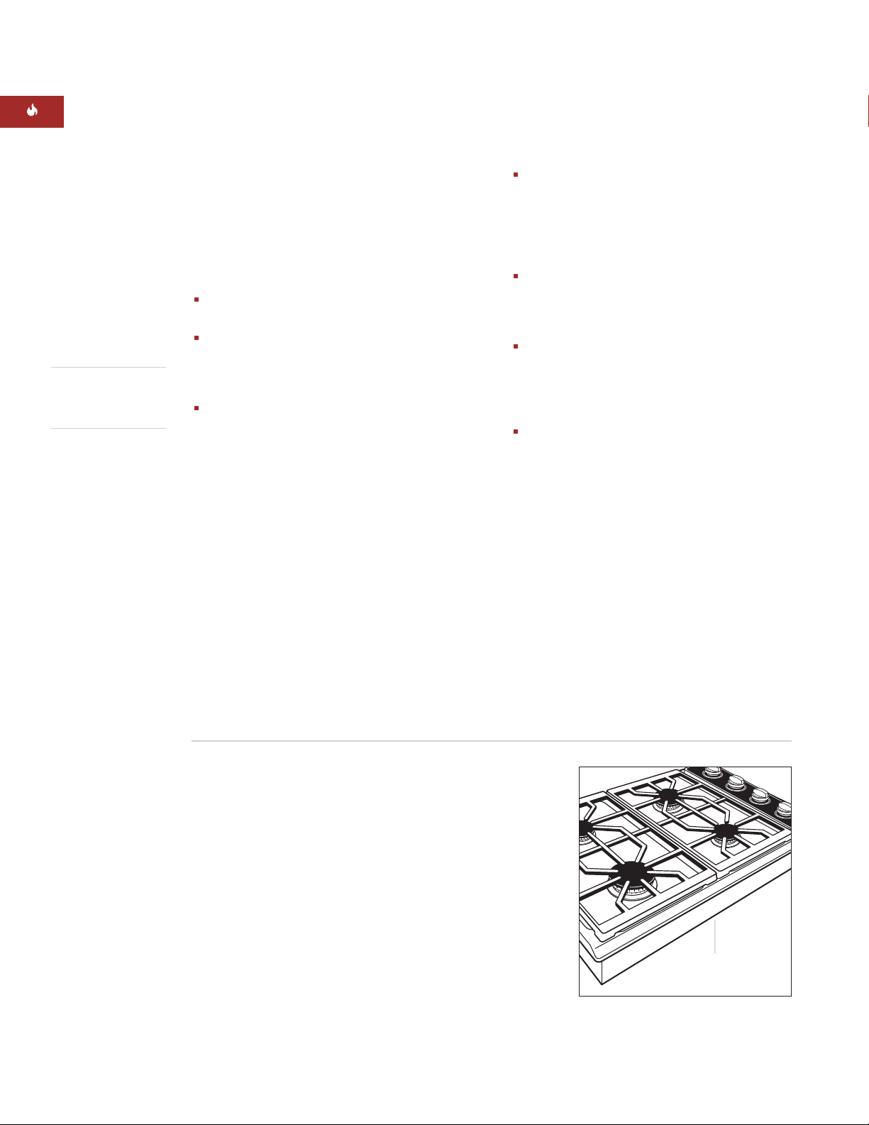
Record the model and serial numbers before
installing the cooktop. Both numbers are listed
on the rating plate, located on the underside of
the cooktop. Refer to the illustration below.
Location of rating
plate under cooktop
Rating plate location
6

IN S TA LL AT I ON I N S T R U C T I O N S
BE F OR E YO U S TA RT
Check the location where the cooktop will
be installed. The location should be away
from strong draft areas, such as windows,
doors and strong heating vents or fans. Do
not obstruct flow of combustion and
ventilation air.
This appliance is not connected to a
combustion products evacuation device. It
shall be installed and connected in accordance with current installation regulations.
Particular attention shall be given to the
relevant requirements regarding ventilation.
This cooktop is intended for indoor use.
SI T E P R EP A R AT I O N
C O U N T E R T O P C U T- O UT D I M E N S I O N S
IMPORTANT NOTE:
Countertop opening
dimensions shown on the following pages
must be used. The dimensions shown provide
for required clearances.
These cooktops are designed to fit a standard
610 mm deep base cabinet with a 635 mm
deep countertop. Before making the countertop cut-out, verify that the cooktop will clear
the side walls of the base cabinet below. There
should be at least 140 mm clearance between
the countertop and any combustible surface
directly below the unit.
L O C AT I O N R EQ U I RE M E NT S
Illustrations on the following pages provide the
overall dimensions, countertop cut-out and
installation specifications for Wolf gas
cooktops. Maintain the following minimum
installation dimensions:
Minimum horizontal clearance from the
sides and back of the cooktop cut-out to
adjacent vertical combustible construction,
extending a minimum of 457 mm above the
countertop, is as follows: 178 mm from side
edges of cut-out for the 381 mm cooktop;
229 mm from side edges of cut-out for the
762 mm and 914 mm cooktops; 64 mm
from rear edge of cut-out.
Minimum vertical distance between the
countertop and combustible materials
above the cooktop must be 762 mm.
Maximum 330 mm depth of overhead side
cabinets directly above and within side
clearance.
IMPORTANT NOTE:
When installing a ventilation hood, refer to the specific requirements
of the hood for the minimum dimension to
countertop.
Failure to locate the cooktop without the
proper clearances will result in a fire
hazard.
IMPORTANT NOTE:
Do not seal the cooktop
to the countertop. It must be removed if
service is necessary.
7
914 mm
FLOOR TO
COUNTERTOP
762 mm min
COUNTERTOP
TO COMBUSTIBLE
MATERIALS
SEE COUNTERTOP
CUT-OUT BELOW
356 mm
CUT-OUT
WIDTH
COUNTERTOP CUT-OUT
FRONT
489 mm
CUT-OUT
DEPTH
64 mm min
178 mm TO
COMBUSTIBLE*
178 mm TO
COMBUSTIBLE*
SIDE
CABINET
330 mm
max
*Minimum clearance from cooktop cut-out to combustible materials up to 457 mm above countertop.
NOTE: Application shown allows for installation of two 381 mm modules side by side.
E
381 mm
381
mm
102 mm
457 mm min
127
mm
LOCATION OF GAS
AND ELECTRICAL
EXTENDS ON FLOOR
G
64
mm*
W O L F GAS C OO K TOP S
381 mm
OVER ALL WID TH
533 mm
OVERALL
DEPTH
102 mm
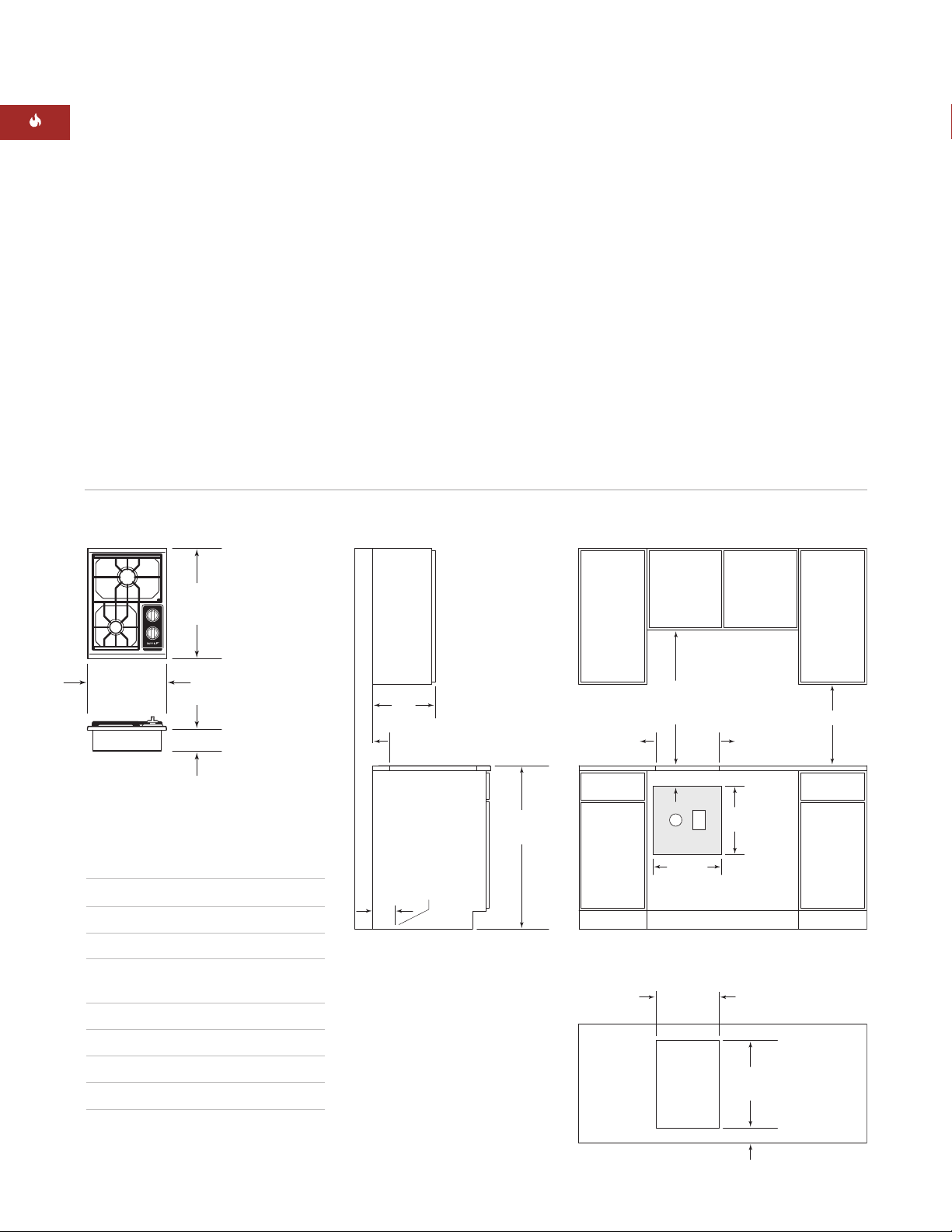
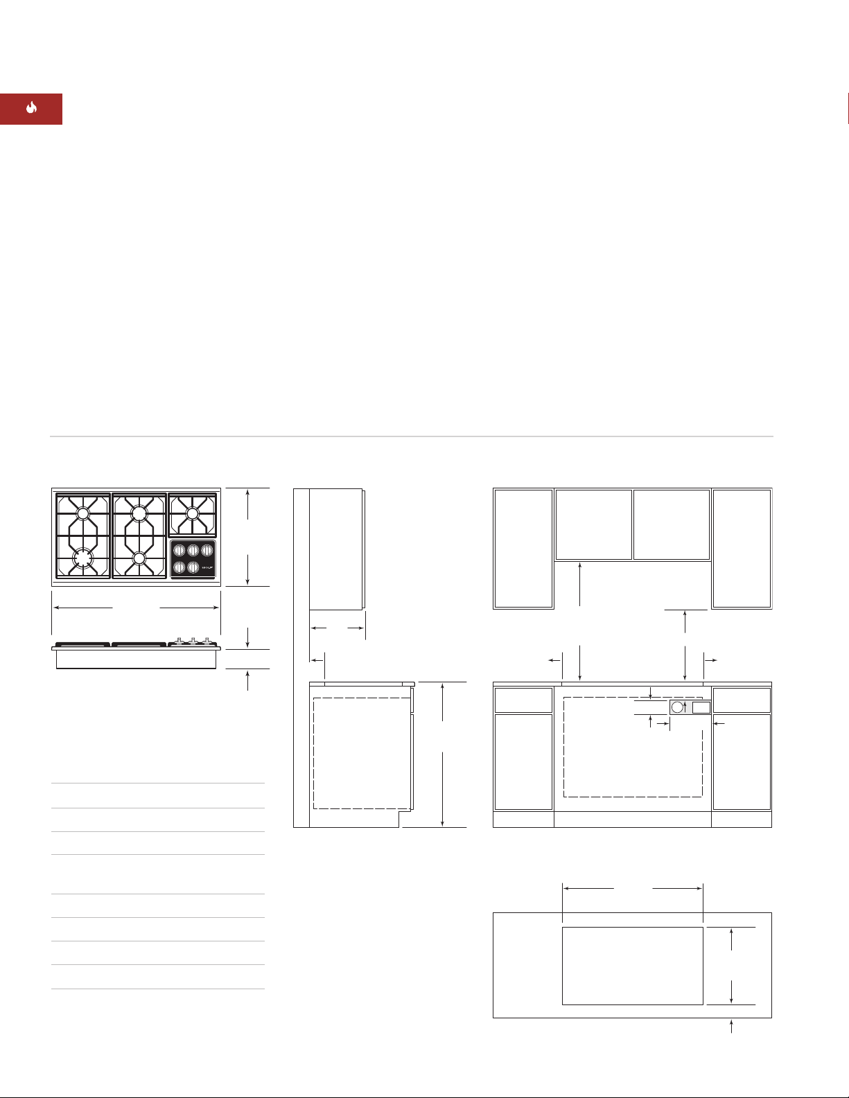
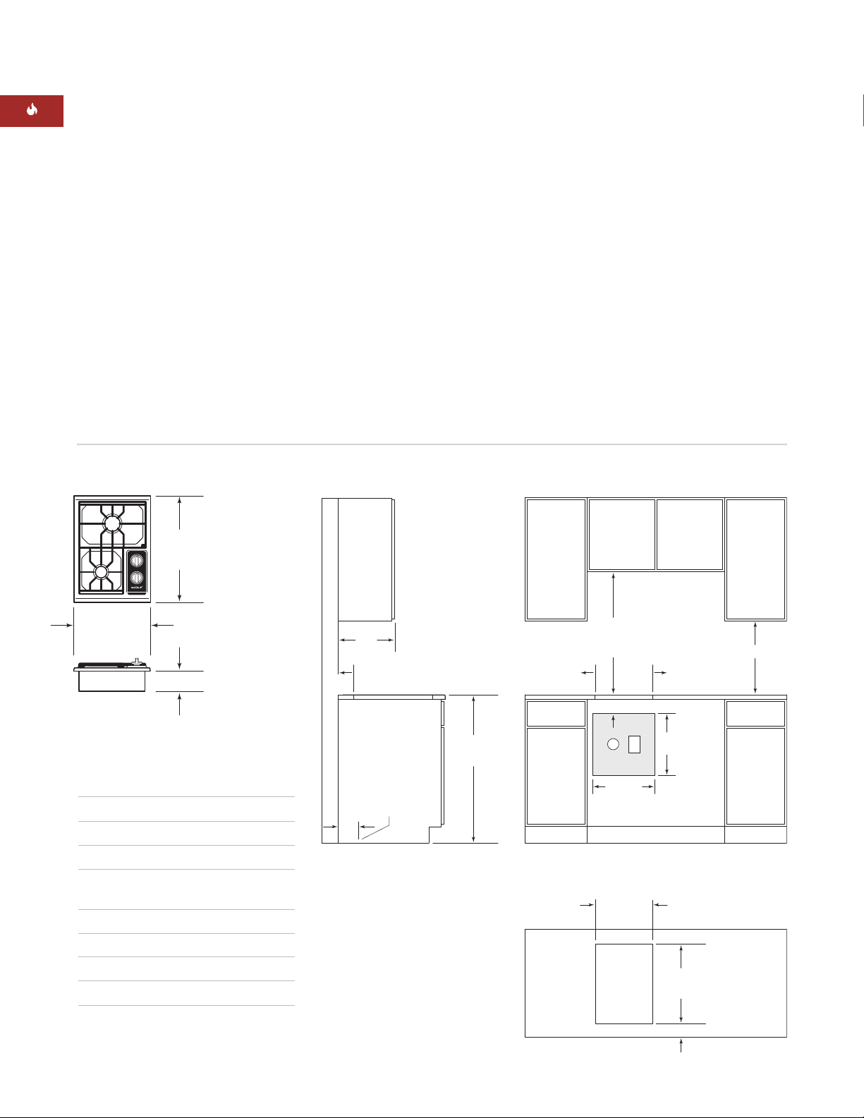
IN S TA LL AT I ON S P E C I F I C AT I O N S
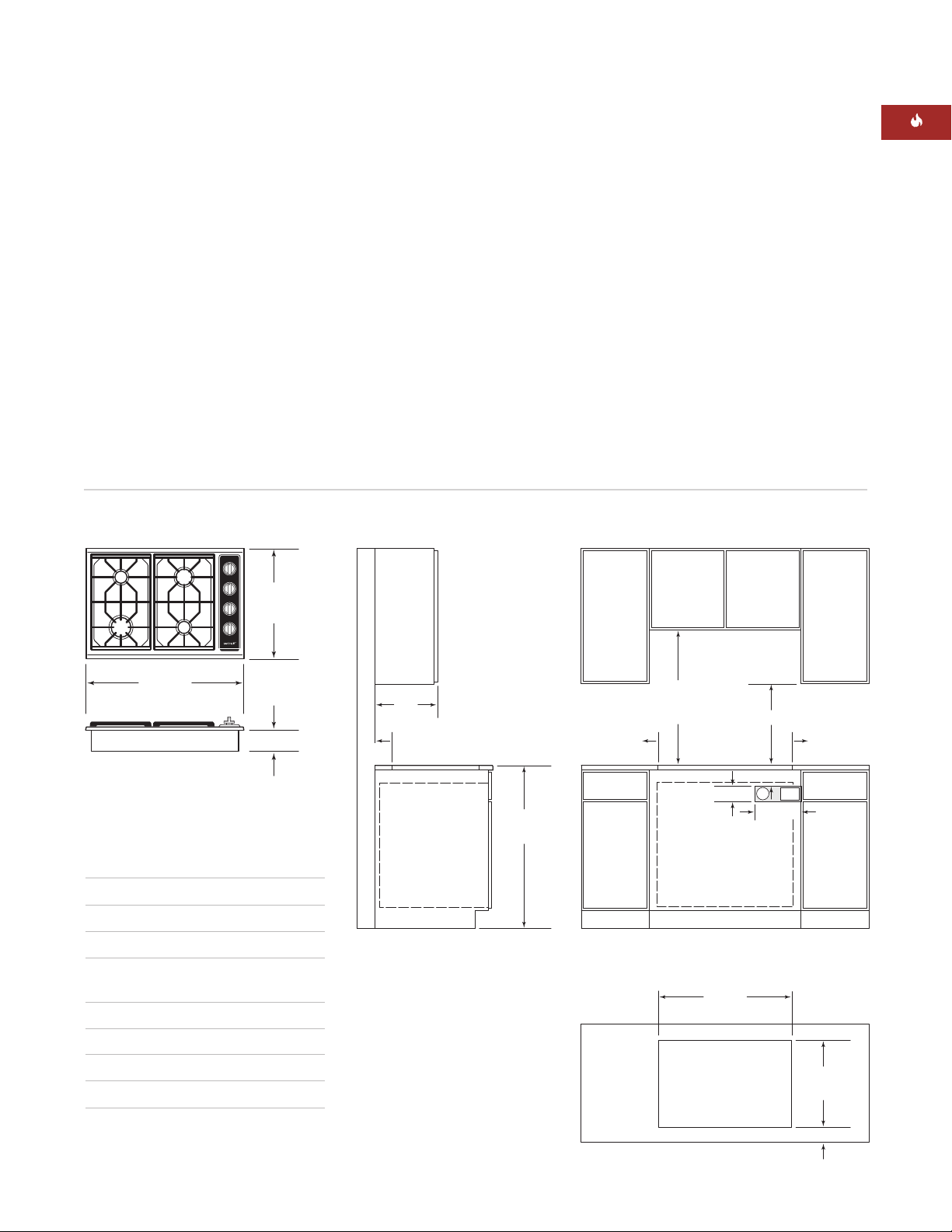
The illustrations below provide the overall
dimensions, countertop cut-out and installation
specifications for Model ICBCT15G.
For Model ICBCT15G, the gas service may be
supplied through the floor if the cooktop is not
installed above an oven. Refer to the illustration
for specifics on placement of gas and electrical.
I N S TA LL AT I O N SP E C IF I C AT I O N S – M O DE L I C BC T 1 5G
IMPORTANT NOTE:
When multiple cooktop
units are installed side by side, refer to the
countertop cut-out dimensions on page 11.
Overall Dimensions
M O D E L I CB C T 15 G
D I M E N S I O N S
Overall Width 381 mm
Overall Height 102 mm
Overall Depth 533 mm
Recommended
Cabinet Width 838 mm
Minimum Cabinet Depth 578 mm
Minimum Height Clearance 102 mm
Cut-Out Width 356 mm
Cut-Out Depth 489 mm
Unit dimensions may vary to ±3 mm.
8
457 mm min
914 mm
FLOOR TO
COUNTERTOP
762 mm
min
C
OUNTERTOP
TO COMBUSTIBLE
MATERIALS
762 mm OVEN OPENING
102 mm
254 mm
89 mm
E
SEE COUNTERTOP
CUT-OUT BELOW
229 mm TO
COMBUSTIBLE*
229 mm TO
COMBUSTIBLE*
64
mm*
SIDE
CABINET
330 mm
m
ax
737 mm
CUT-OUT WIDTH
COUNTERTOP CUT-OUT
FRONT
489 mm
CUT-OUT
DEPTH
64 mm min
*Minimum clearance from cooktop cut-out to combustible materials up to 457 mm above countertop.
NOTE: Gas and electrical location applies only to installation with built-in oven.
G
IN S TA LL AT I ON I N S T R U C T I O N S
533 mm
FONDO
T
OTAL
762 mm
ANCHURA TOTAL
102 mm
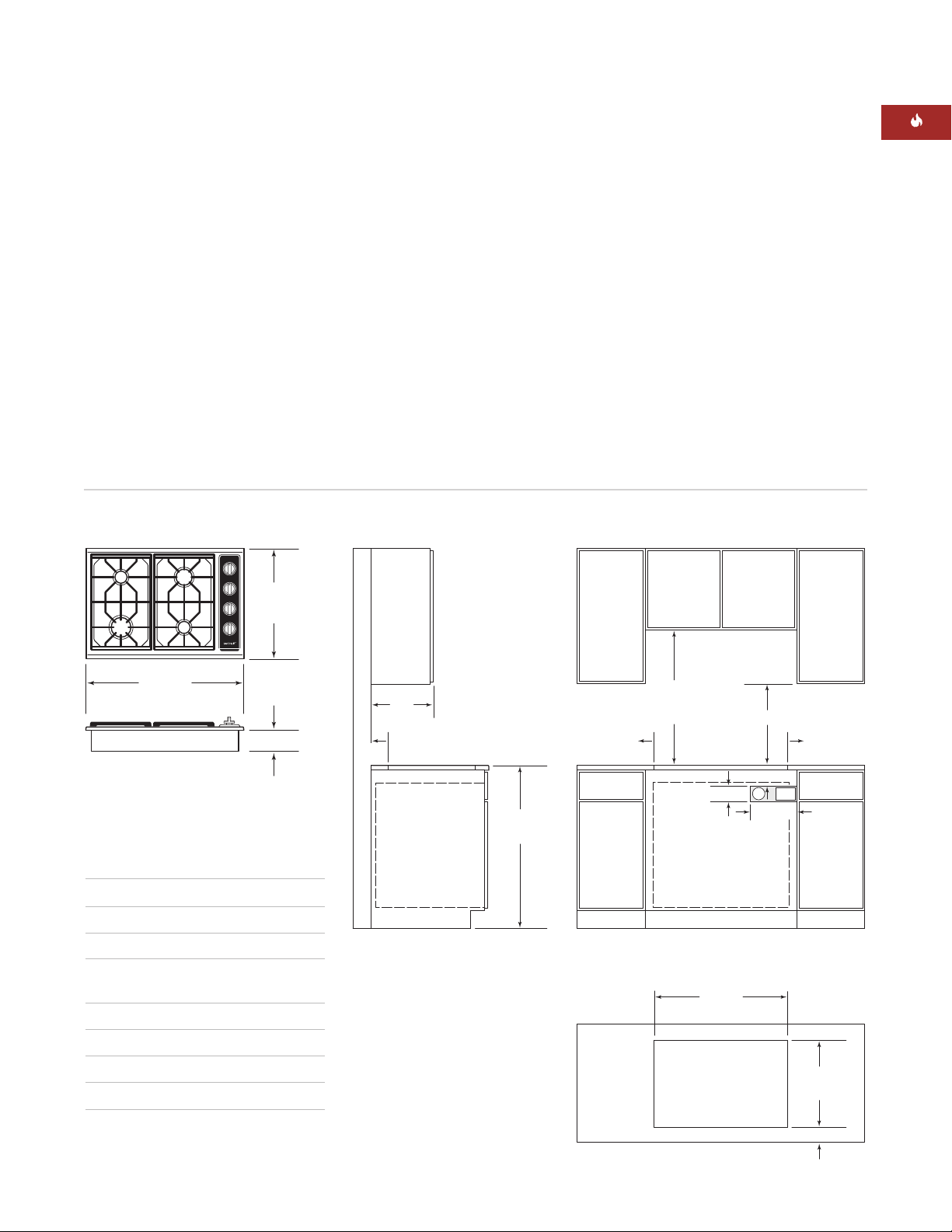
IN S TA LL AT I ON S P E C I F I C AT I O N S
The illustrations below provide the overall
dimensions, countertop cut-out and installation
specifications for Model ICBCT30G.
IMPORTANT NOTE:
838 mm wide cabinets are
recommended for installation of Model
ICBCT30G.
A Wolf 762 mm single built-in oven may be
If the Model ICBCT30G is installed above
cabinets, the gas and electrical placement is not
critical. A grounded outlet needs to be placed
within 1.2 m of the right rear of the cooktop.
IMPORTANT NOTE:
units are installed side by side, refer to the
countertop cut-out dimensions on page 11.
installed below Model ICBCT30G. For this
installation, unless you are using cabinets
deeper than 610 mm, it is recommended that
the electrical and gas supply be placed in the
base cabinet to the right of the oven. Refer to
installation instructions provided with the builtin oven for additional specifications.
I N S TA LL AT I O N SP E C IF I C AT I O N S – M O DE L I C BC T 3 0G
When multiple cooktop
Overall Dimensions
M O D E L I CB C T 30 G
D I M E N S I O N S
Overall Width 762 mm
Overall Height 102 mm
Overall Depth 533 mm
Recommended
Cabinet Width 838 mm
Minimum Cabinet Depth 578 mm
Minimum Height Clearance 102 mm
Cut-Out Width 737 mm
Cut-Out Depth 489 mm
Unit dimensions may vary to ±3 mm.
9
W O L F GAS C OO K TOP S
102 mm
E
G
457 mm min
914 mm
FLOOR TO
COUNTERTOP
762 mm min
COUNTERTOP
TO COMBUSTIBLE
MATERIALS
914 mm OVEN OPENING
254 mm
89 mm
SEE COUNTERTOP
CUT-OUT BELOW
889 mm
CUT-OUT WIDTH
COUNTERTOP CUT-OUT
FRONT
489 mm
CUT-OUT
DEPTH
64 mm min
229 mm TO
COMBUSTIBLE
*
229 mm TO
COMBUSTIBLE
*
SIDE
CABINET
330 mm
m
ax
*Minimum clearance from cooktop cut-out to combustible materials up to 457 mm above countertop.
NOTE: Gas and electrical location applies only to installation with built-in oven.
64
mm*
533 mm
OVERALL
DEPTH
914 mm
OVER ALL WID TH
102 mm
IN S TA LL AT I ON S P E C I F I C AT I O N S
The illustrations below provide the overall
dimensions, countertop cut-out and installation
specifications for Model ICBCT36G.
IMPORTANT NOTE:
991 mm wide cabinets are
recommended for installation of Model
ICBCT36G.
A Wolf 914 mm built-in oven may be installed
below Model ICBCT36G. For this installation,
unless you are using cabinets deeper than 610
mm, it is recommended that the electrical and
gas supply be placed in the base cabinet to the
right of the oven. Refer to installation instructions provided with the built-in oven for additional specifications.
I N S TA LL AT I O N SP E C IF I C AT I O N S – M O DE L I C BC T 3 6G
If the Model ICBCT36G is installed above
cabinets, the gas and electrical placement is not
critical. A grounded outlet needs to be placed
within 1.2 m of the right rear of the cooktop.
When a 914 mm built-in oven is installed below
Model ICBCT36G, it is recommended that the
rough opening for the oven be 197 mm from
the floor to ease the use of the oven door.
IMPORTANT NOTE:
When multiple cooktop
units are installed side by side, refer to the
countertop cut-out dimensions on page 11.
Overall Dimensions
M O D E L I CB C T 36 G
D I M E N S I O N S
Overall Width 914 mm
Overall Height 102 mm
Overall Depth 533 mm
Recommended
Cabinet Width 991 mm
Minimum Cabinet Depth 578 mm
Minimum Height Clearance 102 mm
Cut-Out Width 889 mm
Cut-Out Depth 489 mm
Unit dimensions may vary to ±3 mm.
10
IN S TA LL AT I ON I N S T R U C T I O N S
64 mm
min
FRONT OF COUNTERTOP
489 mm
CUT-OUT
DEPTH
743 mm
TWO MODULES WIDTH
1130 mm – THREE MODULES WIDTH OR
1124 mm – 762 mm COOKTOP AND ONE MODULE
1518 mm – FOUR MODULES WIDTH OR
1511 mm – 762 mm COOKTOP AND TWO MODULES OR
1276 mm – 914 mm COOKTOP AND ONE MODULE
356 mm
CUT-OUT
WIDTH
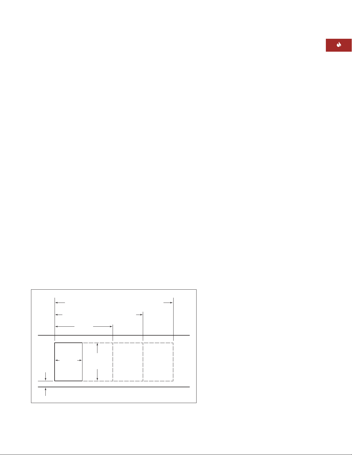
IN S TA LL AT I ON O P T I O N S
M U LT I P LE C O O K TO P I N S TA LL AT I O N
If the gas cooktop is to be used with any
combination of additional cooktop units or
modules with a filler strip, the cut-out width is
calculated by adding the corresponding units'
cut-out dimensions plus 32 mm for each additional unit. Refer to the illustration below.
P T I O N A L
O
I N S TA LL AT I O N S
IMPORTANT NOTE:
When multiple units are
installed side by side, each unit must have its
own separate recommended electrical circuit.
When two or more modules are installed
together, an integrated module filler strip
(IFILLER/S) is recommended. Contact your
Wolf dealer for information on these accessory
components.
Dimensions will
vary according to
the specific installation.
Countertop cut-out dimensions for installation of multiple cooktops
11

M P O RTA N T
I
N O T E
This installation
must conform with
local codes and
ordinances.
W O L F GAS C OO K TOP S
GA S S U PP LY R E Q U I R E M E NT S
EXPLOSION HAZARD—
Securely tighten all external gas
connections.
Failure to do so can result in explosion,
fire or death.
IMPORTANT NOTE:
The gas cooktop must be
connected to a regulated gas supply.
IMPORTANT NOTE:
This installation must
conform with local codes and ordinances.
IMPORTANT NOTE:
The natural gas cooktop
is rated for elevations up to 2438 m without
adjustment. Install a high altitude kit for elevations from 2438 to 3084 m. The LP gas cooktop
is rated for 3084 m.
The rating plate, located on the underside of
the burner box, has information on the type of
gas that should be used. If this information
does not agree with the type of gas available,
check with the local gas supplier.
Provide a gas supply line of 19 mm rigid pipe
to the cooktop location. A smaller size pipe on
long runs may result in insufficient gas supply.
Pipe joint compounds, suitable for use with LP
gas should be used. For LP gas, piping or
tubing size can be 13 mm minimum. LP gas
suppliers usually determine the size and materials used on the system.
If local codes permit, a flexible metal appliance
connector is recommended for connecting this
cooktop to the gas supply line. Do not kink or
damage the flexible connector when moving
the cooktop. You will need to determine the
fittings required, depending on the size of your
gas supply line, flexible metal connector and
shut-off valve.
If rigid pipe is used as a gas supply line, a
combination of pipe fittings must be used to
obtain an in-line connection to the cooktop. All
strains must be removed from the supply and
gas lines so the cooktop will be level and in
line.
12
GA S R AT I N G
Total Heat Electrical Types and
Output Gas Rating Appliance Pressures
Model # (Gas) Units (Watts) Category (mbar) Country of Destination
I2H G20 at 20
ICBCT15G/S 6.8 kW 230
ICBCT15G/S-LP 494 g/h 230 I3P G31 at 37
ICBCT30G/S 14.7 kW 230
ICBCT30G/S-LP 1069 g/h 230 I3P G31 at 37
ICBCT36G/S 17.7 kW 230
ICBCT36G/S-LP 1287 g/h 230 I3P G31 at 37
I2E G20 at 20 DE, PL
I2E+ G20 at 20/25 BE, FR
I2H G20 at 20
I2E G20 at 20 DE, PL
I2E+ G20 at 20/25 BE, FR
I2H G20 at 20
I2E G20 at 20 DE, PL
I2E+ G20 at 20/25 BE, FR
AT, DK, EE, FI, GR, IE, IT, LT,
NO, PT, ES, SE, SI, SK, GB, CH
BE, CZ, FR, GR, IE, NL, NO, PT,
ES, GB, CH
AT, DK, EE, FI, GR, IE, IT, LT,
NO, PT, ES, SE, SI, SK, GB, CH
BE, CZ, FR, GR, IE, NL, NO, PT,
ES, GB, CH
AT, DK, EE, FI, GR, IE, IT, LT,
NO, PT, ES, SE, SI, SK, GB, CH
BE, CZ, FR, GR, IE, NL, NO, PT,
ES, GB, CH

IN S TA LL AT I ON I N S T R U C T I O N S
EL E CT R I C AL RE Q U IR E M E N T S
ELECTRICAL SHOCK HAZARD—
Plug into a grounded 3-prong adapter.
Do not remove ground prong.
o not use an adapter.
D
Failure to follow these instructions can
result in electric shock, fire or death.
IMPORTANT NOTE:
If codes permit and a
separate ground wire is used, it is recommended that a qualified electrician determine
that the ground path is adequate.
IMPORTANT NOTE:
Check with a qualified
electrician if you are not sure whether the
cooktop is properly grounded.
IMPORTANT NOTE:
Do not ground to a gas
pipe.
A 220-240 VAC, 50/60 Hz, fused electrical
supply is required. A time-delay fuse or circuit
breaker is recommended. It is recommended
that a separate circuit serving only this appliance be provided.
Electronic ignition systems operate within
wide voltage limits, but proper ground and
polarity are necessary. In addition to checking
that the outlet provides 220-240 VAC power
and is correctly grounded, the outlet must be
checked by a qualified electrician to see if it is
wired with correct polarity. A wiring diagram is
provided in the literature package.
IMPORTANT NOTE:
Connection of this appliance should be through a fused connection
unit or a suitable isolator, which complies with
national and local safety regulations. The
on/off switch should be easily accessible after
the appliance has been installed. If the switch
is not accessible after installation (depending
on country) an additional means of disconnection must be provided for all poles of the
power supply. When switched off there must
be an all pole contact gap of 3 mm in the
isolator switch. This 3 mm contact disconnect
gap must apply to any isolator switch, fuses
and/or relays according to EN60335.
R E C O M M E N D E D GR O U N D M ET H O D
IMPORTANT NOTE:
For your personal safety,
this cooktop must be grounded. This cooktop
is equipped with a 3-prong ground plug. To
minimize possible shock hazard, a 85C
minimum rated cord must be plugged into a
mating 3-prong ground-type outlet, grounded
in conformance with all local codes and ordinances. If a mating outlet is not available, it is
the obligation of the customer to have a
properly grounded, 3-prong outlet installed by
a qualified electrician.
IMPORTANT NOTE:
If product is connected to
a GFCI protected outlet, nuisance tripping of
power supply may occur, resulting in loss of
product operation.
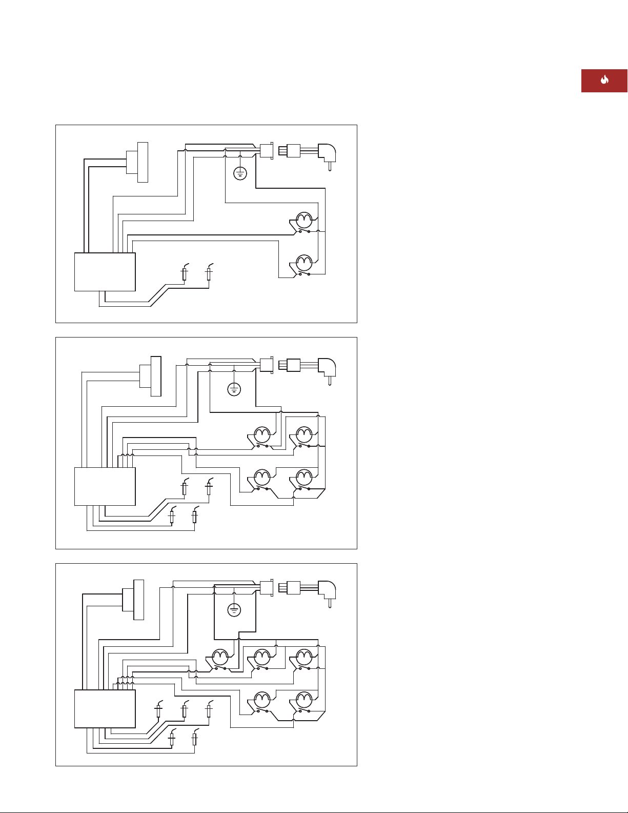
W I R I N G D IA GR A M
This appliance, when installed, must be electrically grounded in accordance with local codes.
A wiring diagram covering the control circuit
for each Wolf gas cooktop model can be found
on page 17.
13
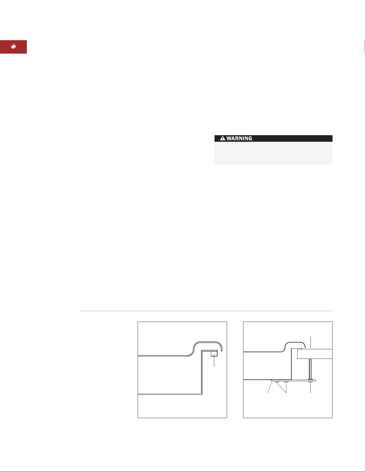
Cooktop
Burner Box
Foam
Strip
W O L F GAS C OO K TOP S
89 mm
Clamping
Screw
Burner Box
Countertop
Bracket
Screws
Bracket
C O O K T O P IN S TA L LATI O N
Remove the cooktop, burner grates and burner
caps from the shipping package.
Lower the cooktop into the countertop cut-out
opening. Center the cooktop in the opening
and check that the front edge of cooktop is
parallel to the front edge of the countertop.
Check that all required clearances are met. Use
a pencil to outline the rear edge of the cooktop
on the countertop. Remove the cooktop from
the countertop opening.
IMPORTANT NOTE:
When repositioning the
cooktop in the countertop cut-out opening, lift
the entire cooktop up from the opening to
prevent scratching the countertop.
Remove the foam strip from the hardware
package. Apply the foam strip around the
bottom of the burner box flush with the edge
as shown in the illustration below.
Reinsert the cooktop into the countertop
opening. Check that the cooktop is parallel to
the front edge of the countertop. Lift the entire
cooktop to make adjustments and align the
rear edge with the pencil line.
G A S L E A K T E S TI N G
Use a brush and liquid detergent to test all gas
connections for leaks. Bubbles around connections will indicate a leak. If a leak appears, shut
off gas valve controls and adjust connections.
Then check connections again. Clean all the
detergent solution from the cooktop.
Never test for a gas leak with a match or
other flame.
Attach the brackets to the burner box. Insert
the 89 mm clamping screws into the brackets.
Use a screwdriver to tighten the clamping
screws against the underside of the countertop. Refer to the illustration below. Do not
overtighten screws.
Foam strip application
Bracket installation
14
IN S TA LL AT I ON I N S T R U C T I O N S
SU R FAC E B U RN E R S
I N I T I A L LI G H TI N G
The surface burners use electronic igniters in
place of standing pilots. When the cooktop
control knob is pushed in and turned to the
position, the system creates a spark to
light the burner. This sparking continues until
the electronic ignition senses a flame. If the
burner fails to ignite after 10 seconds, return
the knob to the position and attempt to
ignite by turning the knob back to the
position.
Be sure to place the burner heads and caps on
each burner base and position the burner
grates over the burner bases and heads before
lighting.
To check operation of the surface burners,
push in and turn each control knob to the
position. The flame should light within four
seconds.
If the burners do not light properly, turn
control knob to the position. Check that
the burner heads and caps are in the proper
position. Check that the power supply cord is
plugged in and that the circuit breaker or
house fuse has not blown. Check operation
again, if the burners do not light properly at
this point, contact a Wolf authorized service
center.
IMPORTANT NOTE:
Initial lighting of the
surface burners may take slightly longer, as air
in the system must be purged before gas can
be supplied to the burner.
CO O KTO P R E MO VA L
If it is necessary to remove the cooktop for
cleaning or service, shut off the gas supply.
Disconnect the gas and electric supply.
Remove the mounting brackets on the right
and left side of the burner box and remove the
cooktop. Reinstall in the reverse order and
check the gas connection for leaks.
TR O U BL ES H O OT I N G
IMPORTANT NOTE:
If the cooktop does not
operate properly, follow these troubleshooting
steps:
Verify that power is being supplied to the
cooktop.
Check that gas valves are turned to the ON
position.
Check the gas supply and electrical
connections to ensure that the installation
has been completed correctly.
Follow troubleshooting procedures as
described in the Wolf Gas Cooktops
Use & Care Information.
If the cooktop still does not work, contact
a Wolf authorized service center. Do not
attempt to repair the cooktop yourself. Wolf
is not responsible for service required to
correct a faulty installation.
15

W O L F GAS C OO K TOP S
I F Y O U N EE D SE RVI C E
For service in your area, contact either your
Wolf dealer or visit the Showroom Locator
section of our website, wolfappliance.com
to find the regional distributor by country.
C O N TA C T
I N F O R M A T IO N
Website:
wolfappliance.com
When calling for service, you will need the
cooktop model and serial numbers. Both
numbers are listed on the rating plate,
located on the underside of the cooktop.
Refer to the illustration on page 6 for
location of the rating plate.
16
The information and images in this book are the
copyright property of Wolf Appliance, Inc., an affiliate of Sub-Zero, Inc. Neither this book nor any
information or images contained herein may be
copied or used in whole or in part without the
express written permission of Wolf Appliance,
Inc.,an affiliate of Sub-Zero, Inc.
©Wolf Appliance, Inc. all rights reserved.
IN S TA LL AT I ON I N S T R U C T I O N S
P
OWER CORD
FRONT
R
IV
GAS VALVE
RED
RED
B
LACK
WHITE
G
RN/YEL
B
LACK
REAR
BLACK
BLACK
WHITE
WHITE
POWER CORD
WHITE
RIGHT
FRONT
BLACK
RIV
GAS VALVE
RED
RED
RED
RED
WHITE
GRN/YEL
B
LACK
RIGHT
REAR
LEFT
REAR
LEFT FRONT
B
LACK
WHITE
WHITE
BLACK
LEFT FRONT
POWER CORD
RED
RIV
GAS VALVE
WHITE
BLACK
RIGHT
REAR
LEFT REAR
RIGHT
FRONT
CTR REAR
GRN/YEL
BLACK
RED
RED
RED
BLACK
WHITE
WI R IN G D I AG RA M S
Model ICBCT15G
Model ICBCT30G
Model ICBCT36G
17

PRECAUCIÓN
I NF O R M A C I Ó N
D E C O NTA C TO
ágina Web:
P
www.sub-
ero.eu.com
z
Cuando consulte las instrucciones que aparecen en
esta guía, encontrará símbolos de ADVERTENCIA y
PRECAUCIÓN. Esta información en recuadros es
importante para instalar el equipo de Wolf de forma
segura y eficaz. Existen dos tipos de posibles riesgos
que pueden producirse durante una instalación.
WOLF®es una marca comercial registrada de Wolf Appliance, Inc.
indica una situación en la que se pueden sufrir
heridas leves o provocar daños secundarios al
producto si no se siguen las instrucciones.
indica peligro de que se produzcan heridas
personales graves o incluso puede provocar
la muerte si no se siguen las precauciones
especificadas.
Otro tipo de anotación que es importante resaltar es
la que se incluye en NOTA IMPORTANTE: En esta
nota se resalta la información que resulta especialmente importante para que la instalación se realice
sin problemas.
PL ACA S DE G A S DE W O LF
R EQ U I S I TO S DE IN STA LA C IÓ N
QUÉ SE DEBE HACER SI HUELE A GAS:
Este aparato debe instalarse de
acuerdo con las normativas vigentes
y sólo puede ser utilizado en un
lugar que esté bien ventilado. Lea las
instrucciones antes de instalar o
utilizar este aparato.
NOTA IMPORTANTE:
La instalación y el mantenimiento
deben ser realizados por un insta-lador
cualificado, por un centro de asistencia
técnica o por el proveedor de gas.
No almacene ni utilice gasolina ni otros
vapores ni líquidos infla-mables cerca
de éste o de otros aparatos.
La utilización de un aparato de cocción
de gas produce calor y vaho en la
habitación en la que está instalado.
Asegúrese que la cocina está bien ventilada; mantenga despejados los agujeros
de ventilación natural o instale un
dispositivo de ventilación mecánico
(campana extractora mecánica).
No encienda ningún aparato.
No toque ningún interruptor eléctrico.
No utilice ningún teléfono dentro
del edificio.
Llame inmediatamente a su proveedor
de gas desde el teléfono de un vecino.
Siga las instrucciones que le proporcione el proveedor de gas.
Si no le es posible ponerse en
contacto con el proveedor de gas,
llame a los bomberos.
Si utiliza mucho el aparato y lo hace de
manera prolongada, es posible que
necesite ventilación adicional, por
ejemplo, puede abrir una ventana, o si
quiere que la ventilación sea más eficaz,
aumente el nivel de la ventilación
mecánica, si dispone de ella.
19
PL ACA S DE G A S DE W O LF
I N FO RM AC I Ó N
D E L A P L A C A
D E DAT O S
Referencia del
odelo
m
úmero de serie
N
R EQ U I S I TO S DE IN STA LA C IÓ N
NOTA IMPORTANTE: Esta instalación debe ser
realizada por un instalador cualificado, por un
centro de asistencia técnica o por el proveedor
de gas.
NOTA IMPORTANTE:
Guarde estas instrucciones
de instalación para que el inspector local pueda
utilizarlas.
Lea las instrucciones de instalación antes de
llevar a cabo la instalación.
Instalador:
guarde estas instrucciones para que
el inspector local pueda utilizarlas como referencia y, a continuación, entréguelas el propietario
del aparato.
Propietario:
lea y guarde estas instrucciones
para que pueda utilizarlas como referencia en el
futuro y asegúrese de leer la guía de uso y
manteni-miento antes de utilizar el aparato.
NOTA IMPORTANTE:
Este aparato debe instalarse
siguiendo las normativas nacionales correspondientes. Se debe aplicar al aparato el voltaje, la
frecuencia y el amperaje adecuados desde una instalación eléctrica resistente con toma de tierra protegida por un fusible de retardo. El voltaje, la frecuencia y el amperaje se muestran en la placa de datos
del producto.
Apunte la referencia del modelo y el número de
serie antes de instalar el aparato. Esta información
se muestra en la placa de datos del producto situada
en la parte inferior de la placa. Observe la siguiente
ilustración.
AN TE S DE C OM E N Z A R
Es responsabilidad del propietario asegurarse de
que la instalación se realiza de manera correcta.
Esta placa debe ser instalada por un técnico cualificado. Debe asegurarse de que la instalación
eléctrica es la correcta y que cumple todos los
códigos y normativas nacionales.
Antes de llevar a cabo la instalación, asegúrese
de que las condiciones de distribución locales
(tipo y presión del gas) y el ajuste del aparato
son compatibles.
Debe disponer de una entrada de suministro de
gas; consulte la sección Requisitos del suministro
de gas en la página 26. También debe disponer de
una conexión eléctrica a tierra; consulte la sección
Requisitos eléctricos en la página 27.
Las condiciones de ajuste de este aparato se
especifican en la etiqueta (o en la placa de datos
del producto). La placa de datos está ubicada en
la parte inferior del aparato.
20
Ubicación de la placa
de datos debajo
de la placa
Ubicación de la placa de datos

I NS T R U C C I ON E S DE IN STA LA C IÓ N
AN TE S DE C OM E N Z A R
Inspeccione el lugar en el que va a instalar la
placa. El lugar en el que va a instalarla debe estar
alejado de áreas en las que pueda haber corrientes fuertes, por ejemplo, ventanas, puertas
y salidas de aire caliente o ventiladores. No
debe obstruir el flujo de combustión ni el aire
de ventilación.
Este aparato no está conectado a ningún dispositivo de evacuación de productos de combustión.
El aparato debe ser instalado y conectado siguiendo las normativas de instalación vigentes.
Debe prestar especial atención a los requisitos
relevantes correspondientes a la ventilación.
Esta placa está diseñada para que se utilice en
spacios interiores.
e
P RE PA R A C I ÓN D EL SI TI O
D IM E N S I ON E S DE C ORT E D E
L A E N CI M E R A
NOTA IMPORTANTE:
Se deben utilizar las medidas
de las cavidades de la encimera que se muestran en
la página siguiente. Las medidas que se especifican
mantienen los espacios requeridos.
Esta placa está diseñada para que se adapte a un
armario de base estándar de 610 mm de fondo con
una encimera de 635 mm de fondo. Antes de cortar
la encimera, compruebe que la placa va a quedar
separada de las paredes laterales del armario
inferior. Deberá dejar al menos una distancia de
140 mm entre la encimera y cualquier superficie
combustible que esté justo debajo de la unidad.
NOTA IMPORTANTE:
No selle la placa a la
encimera. Es posible que necesite quitarla para
realizar alguna tarea de mantenimiento.
R EQ U I S I TO S DE UB I C A C I ÓN
Las ilustraciones que se incluyen en las páginas
siguientes proporcionan las medidas totales, las
medidas del corte de la encimera y las especificaciones de la instalación de las placas de gas de Wolf.
Mantenga las siguientes medidas de instalación
mínimas:
Distancia horizontal mínima desde los lados y la
parte trasera del corte de la encimera a material
combustible vertical adyacente, extendiéndose
un mínimo de 457 mm por encima de la
encimera, de la siguiente manera: 178 mm
desde los bordes laterales de la cavidad para la
placa de 381 mm; 229 mm desde los bordes
laterales de la cavidad para las placas de 762 mm
y 914 mm; 64 mm para el borde trasero de la
cavidad.
La distancia vertical mínima entre la encimera y
los materiales combustibles situados por encima
de la placa debe ser de 762 mm.
El fondo máximo de los armarios superiores
laterales situados por encima de la placa debe
ser de 330 mm con una distancia lateral mínima.
NOTA IMPORTANTE:
Cuando instale una campana
extractora, consulte los requisitos específicos de la
campana para obtener las medidas mínimas que
debe mantener respecto a la encimera.
Si no coloca la placa siguiendo las distancias
de separación correctas, es posible que se
produzca un incendio.
21
914 mm
DEL SUELO A
LA ENCIMERA
762 mm mín.
ENCIMERA HASTA
LOS MATERIALES
INFLAMABLES
CONSULTAR CORTE DE
LA ENCIMERA A CONT.
356 mm
ANCHO DE
CORTE
CORTE DE LA ENCIMERA
FRONTAL
489 mm
FONDO DE
CORTE
64 mm mín.
178 mm HASTA
LOS MATERIALES
INFLAMABLES*
178 mm HASTA
LOS MATERIALES
INFLAMABLES*
ARMARIO
LATERAL
330 mm
máx.
*Espacio de separación mínimo desde el corte de la superficie de cocción hasta los materiales inflamables hasta un máximo
de 457 mm sobre la encimera.
NOTA: la instalación detallada permite montar dos módulos de 381 mm contiguos.
E
381 mm
381
mm
102 mm
457 mm mín.
127
mm
LA UBICACIÓN DE LA TOMA
ELÉCTRICA Y DE GAS SE
EXTIENDE EN EL SUELO
G
64
mm*
PL ACA S DE G A S DE W O L F
381 mm
ANCHURA TOTAL
5
33 mm
FONDO
T
OTAL
102 mm
E SP E C I F IC AC I O N ES D E L A INS TA L AC I ÓN
Las ilustraciones que se muestran a continuación
proporcionan las medidas totales, las medidas de
corte de la encimera y las especificaciones de instalación que corresponden al modelo ICBCT15G.
Para el modelo ICBCT15G, el servicio de gas debe
suministrarse a través del suelo si la placa no se ha
instalado encima de un horno. Consulte la ilustración
para obtener información específica sobre la colocación de la toma de gas y de electricidad.
E SP E C I F IC AC I O N ES D E L A I N S TA LA CI Ó N – MO D E L O I C B CT 1 5 G
NOTA IMPORTANTE:
Cuando instale varias placas
juntas, consulte las dimensiones de corte de la
encimera en la página 25.
Medidas totales
M OD E L O I C B C T1 5 G
M ED I D AS
Anchura total 381 mm
Altura total 102 mm
Fondo total 533 mm
Anchura del armario
recomendada 838 mm
Fondo mínimo del armario 578 mm
Espacio mínimo de altura 102 mm
Ancho del corte 356 mm
Fondo del corte 489 mm
Las dimensiones de la unidad pueden
variar ±3 mm.
22
457 mm mín.
914 mm
DEL SUELO A
LA ENCIMERA
762 mm mín.
ENCIMERA HASTA
L
OS MATERIALES
INFLAMABLES
762 mm APERTURA DEL HORNO
102 mm
254 mm
89 mm
E
CONSULTAR CORTE DE
LA ENCIMERA A CONT.
229 mm HASTA
LOS MATERIALES
INFLAMABLES
*
229 mm HASTA
LOS MATERIALES
INFLAMABLES
*
64
mm*
ARMARIO
LATERAL
330 mm
máx.
737 mm
ANCHO DE CORTE
CORTE DE LA ENCIMERA
PARTE DELANTERA
489 mm
FONDO
DE CORTE
64 mm mín.
*Espacio de separación mínimo desde el corte de la superficie de cocción hasta los materiales inflamables hasta un máximo
de 457 mm sobre la encimera.
NOTA: la instalación detallada permite montar dos módulos de 381 mm contiguos.
G
I NS T R U C C I ON E S DE L A IN S TALAC IÓ N
5
33 mm
FONDO
TOTAL
762 mm
ANCHURA TOTAL
102 mm
E SP E C I F IC AC I O N ES D E L A INS TA L AC I ÓN
Las ilustraciones que se muestran a continuación
proporcionan las medidas totales, las medidas de
corte de la encimera y las especificaciones de instalación que corresponden al modelo ICBCT30G.
NOTA IMPORTANTE:
Para la instalación del modelo
ICBCT30G se recomienda utilizar armarios con un
ancho de 838 mm.
Se puede instalar un horno integrable sencillo de
Si instala el modelo ICBCT30G encima de los
armarios, la colocación de la toma eléctrica y de gas
no es importante. Es necesario colocar una toma de
corriente conectada a tierra a una distancia de 1,2 m
de la parte trasera derecha de la placa.
NOTA IMPORTANTE:
juntas, consulte las dimensiones de corte de la
encimera en la página 25.
762 mm debajo del modelo ICBCT30G. Para esta
instalación, a menos que vaya a utilizar armarios
con un fondo superior a 610 mm, se recomienda que
la toma eléctrica y de gas se coloque en un armario
base situado a la derecha del horno. Consulte las
instrucciones de instalación que se proporcionan con
el horno integrable para obtener más información.
E SP E C I F IC AC I O N ES D E L A I N S TA LA CI Ó N – MO D E L O I C B CT 3 0 G
Cuando instalen varias placas
Medidas totales
M OD E L O I C B C T3 0 G
M ED I D AS
Anchura total 762 mm
Altura total 102 mm
Fondo total 533 mm
Anchura del armario
recomendada 838 mm
Fondo mínimo del armario 578 mm
Espacio mínimo de altura 102 mm
Ancho del corte 737 mm
Fondo del corte 489 mm
Las dimensiones de la unidad pueden
variar ±3 mm.
23
 Loading...