

Wolf ICBCT15I/S Installation Instructions Manual

INDUCTION COOKTOPS
INSTALLATION INSTRUCTIONS
INSTRUCCIONES DE INSTALACIÓN
INSTRUCTIONS D’INSTALLATION
ISTRUZIONI PER L’INSTALLAZIONE
INSTALLATIONSANWEISUNGEN

2

ENGLISH 4
ESPÃNOL 21
FRANÇAIS 38
ITALIANO 55
DEUTSCH 72
3

CONTACT
INFORMATION
Website:
wolfappliance.com
As you follow these instructions, you will
notice WARNING and CAUTION symbols.
This blocked information is important for the
safe and efficient installation of Wolf equipment. There are two types of potential
hazards that may occur during installation.
WOLF®is a registered trademark of Wolf Appliance, Inc.
signals a situation where minor injury or
product damage may occur if you do not
follow instructions.
states a hazard that may cause serious
injury or death if precautions are not
followed.
Another footnote we would like to identify is
IMPORTANT NOTE: This highlights information that is especially relevant to a problemfree installation.
WOLF INDUCTION COOKTOPS
INSTALLATION REQUIREMENTS
IMPORTANT NOTE:
Save these Installation
Instructions for the local inspector’s use.
Please read the entire Installation Instructions prior to installation.
This installation must be completed by a
qualified technician.
Installer:
please retain these instructions
for local inspector’s reference, then leave
them with the homeowner.
Homeowner:
please read and keep these
instructions for future reference and be sure
to read the entire Use & Care Information
prior to use.
IMPORTANT NOTE:
This appliance must be
installed in accordance with local codes. The
correct voltage, frequency and amperage must
be supplied to the appliance from a dedicated,
grounded circuit which is protected by a
properly sized circuit breaker or time delay
fuse. The proper voltage, frequency, and
amperage ratings are listed on the product
rating plate.
BEFORE YO U S TART
Proper installation is your responsibility.
Have a qualified technician install this
cooktop. You must also assure that electrical installation is adequate and in compliance with all local codes and ordinances.
Installations and repairs must be performed
by a qualified or licensed contractor or
electrician qualified or licensed by the state,
province, or region where this appliance is
being installed.
Make sure you have everything necessary
for correct installation. It is the responsibility of the installer to comply with the installation clearances specified on the product
rating plate. The rating plate is located on
the underside of the cooktop.
Electrical ground is required; see Electrical
Requirements on pages 16–17.
This cooktop is intended for indoor use.
RATING PLATE
INFORMATION
Model Number
Serial Number
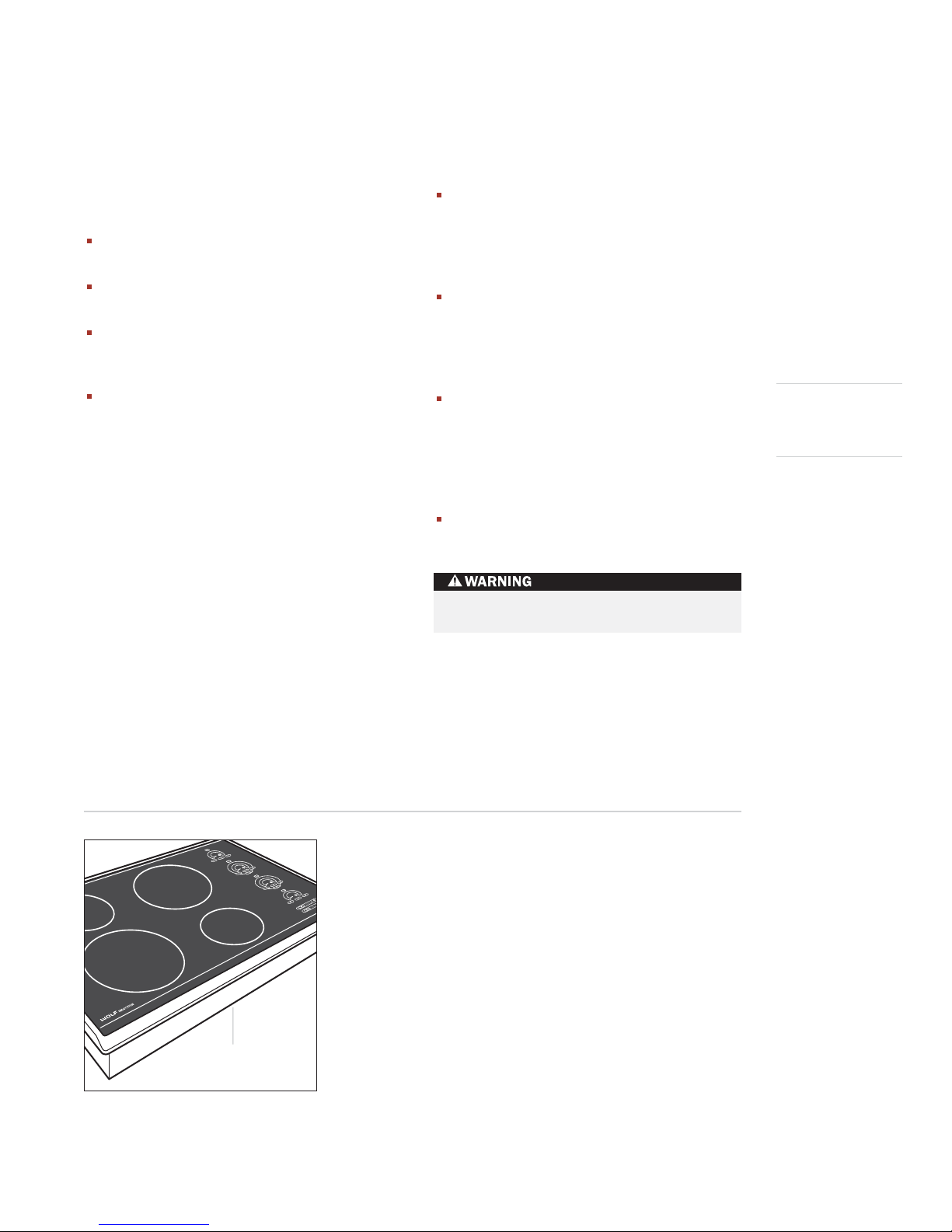
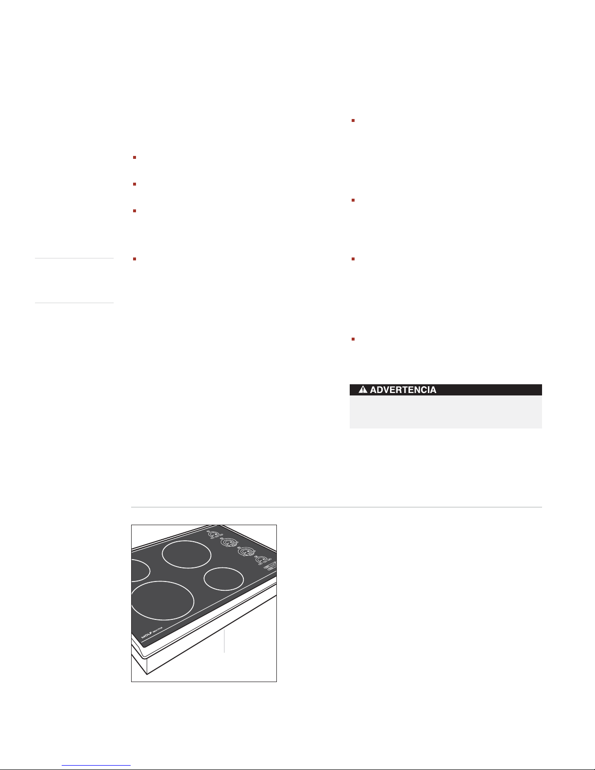
Record the model and serial numbers before
installing the cooktop. Both numbers are on
the rating plate, located on the underside of
the cooktop. Refer to the illustration below.
Location of rating
plate under cooktop
Rating plate location
5
WOLF INDUCTION COOKTOPS
SITE PREPARATION
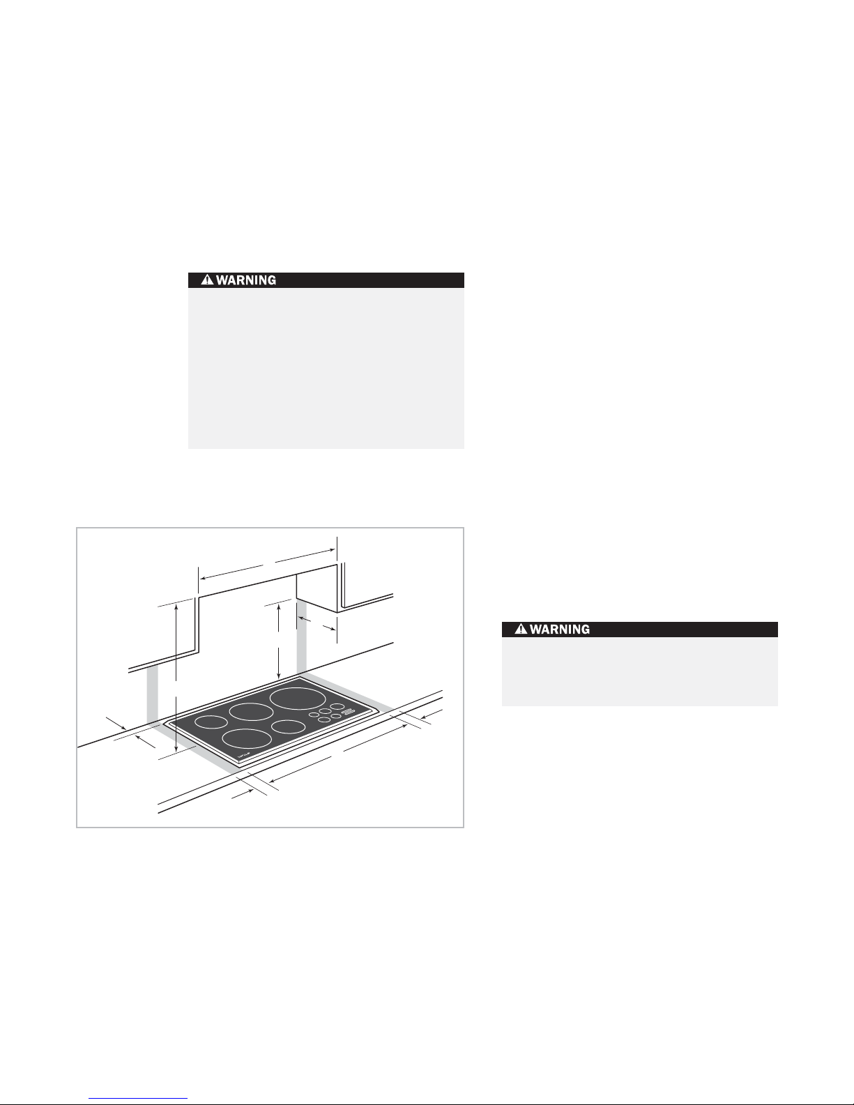
IMPORTANT NOTE:
Installation of the Wolf
induction cooktop must meet the following
location requirements. All dimensions listed
are minimum requirements for safe operation.
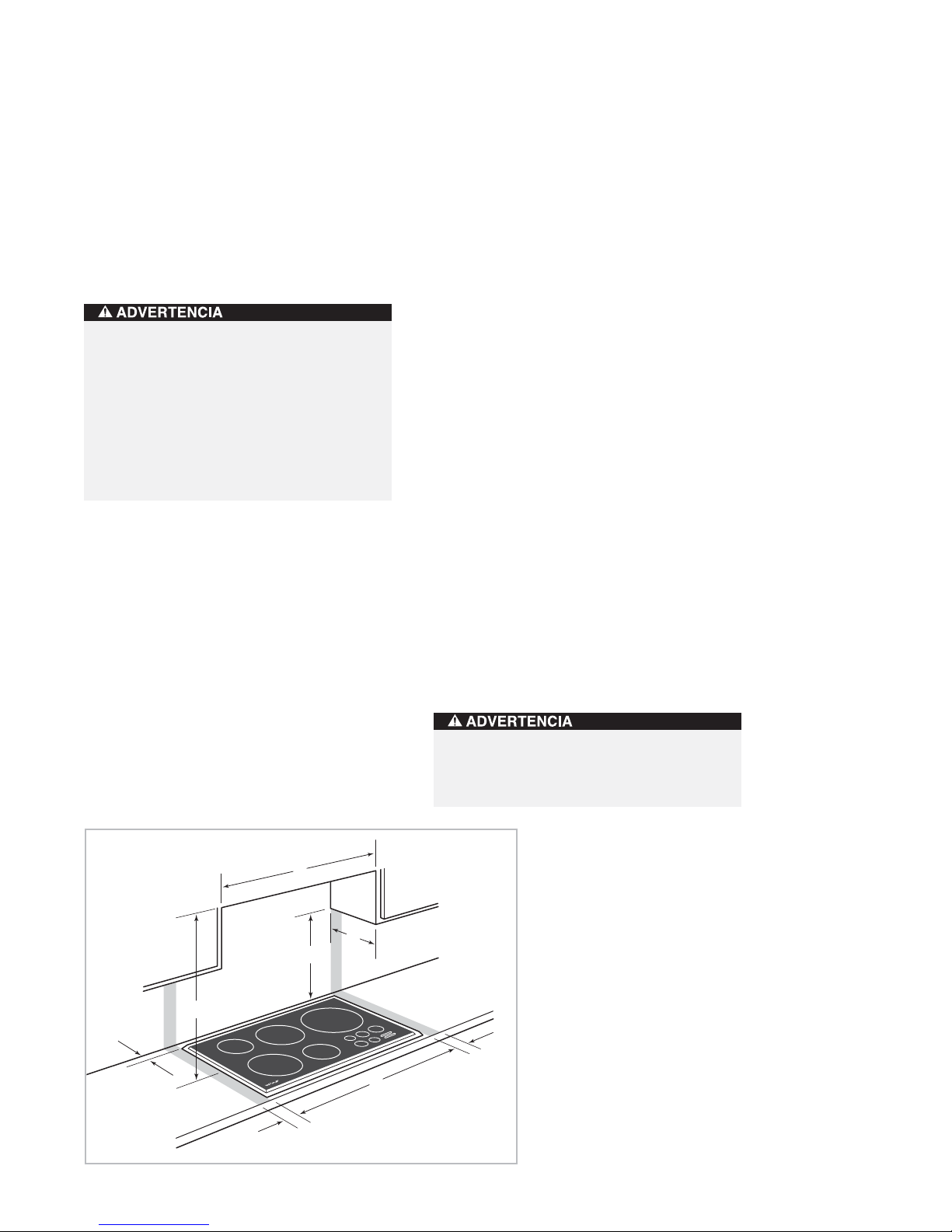
Refer to the illustration below.
To eliminate the risk of burns or fire by
reaching over heated surface units,
cabinet storage space located above the
surface units should be avoided. If
cabinet storage is to be provided, the risk
can be reduced by installing a ventilation
hood that projects horizontally a
minimum of 127 mm beyond the bottom
cabinets.
C
LOCATION IN COUNTERTOP
A)
Minimum flat countertop surface. Must be
equal to or greater than cooktop width.
B)
Minimum 25 mm wide clearance from the
cooktop side edge to any combustible
surface up to 457 mm above the cooktop
(noted by shaded area).
OVERHEAD CABINET DIMENSIONS
C)
Minimum spacing between overhead side
cabinets must be greater than or equal to
the nominal width of the cooktop unit(s).
D)
Minimum 457 mm vertical distance from
the countertop to the bottom of side
cabinets within minimum side clearance.
E)
Minimum vertical distance between the
countertop and combustible materials
above the cooktop must be 762 mm.
F)
Minimum 25 mm from rear wall.
G)
Maximum 330 mm depth of overhead and
side cabinets directly above and within side
clearance.
E
F
B
Minimum installation clearances
G
D
Failure to locate the cooktop without the
proper clearances will result in a fire
hazard.
B
A
6
INSTALLATION INSTRUCTIONS
INSTALLATION SPECIFICATIONS
The illustrations on pages 8–13 provide the
overall dimensions, installation specifications
and countertop cut-out for each of the Wolf
induction cooktop models.
These cooktops are designed to fit a standard
610 mm deep base cabinet with a 635 mm
deep countertop. Before making the countertop cut-out, verify that the cooktop will clear
the side walls of the base cabinet below.
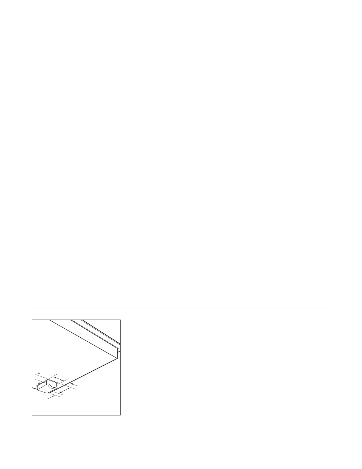
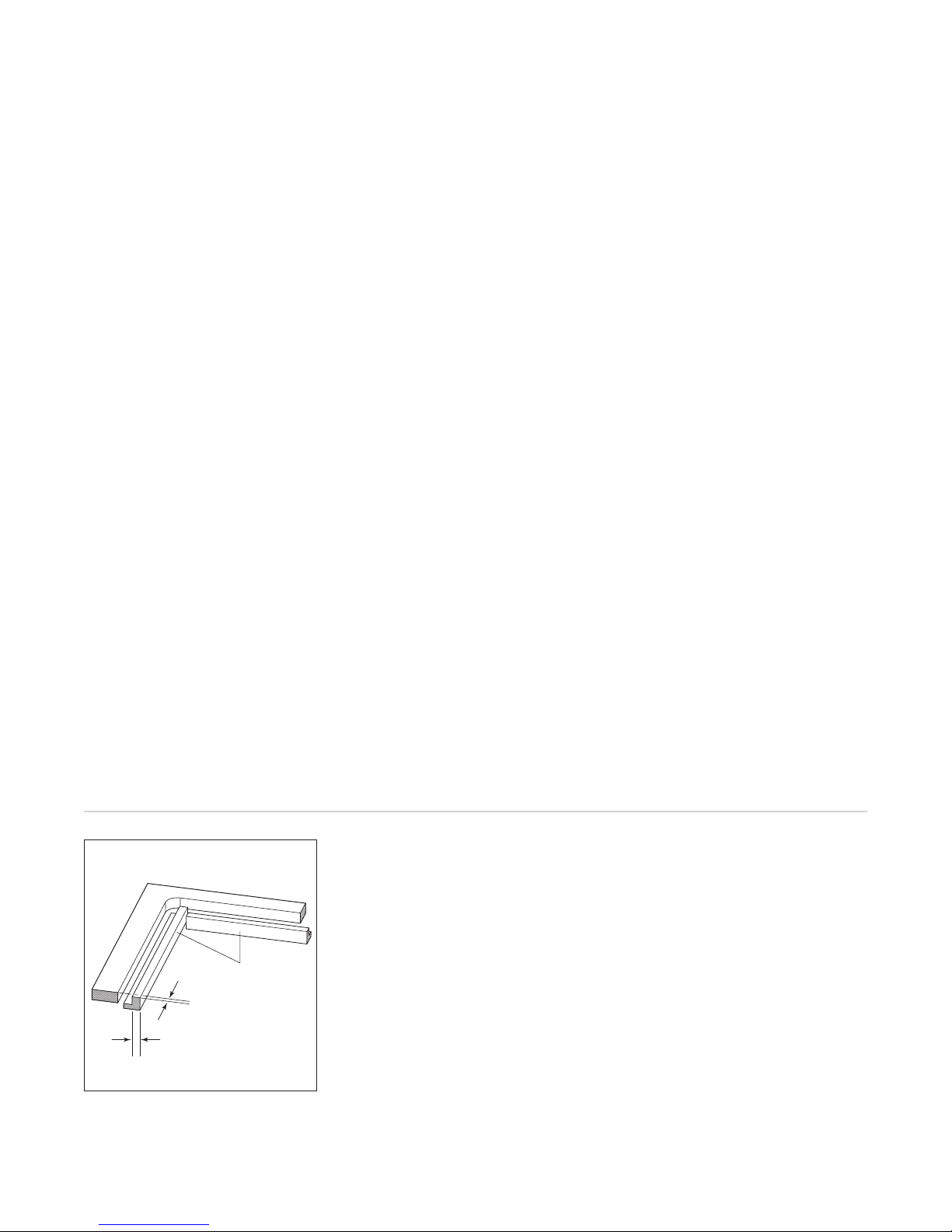
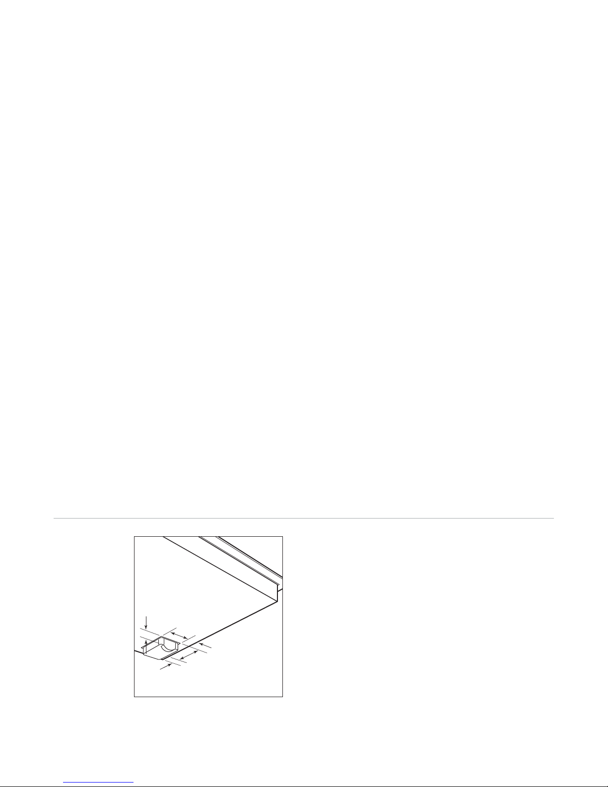
Clearance is required for the terminal block
located at the right rear of the cooktop. Refer
to the illustration below for dimensions.
FRAMED INDUCTION COOKTOPS
IMPORTANT NOTE:
A minimum height clearance of 152 mm is required between the countertop and any combustible surface directly
below the cooktop. This includes upper edges
of drawers located directly below unit. If a
shelf is installed below the unit, a 25 mm gap
at the rear of the cabinet shelf is necessary to
allow for proper ventilation. Failure to do so
could result in decreased performance or
product damage.
Wolf induction cooktops are designed to be
installed in combination with other cooktop
units.
IMPORTANT NOTE:
When multiple cooktops
and/or modules are installed side by side, refer
to countertop cut-out dimensions on page 11.
Wolf induction cooktops can accommodate a
Wolf downdraft ventilation system. Refer to
installation instructions provided with the
downdraft for additional specifications.
UNFRAMED INDUCTION COOKTOPS
IMPORTANT NOTE:
A minimum height clearance of 165 mm is required between the countertop and any combustible surface directly
below the cooktop. This includes upper edges
of drawers located directly below unit. If a
shelf is installed below the unit, a 25 mm gap
at the rear of the cabinet shelf is necessary to
allow for proper ventilation. Failure to do so
could result in decreased performance or
product damage.
IMPORTANT NOTE:
Unframed induction
cooktops are not designed to be installed in
combination with other cooktops.
IMPORTANT NOTE:
Unframed induction
cooktops cannot be installed with a downdraft
ventilation system.
For installation options of the unframed induction cooktops, refer to Unframed Installation
on pages 14–15.
32 mm
56
mm
22 mm
84
24
mm
Terminal block dimensions
mm
7
WOLF INDUCTION COOKTOPS
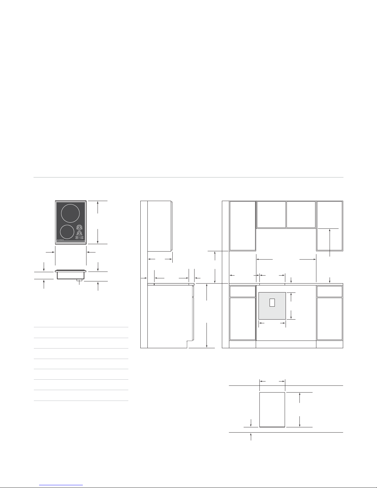
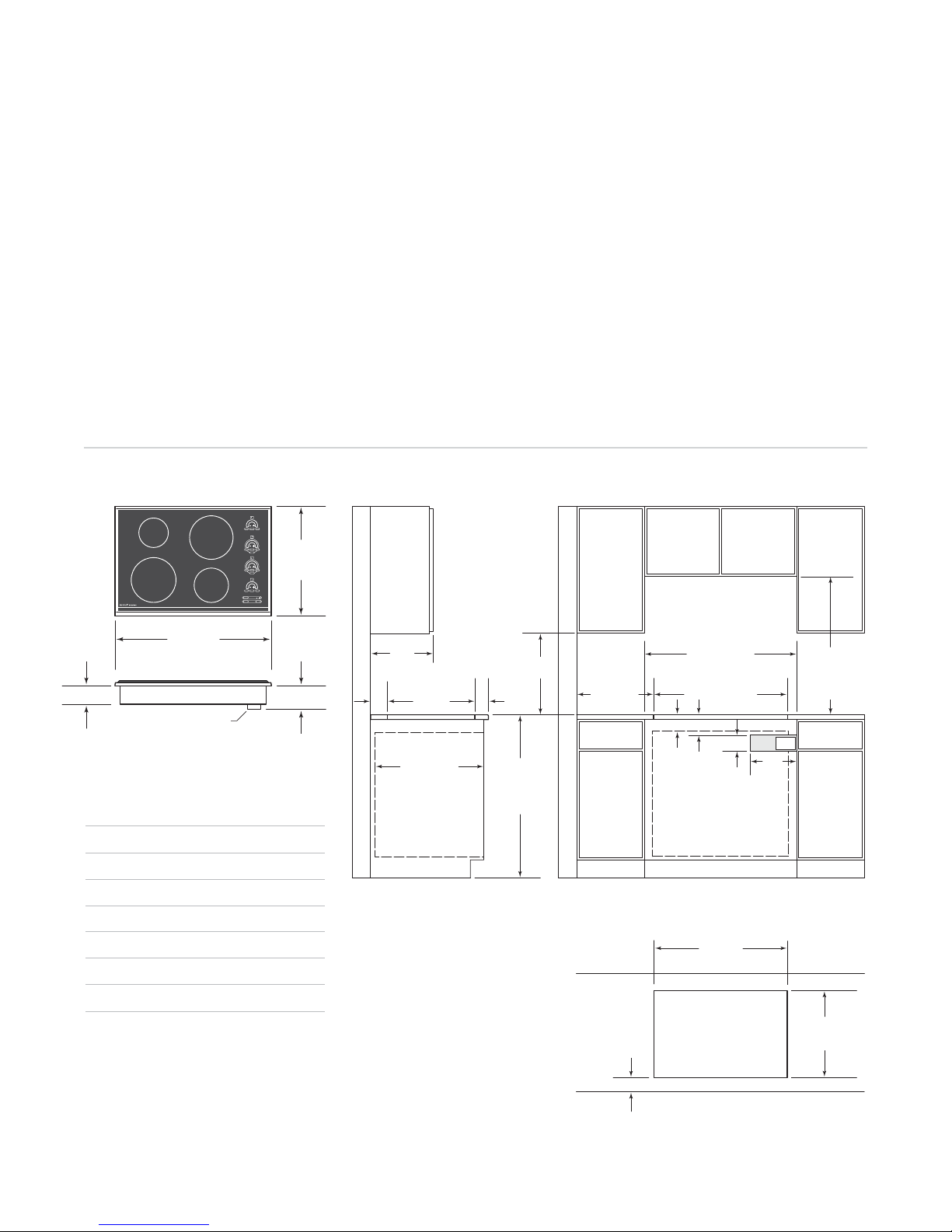
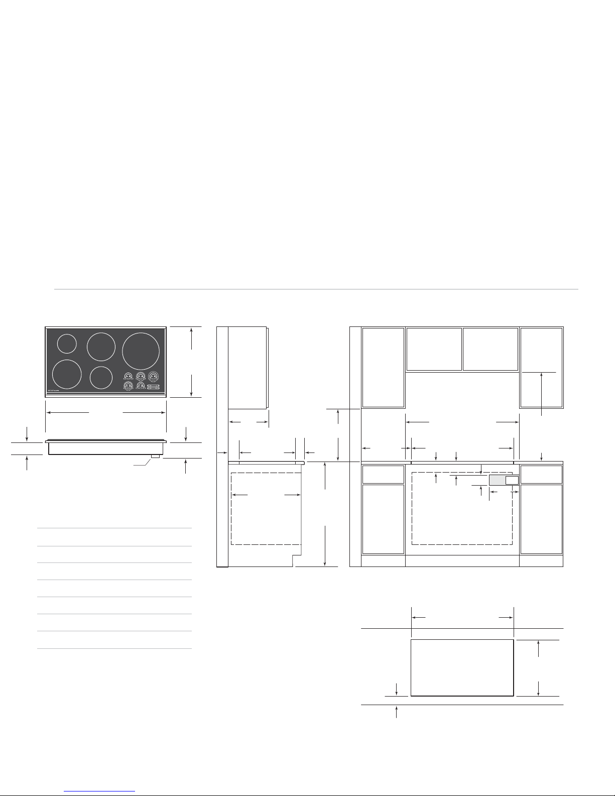
FRAMED MODEL ICBCT15I/S
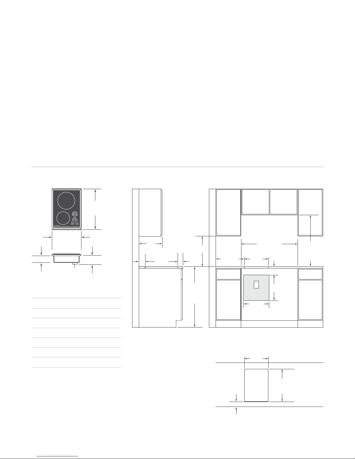
The illustrations below provide installation
specifications for Model ICBCT15I/S.
INSTALLATION SPECIFICATIONS – MODEL ICBCT15I/S
533 mm
OVERALL
DEPTH
381 mm
OVERALL WIDTH
89 mm
TERMINAL BOX
114 mm
Overall Dimensions
MODEL ICBCT15I/S
Overall Width 381 mm
Overall Height 89 mm
Overall Depth 533 mm
Minimum Cabinet Depth 578 mm
Minimum Height Clearance* 114 mm
Cut-Out Width 340 mm
Cut-Out Depth 489 mm
*Minimum 152 mm clearance is required
between countertop and any combustible
surface directly below the cooktop.
For detailed terminal block dimensions,
refer to the illustration on page 7.
Dimensions may vary to±3mm.
330 mm
max
51**
489 mm
mm
COOKTOP CUT-OUT
DEPTH
NOTE: Application shown allows for installation of two 381 mm modules side-by-side with 838 mm recommended cabinet width. 457 mm
recommended cabinet width for installation of single 381 mm cooktop or module. *Minimum clearance from both side edges of cooktop cut-out
to combustible materials up to 457 mm above countertop. **Minimum clearance from rear edge of cooktop cut-out to combustible mater ials up
to 457 mm above countertop.
64 mm
min
914 mm
STANDARD
FLOOR TO
COUNTERTOP
HEIGHT
Countertop Cut-Out
If Model ICBCT15I/S is installed above
cabinets, the electrical placement is not critical.
The appliance shall be installed in such a way
to allow disconnection of the appliance from
the supply mains after installation.
838 mm
RECOMMENDED
457
mm
min
51 mm*
CUT-OUT TO
COMBUSTIBLE
MATERIALS
(BOTH SIDES)
64 mm
min
CABINET WIDTH
340 mm
COOKTOP CUT-OUT
WIDTH
E
381 mm
340 mm
COOKTOP CUT-OUT
WIDTH
FRONT OF COUNTERTOP
114 mm
381
mm
489 mm
COOKTOP
CUT-OUT DEPTH
COUNTERTOP TO
COMBUSTIBLE
MATERIALS
ABOVE COOKTOP
762 mm
8
INSTALLATION INSTRUCTIONS
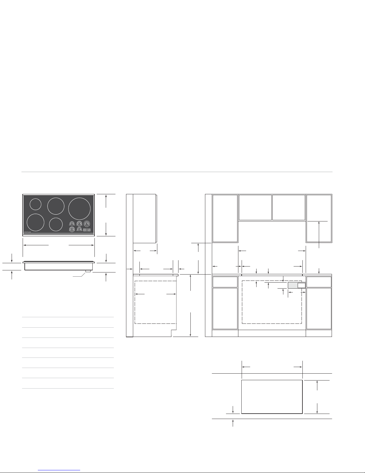
FRAMED MODEL ICBCT30I/S
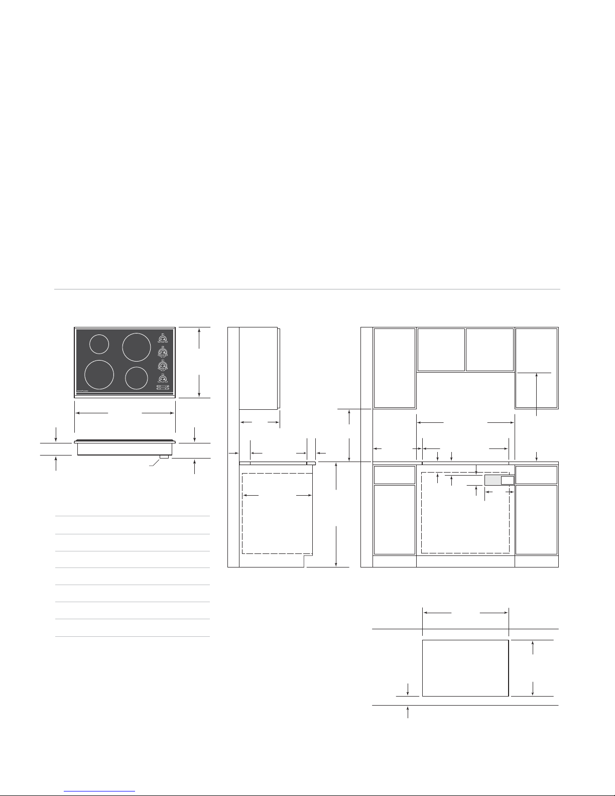
The illustrations below provide installation
specifications for Model ICBCT30I/S.
For ease of installation, 838 mm cabinets are
recommended for installation of Model
ICBCT30I/S.
A Wolf 762 mm or 914 mm built-in single oven
may be installed below Model ICBCT30I/S. For
Refer to installation instructions provided with
the built-in oven for additional specifications.
If Model ICBCT30I/S is installed above
cabinets, the electrical placement is not critical.
The appliance shall be installed in such a way
to allow disconnection of the appliance from
the supply mains after installation.
this installation, unless you are using cabinets
deeper than 610 mm, it is recommended that
the electrical supply be placed in the base
cabinet to the right of the oven.
INSTALLATION SPECIFICATIONS – MODEL ICBCT30I/S
533 mm
OVERALL
DEPTH
89 mm
762 mm
OVERALL WIDTH
TERMINAL BOX
114 mm
330 mm
max
51**
489 mm
mm
COOKTOP CUT-OUT
DEPTH
64 mm
Overall Dimensions
610 mm min
STANDARD
FLOOR TO
COUNTERTOP
MODEL ICBCT30I/S
min
914 mm
HEIGHT
457
mm
51 mm*min
CUT-OUT TO
COMBUSTIBLE
MATERIALS
(BOTH SIDES)
838 mm
RECOMMENDED
CABINET WIDTH
762 mm min
721 mm COOKTOP
CUT-OUT WIDTH
114 mm
95 mm
89 mm
min
762 mm OVEN OPENING
254
mm
E
762 mm
COUNTERTOP TO
COMBUSTIBLE
MATERIALS
ABOVE COOKTOP
Overall Width 762 mm
Overall Height 89 mm
Overall Depth 533 mm
Minimum Cabinet Depth 578 mm
Minimum Height Clearance* 114 mm
Cut-Out Width 721 mm
Cut-Out Depth 489 mm
*Minimum 152 mm clearance is required
between countertop and any combustible
surface directly below the cooktop.
For detailed terminal block dimensions,
refer to the illustration on page 7.
Dimensions may vary to±3mm.
*Minimum clearance from both side edges of cooktop cut-out to combustible materials up to 457 mm above countertop. **Minimum clearance
from rear edge of cooktop cut-out to combustible materials up to 457 mm above countertop.
721 mm
COOKTOP CUT-OUT WIDTH
Countertop Cut-Out
489 mm
64 mm
min
FRONT OF COUNTERTOP
COOKTOP
CUT-OUT DEPTH
9
WOLF INDUCTION COOKTOPS
FRAMED MODEL ICBCT36I/S
The illustrations below provide installation
specifications for Model ICBCT36I/S.
For ease of installation, 991 mm cabinets are
recommended for installation of Model
ICBCT36I/S.
A Wolf 762 mm or 914 mm built-in single oven
may be installed below Model ICBCT36I/S. For
this installation, unless you are using cabinets
deeper than 610 mm, it is recommended that
the electrical supply be placed in the base
cabinet to the right of the oven.
INSTALLATION SPECIFICATIONS – MODEL ICBCT36I/S
533 mm
OVERALL
DEPTH
89 mm
914 mm
OVERALL WIDTH
TERMINAL BOX
114 mm
330 mm
max
51**
489 mm
mm
COOKTOP CUT-OUT
DEPTH
Overall Dimensions
610 mm min
MODEL ICBCT36I/S
457
mm
64 mm
min
914 mm
STANDARD
FLOOR TO
COUNTERTOP
HEIGHT
Refer to installation instructions provided with
the built-in oven for additional specifications.
If Model ICBCT36I/S is installed above
cabinets, the electrical placement is not critical.
The appliance shall be installed in such a way
to allow disconnection of the appliance from
the supply mains after installation.
51 mm*min
CUT-OUT TO
COMBUSTIBLE
MATERIALS
(BOTH SIDES)
RECOMMENDED CABINET WIDTH
991 mm
914 mm min
873 mm
COOKTOP CUT-OUT WIDTH
114 mm
95 mm
min
914mmOVENOPENING
89 mm
254
mm
762 mm
COUNTERTOP TO
COMBUSTIBLE
MATERIALS
ABOVE COOKTOP
E
Overall Width 914 mm
Overall Height 89 mm
Overall Depth 533 mm
Minimum Cabinet Depth 578 mm
Minimum Height Clearance* 114 mm
Cut-Out Width 873 mm
Cut-Out Depth 489 mm
*Minimum 152 mm clearance is required
between countertop and any combustible
surface directly below the cooktop.
For detailed terminal block dimensions,
refer to the illustration on page 7.
Dimensions may vary to±3mm.
10
*Minimum clearance from both side edges of cooktop cut-out to combustible materials up to 457 mm above countertop. **Minimum clearance from
rear edge of cooktop cut-out to combustible materials up to 457 mm above countertop.
873 mm
COOKTOP CUT-OUT WIDTH
Countertop Cut-Out
489 mm
64 mm
min
FRONT OF COUNTERTOP
COOKTOP
CUT-OUT DEPTH
INSTALLATION INSTRUCTIONS
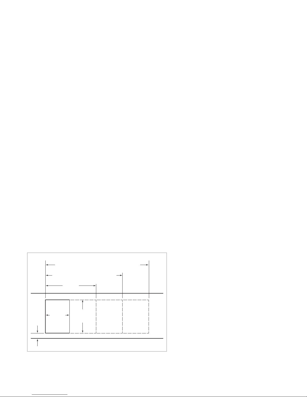
MULTIPLE COOKTOP INSTALLATION
If the framed induction cooktop is to be used
with any combination of additional cooktop
units or modules with a filler strip, the cut-out
width is calculated by adding the corresponding units’ cut-out dimensions plus 32 mm for
each additional unit. Refer to the illustration
below.
IMPORTANT NOTE:
For Model ICBCT15I/S,
the cut-out width should be increased from
340 mm to 356 mm when installed with
multiple units.
IMPORTANT NOTE:
Unframed induction
cooktops are not designed to be installed in
combination with other cooktops.
IMPORTANT NOTE:
When multiple units are
installed side by side, each unit must have its
own separate recommended electrical circuit.
When two or more modules are installed
together, an integrated module filler strip
(IFILLER/S) is recommended. If a 762 mm
downdraft ventilation system is also installed,
an integrated module support for downdraft
ventilation (ISUPPORT) is also required.
Contact your Wolf dealer for information on
these accessory components.
ACCESSORIES
Optional accessories are available
through your
Wolf dealer. To
obtain local dealer
information, visit
our website,
wolfappliance.com.
1518 mm – FOUR MODULES WIDTH OR
1511 mm – 762 mm COOKTOP AND TWO MODULES OR
1276 mm – 914 mm COOKTOP AND ONE MODULE
1130 mm – THREE MODULES WIDTH OR
1124 mm – 762 mm COOKTOP AND ONE MODULE
743 mm
TWO MODULES WIDTH
356 mm
64 mm
min
Countertop cut-out dimensions for installation of multiple cooktops
CUT-OUT
WIDTH
FRONT OF COUNTERTOP
489 mm
CUT-OUT
DEPTH
11

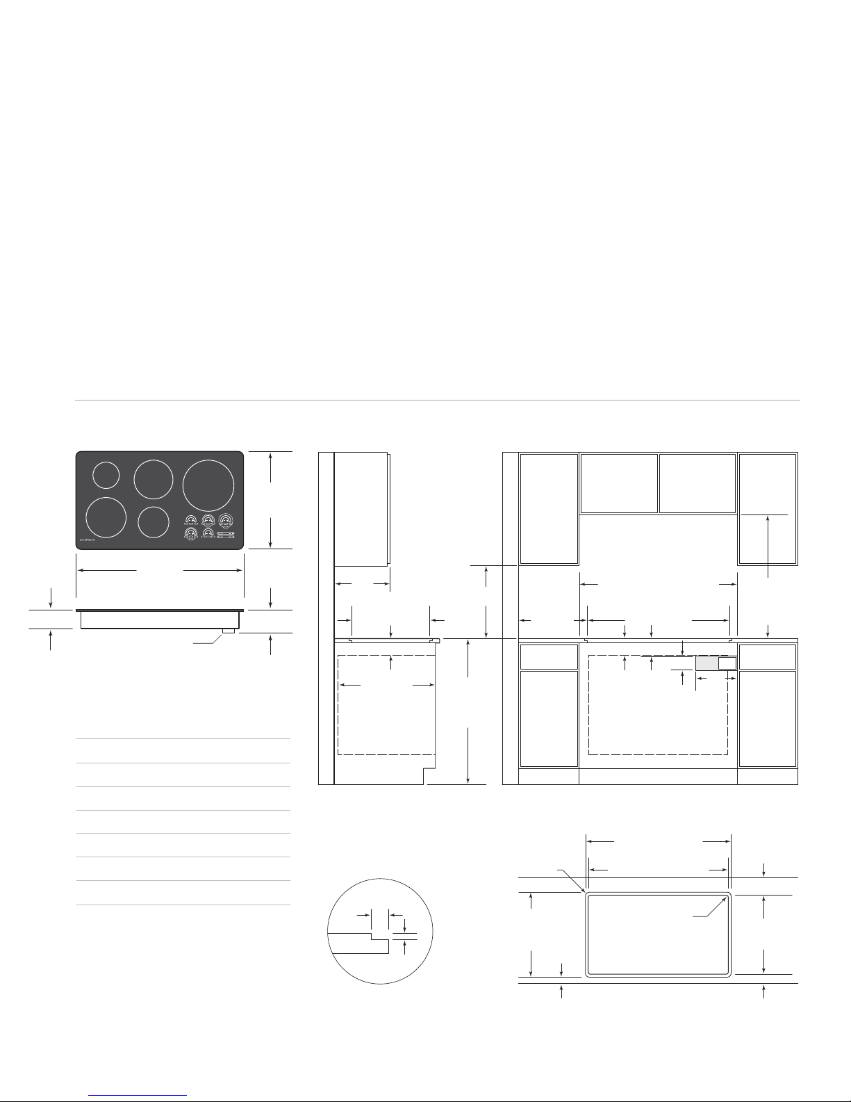
WOLF INDUCTION COOKTOPS
UNFRAMED MODEL ICBCT30IU
The illustrations below provide installation
specifications for Model ICBCT30IU.
For ease of installation, 838 mm cabinets are
recommended for installation of Model ICBCT30IU.
A Wolf 762 mm built-in single oven may be
installed below Model ICBCT30IU. For this
installation, unless you are using cabinets
deeper than 610 mm, it is recommended that
the electrical supply be placed in the base
cabinet to the right of the oven. Refer to installation instructions provided with the built-in
oven for additional specifications.
INSTALLATION SPECIFICATIONS – MODEL ICBCT30IU
533 mm
OVERALL
DEPTH
104 mm
762 mm
OVERALL WIDTH
TERMINAL BOX
127 mm
330 mm
max
SEE COUNTERTOP
CUT-OUT BELOW
102 mm min
Overall Dimensions
610 mm min
MODEL ICBCT30IU
457
mm
914 mm
STANDARD
FLOOR TO
COUNTERTOP
HEIGHT
If Model ICBCT30IU is installed above cabinets,
electrical placement is not critical. The appliance shall be installed in such a way to allow
disconnection of the appliance from the supply
mains after installation.
For Model ICBCT30IU installation options, refer
to Unframed Installations on pages 14–15.
IMPORTANT NOTE:
For flush mount applications, it is recommended to measure the
cooktop glass before cutting the countertop to
ensure a proper fit. Small variances may exist
between the template and the cooktop.
838 mm
51 mm*min
CUT-OUT TO
COMBUSTIBLE
MATERIALS
(BOTH SIDES)
RECOMMENDED
CABINET WIDTH
762 mm min
SEE COUNTERTOP
CUT-OUT BELOW
114 mm
102 mm
TO OVEN
OPENING
89 mm
min
762mmOVENOPENING
254
mm
762 mm
COUNTERTOP TO
COMBUSTIBLE
MATERIALS
ABOVE COOKTOP
E
Overall Width 762 mm
Overall Height 102 mm
Overall Depth 533 mm
Minimum Cabinet Depth 578 mm
Minimum Height Clearance*
127 mm
Cut-Out Width 721 mm
Cut-Out Depth 492 mm
*Minimum 165 mm clearance is required
between countertop and any combustible
surface directly below the cooktop.
For detailed terminal block dimensions,
refer to the illustration on page 7.
Dimensions may vary to±3mm.
12
*Minimum clearance from both side edges and back edge of cooktop cut-out to combustible materials up to 457 mm above countertop.
Countertop Cut-Out
RECESSED AREA FOR
FLUSH MOUNT INSTALLATION ONLY
COUNTERTOP
PROFILE
22
max
mm
8mm
**Minimum dimension, but may be exceeded by up to 3 mm.
FOR FLUSH MOUNT
INSTALLATION ONLY
33 mm
RADIUS
537 mm**
RECESSED AREA
40 mm
765 mm**
RECESSED AREA FOR
FLUSH MOUNT INSTALLATION ONLY
721 mm COOKTOP
CUT-OUT WIDTH
11 mm RADIUS
FRONT OF COUNTERTOP
51 mm*
492 mm
COOKTOP
CUT-OUT DEPTH
62 mm
INSTALLATION INSTRUCTIONS
UNFRAMED
The illustrations below provide installation
specifications for Model ICBCT36IU.
For ease of installation, 991 mm cabinets are
recommended for installation of Model ICBCT36IU.
A Wolf 914 mm built-in single oven may be
installed below Model ICBCT36IU. For this
installation, unless you are using cabinets
deeper than 610 mm, it is recommended that
the electrical supply be placed in the base
cabinet to the right of the oven. Refer to installation instructions provided with the built-in
oven for additional specifications.
MODEL ICBCT36IU
If Model ICBCT36IU is installed above cabinets,
electrical placement is not critical. The appliance shall be installed in such a way to allow
disconnection of the appliance from the supply
mains after installation.
For Model ICBCT36IU installation options, refer
to Unframed Installations on pages 14–15.
IMPORTANT NOTE:
tions, it is recommended to measure the
cooktop glass before cutting the countertop to
ensure a proper fit. Small variances may exist
between the template and the cooktop.
INSTALLATION SPECIFICATIONS – MODEL ICBCT36IU
533 mm
OVERALL
DEPTH
For flush mount applica-
914 mm
OVERALL WIDTH
104 mm
TERMINAL BOX
Overall Dimensions
MODEL ICBCT36IU
Overall Width 914 mm
Overall Height 102 mm
Overall Depth 533 mm
Minimum Cabinet Depth 578 mm
Minimum Height Clearance*
Cut-Out Width 873 mm
Cut-Out Depth 492 mm
*Minimum 165 mm clearance is required
between countertop and any combustible
surface directly below the cooktop.
For detailed terminal block dimensions,
refer to the illustration on page 7.
Dimensions may vary to±3mm.
127 mm
127 mm
330 mm
max
SEE COUNTERTOP
CUT-OUT BELOW
min
102 mm
610 mm min
*Minimum clearance from both side edges and back edge of cooktop cut-out to combustible materials up to 457 mm above countertop.
457
mm
914 mm
STANDARD
FLOOR TO
COUNTERTOP
HEIGHT
51 mm*min
CUT-OUT TO
COMBUSTIBLE
MATERIALS
(BOTH SIDES)
Countertop Cut-Out
RECESSED AREA FOR
FLUSH MOUNT INSTALLATION ONLY
COUNTERTOP
PROFILE
22
mm max
8mm
**Minimum dimension, but may be exceeded by up to 3 mm.
RECESSED AREA
FOR FLUSH MOUNT
INSTALLATION ONLY
33 mm
RADIUS
537 mm**
40 mm
FLUSH MOUNT INSTALLATION ONLY
991 mm
RECOMMENDED CABINET WIDTH
914 mm min
SEE COUNTERTOP
CUT-OUT BELOW
114 mm
102 mm min
TO OVEN
OPENING
914 mm OVEN OPENING
RECESSED AREA FOR
COOKTOP CUT-OUT WIDTH
FRONT OF COUNTERTOP
89 mm
918 mm**
873 mm
11 mm RADIUS
254
mm
E
COUNTERTOP TO
ABOVE COOKTOP
CUT-OUT DEPTH
762 mm
COMBUSTIBLE
MATERIALS
51 mm*
492 mm
COOKTOP
62 mm
13

WOLF INDUCTION COOKTOPS
UNFRAMED
Flush mount installations are intended
for granite, solid surface or stone countertop surfaces only. Failure to use high
heat resistant surface will result in countertop damage if hot cooking utensils are
accidentally moved off the cooking
surface.
INSTALLATIONS
MODELS ICBCT30IU AND ICBCT36IU
Unframed induction cooktop Models
ICBCT30IU and ICBCT36IU can be mounted
flush with the top of the countertop or as a
frameless installation with the glass mounted
on top of the countertop surface.
IMPORTANT NOTE:
The materials required
for a flush mount installation are provided with
the unframed Models ICBCT30IU and
ICBCT36IU. Refer to the instructions provided
with the unframed cooktop installation kit
(#811358) for additional specifications.
FLUSH MOUNT INSTALLATION
There are two options for a flush mount
installation of the unframed induction cooktop;
Option 1 and Option 2.
OPTION 1:
For this flush mount installation, a
recessed area surrounding the standard countertop cut-out is required. Fabrication of the
recessed area must take place before the final
countertop installation. A template of the countertop cut-out is provided with the unframed
cooktop for fabrication purposes.
IMPORTANT NOTE:
This fabrication method is
not recommended for molded backsplash style
countertops (triple cove).
For countertop cut-out dimensions, refer to
the Installation Specifications illustration on
page 12 for Model ICBCT30IU and page 13 for
Model ICBCT36IU.
In order to rout the required recessed area for
this flush mount installation, a second
template must be made from 13 mm plywood.
The template will be used as a guide for a top
bearing router bit.
Make the wood template wide enough so that
clamps used to hold this template to the countertop do not interfere with the router base.
The cut-out dimension of the wood template
should match the outer perimeter of the
template supplied with the cooktop.
Center the wood template over the existing
cut-out in the countertop and clamp. It may be
helpful to use medium-strength double-sided
tape to adhere the template to the countertop;
this will keep the template from shifting during
the routing operation. Make sure that the
adhesive can be easily removed by testing it
on a scrap piece of the countertop. Using a top
bearing router bit with the wood template as a
guide, rout out a 8 mm deep recessed area in
the countertop cut-out.
14
INSTALLATION INSTRUCTIONS
UNFRAMED INSTALLATIONS
FLUSH MOUNT INSTALLATION
OPTION 2:
For this flush mount installation,
the countertop cut-out will be the same size as
the outer edge of the glass top. It is recommended that cooktop itself be used as the
template for the cut-out. Turn the cooktop over
and mark the opening using the glass top as a
template.
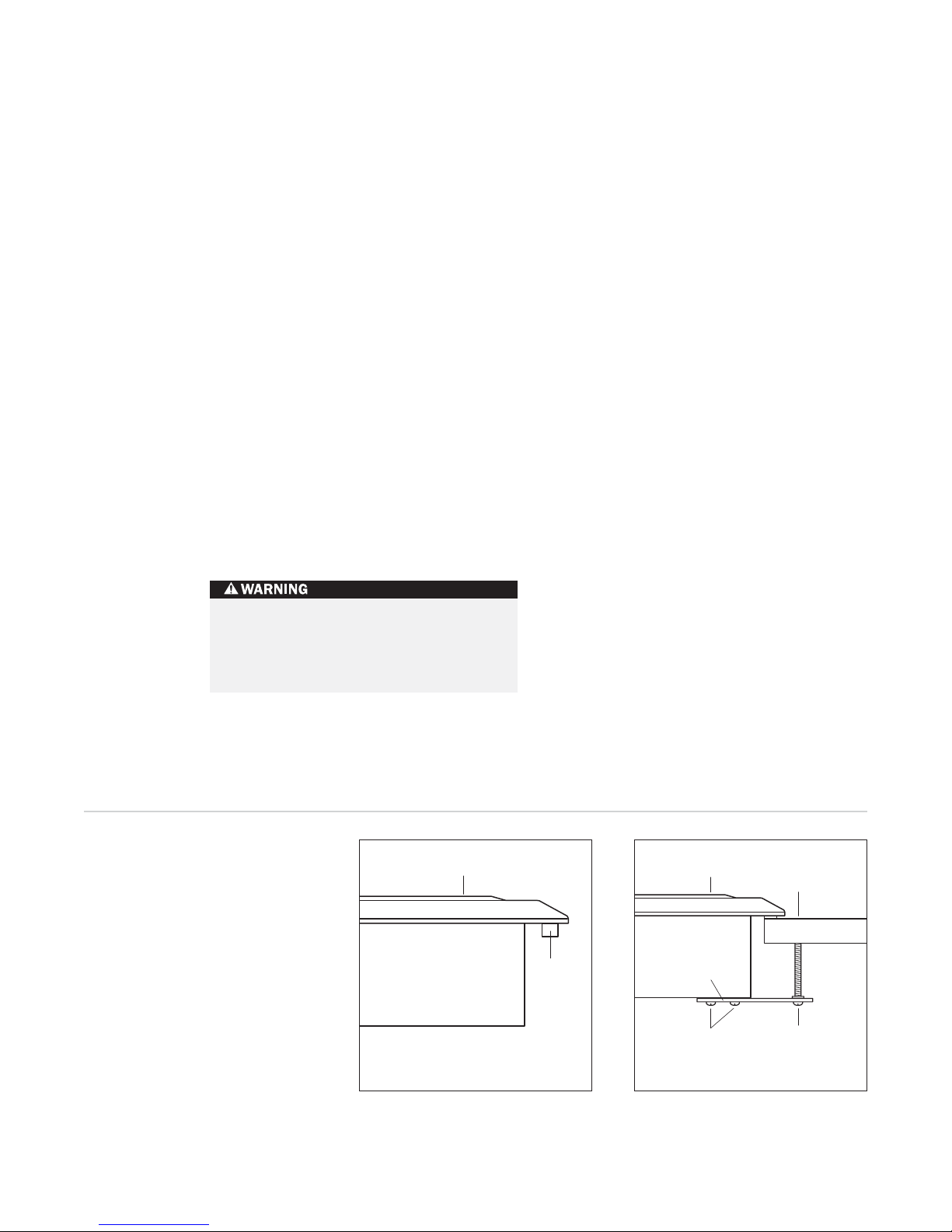
It will be necessary to attach L-shaped brackets
or cleats to the inner perimeter of the cut-out
to support the cooktop. The top edge of the
bracket can be no wider than 22 mm and will
be attached 8 mm below the surface of the
countertop. Refer to the illustration below.
Attachment of the brackets is up to the
installer's discretion, wherever enough countertop material is present.
For additional support in the cut-out area,
adhere scrap countertop material to the
bottom side of the countertop. Consult your
countertop supplier for the proper methods of
attachment.
FRAMELESS INSTALLATION
Unframed induction cooktop Models
ICBCT30IU and ICBCT36IU can be installed as a
frameless application, with the glass mounted
on top of the countertop surface. For countertop cut-out dimensions, refer to the Installation
Specifications illustration on page 12 for Model
ICBCT30IU and page 13 for Model ICBCT36IU.
8mm
22 mm
Flush mount installation brackets
L-Shaped
Brackets
15

IMPORTANT
NOTE
WOLF INDUCTION COOKTOPS
ELECTRICAL REQUIREMENTS
Verify that power is disconnected from
the electrical box before proceeding.
REQUIRED POWER SUPPLY
FOR SINGLE PHASE CIRCUITS
Wolf induction cooktops require a separate,
grounded 3-wire service for single phase
circuits or 5-wire service for three phase
circuits with its own circuit breaker. Locate the
electrical supply within the shaded area shown
in the Installation Specifications illustration for
your specific model on pages 8–13.
This appliance
must be installed
in accordance
with local codes.
Model ICBCT15I/S
220-240 V AC, 50/60 Hz, 3.6 kW,
20 amp service
Model ICBCT30I/S and ICBCT30IU
220-240 V AC, 50/60 Hz, 7.2 kW,
40 amp service
Model ICBCT36I/S and ICBCT36IU
220-240 V AC, 50/60 Hz, 10.2 kW,
50 amp service
REQUIRED POWER SUPPLY
FOR THREE PHASE CIRCUITS
Model ICBCT15I/S
220-240 V AC, 50/60 Hz, 3.6 kW,
25 amp service per line
Model ICBCT30I/S and ICBCT30IU
220-240 V AC, 50/60 Hz, 7.2 kW,
25 amp service per line
Model ICBCT36I/S and ICBCT36IU
220-240 V AC, 50/60 Hz, 10.2 kW,
25 amp service per line
16
INSTALLATION INSTRUCTIONS
ELECTRICAL REQUIREMENTS
This appliance must be installed in accordance
with local codes. The correct voltage,
frequency and amperage must be supplied to
the appliance from a dedicated, grounded
circuit which is protected by a properly sized
circuit breaker or time delay fuse. The proper
voltage, frequency and amperage ratings are
listed on the product rating plate, located on
the underside of the cooktop.
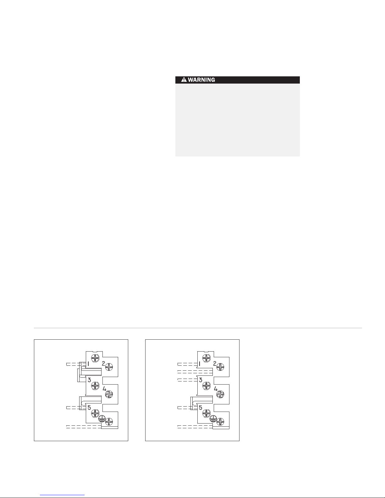
The cooktop is provided with a terminal box.
Refer to the wiring diagram below.
The complete appliance must be properly
grounded at all times when electrical
power is applied.
Do not ground the appliance with the
neutral (white) house supply wire. A
separate ground wire must be utilized.
Improper connection can result in a fire
hazard!
N
L1
GROUND
Single phase wiring diagram
L1
L2
L3
N
GROUND
Three phase wiring diagram
17
WOLF INDUCTION COOKTOPS
ACCESSORIES
Optional accessories are available
through your
Wolf dealer. To
obtain local dealer
information, visit
our website,
wolfappliance.com.
COOKTOP
INSTALLATION
Attach the foam strip to the underside of the
cooktop frame. Refer to the illustration below.
IMPORTANT NOTE:
For unframed installation,
adhere foam strip to the outer edge of the
glass, not the support frame.
Gently lower the cooktop into the cut-out area
in the countertop and center. Check that the
front edge of the cooktop is parallel to the
front edge of the countertop. Check that all
required clearances are met.
Attach the brackets to the bottom of the unit,
as shown in the illustration below. Install the
clamping screws into the bracket and tighten
until the screws contact the underside of the
countertop.
IMPORTANT NOTE:
Do not over tighten the screws.
Do not seal the cooktop
to the countertop. It must be removed if
service is necessary.
If the ceramic glass top of the cooktop is
broken, turn off power to the unit. Do
not operate until glass has been replaced
by a Wolf authorized service center.
BEFORE OPERATING
Clean the ceramic glass surface carefully using
the Cooktop Cleaning Crème provided with the
cooktop. Remove all cleaning residue.
Read the entire Wolf Induction Cooktops
Use & Care Information included with the
cooktop. Important safety and service information is contained within the book.
COOKTOP
IMPORTANT NOTE:
REMOVAL
This procedure should
only be performed by a Wolf authorized
service center.
If it is necessary to remove the cooktop for
cleaning or service, disconnect the electrical
supply. Remove the mounting brackets on the
right and left side of the unit and remove the
cooktop. Reinstall in the reverse order.
IMPORTANT NOTE:
For flush mount installations, use a razor blade to cut around the RTV
seal. A new RTV installation kit (811358) will be
required to reinstall the cooktop. This kit is
available through your Wolf dealer. To obtain
local dealer information, visit our website,
wolfappliance.com.
18
COOKTOP
FOAM
STRIP
Foam strip Installation brackets
COOKTOP
BRACKET
BRACKET
SCREWS
COUNTERTOP
89 mm
CLAMPING
SCREW

INSTALLATION INSTRUCTIONS
TROUBLESHOOTING
IF COOKTOP DOES NOT OPERATE
IMPORTANT NOTE:
If the induction cooktop
does not operate properly, follow these
troubleshooting steps:
Verify that power is being supplied to the
cooktop.
Check electrical connections to ensure that
the installation has been completed
correctly.
Follow troubleshooting procedures as
described in the Wolf Induction Cooktops
Use & Care Information.
If the power bar indicator lights operate but
the unit shows that it is in Lock mode, the
unit is in Showroom mode. Contact your
localWolfdealer.
If the cooktop still does not work, contact
a Wolf authorized service center. Do not
attempt to repair the cooktop yourself.
Wolf is not responsible for service required
to correct a faulty installation.
The unit must be disconnected from
power prior to service.
19

CONTACT
INFORMATION
Website:
wolfappliance.com
WOLF INDUCTION COOKTOPS
IF YOU NEED SERVICE
If service is necessary, maintain the quality
built into your induction cooktop by calling
a Wolf authorized service center.
To obtain the name and number of a
Wolf authorized service center, visit our
website,
wolfappliance.com
.
When calling for service, you will need the
cooktop model and serial numbers. Both
numbers are listed on the rating plate,
located on the underside of the cooktop.
Refer to the illustration on page 5 for
location of the rating plate.
20
The information and images in this book are the
copyright property of Wolf Appliance, Inc., an
affiliate of Sub-Zero, Inc. Neither this book nor any
information or images contained herein may be
copied or used in whole or in part without the
express written permission of Wolf Appliance, Inc.,
an affiliate of Sub-Zero, Inc.
©Wolf Appliance, Inc. all rights reserved.

INFORMACIÓN
DE CONTACTO
Página web:
wolfappliances.com
Cuando consulte las instrucciones que aparecen
en esta guía, encontrará símbolos de ADVERTENCIA y PRECAUCIÓN. Esta información en
recuadros es importante para instalar el equipo
de Wolf de forma segura y eficaz. Existen dos
tipos de posibles riesgos que pueden producirse
durante una instalación.
WOLF®es una marca comercial registrada de Wolf Appliance, Inc.
indica una situación en la que se pueden
sufrir heridas leves o provocar daños
secundarios al producto si no se siguen
las instrucciones.
indica peligro de que se produzcan heridas
personales graves o incluso puede provocar
la muerte si no se siguen las precauciones
especificadas.
Otro tipo de anotación que es importante
resaltar es la que se incluye en NOTA
IMPORTANTE: En esta nota se resalta la
información que resulta especialmente
importante para que la instalación se
realice sin problemas.
PLACAS DE INDUCCIÓN DE WOLF
INFORMACIÓN
DE LA PLACA
DE DATOS
Referencia del
modelo
Número de serie
REQUISITOS DE INSTALACIÓN
NOTA IMPORTANTE:
Guarde estas instrucciones
de instalación para que el inspector local pueda
utilizarlas.
Lea las instrucciones de instalación antes de
llevar a cabo la instalación.
Esta instalación debe ser realizada por un
técnico cualificado.
Instalador:
guarde estas instrucciones para
que el inspector local pueda utilizarlas como
referencia y, a continuación, entréguelas al
propietario del aparato.
Propietario:
lea y guarde estas instrucciones
para que pueda utilizarlas como referencia en
el futuro y asegúrese de leer la guía de uso y
mantenimiento antes de utilizar el aparato.
NOTA IMPORTANTE:
Este aparato debe instalarse siguiendo las normativas nacionales correspondientes. Se debe aplicar al aparato el voltaje,
la frecuencia y el amperaje adecuados desde una
instalación eléctrica resistente con toma de tierra
protegida por un fusible de retardo. El voltaje, la
frecuencia y el amperaje se muestran en la placa
de datos del producto.
Apunte la referencia del modelo y el número
de serie antes de instalar el aparato. Esta información se muestra en la placa de datos del
producto situada en la parte inferior de la
placa. Observe la siguiente ilustración.
ANTES DE COMENZAR
Es responsabilidad del propietario asegurarse
de que la instalación se realiza de manera
correcta. Esta placa debe ser instalada por un
técnico cualificado. Debe asegurarse de que la
instalación eléctrica es la correcta y que
cumple todos los códigos y normativas
nacionales.
Las instalaciones y reparaciones deben ser
realizadas por un contratista cualificado o
autorizado o por un electricista cualificado o
autorizado por el estado, provincia o región
en la que se va a instalar este aparato.
Compruebe que tiene todo lo necesario para
que la instalación se lleve a cabo de la manera
correcta. Es responsabilidad del instalador
dejar los espacios necesarios para la instalación que se especifican en la placa de datos
del producto. La placa de datos está ubicada
en la parte inferior del aparato.
Este aparato necesita una conexión a tierra;
consulte la sección Requisitos eléctricos en las
páginas 33 y 34.
Esta placa está diseñada para que se utilice
en espacios interiores.
placa de datos debajo
Ubicación de la placa de datos
22
Ubicación de la
de la placa
PLACAS DE INDUCCIÓN DE WOLF
PREPARACIÓN DEL
NOTA IMPORTANTE:
SITIO
La instalación de la placa
de inducción de Wolf debe cumplir los siguientes
requisitos de colocación. Las medidas que se
especifican son las mínimas para que el funcionamiento de la placa sea seguro. Observe la siguiente ilustración.
Para eliminar el riesgo de sufrir quemaduras
o de que se produzca un incendio al
alcanzar las superficies calientes, debe
evitar colocar armarios por encima de los
módulos de superficie. Si va a colocar
armarios, el riesgo se puede reducir al
instalar una campana de extracción que
sobresalga horizontalmente un mínimo de
127 mm de la parte inferior de los armarios.
COLOCACIÓN EN LA ENCIMERA
A)
Superficie mínima de encimera plana. Debe
ser igual o superior al ancho de la placa.
B)
Espacio mínimo de 25 mm desde el borde
lateral de la placa a cualquier superficie
combustible situada a 457 mm por encima de
la placa (área sombreada de la ilustración).
MEDIDAS DE LOS ARMARIOS
SUPERIORES
C)
El espacio mínimo entre los armarios laterales
superiores debe ser igual o superior al ancho
nominal de la placa o placas.
D)
Debe existir una distancia vertical mínima de
457 mm desde la encimera hasta la parte
inferior de los armarios laterales con una
distancia lateral mínima.
E)
La distancia vertical mínima entre la encimera
y los materiales combustibles situados por
encima de la placa debe ser de 762 mm.
F)
Distancia mínima de 25 mm a la pared trasera.
G)
El fondo máximo de los armarios superiores
laterales situados por encima de la placa
debe ser de 330 mm con una distancia
lateral mínima.
E
F
B
Distancias mínimas de instalación
Si no coloca la placa siguiendo las
distancias de separación correctas, es
posible que se produzca un incendio.
C
G
D
B
A
23
INSTRUCCIONES DE INSTALACIÓN
ESPECIFICACIONES DE
LA
INSTALACIÓN
Las ilustraciones de las páginas 25–30 proporcionan las medidas totales, las especificaciones de la
instalación y las medidas del corte de la encimera
para cada uno de los modelos de placas de
inducción de Wolf.
Esta placa está diseñada para que se adapte a un
armario de base estándar de 610 mm de fondo
con una encimera de 635 mm de fondo. Antes de
cortar la encimera, compruebe que la placa va a
quedar separada de las paredes laterales del
armario inferior.
Se necesita dejar un espacio para el bloque de
terminales en la parte trasera derecha de la placa.
Observe la siguiente ilustración para ver las
medidas.
PLACAS DE INDUCCIÓN CON MARCO
NOTA IMPORTANTE:
Es necesario dejar un
espacio mínimo de altura de 152 mm entre la
placa y cualquier superficie combustible que se
encuentre justo debajo de la placa. Esto incluye
los bordes superiores de los cajones situados
directamente debajo de la unidad. Si instala un
estante debajo del aparato, debe dejar un espacio
de 25 mm en la parte trasera del armario para
que la ventilación sea correcta. Si no deja este
espacio, es posible que se reduzca el rendimiento
del aparato o que se produzcan daños en el
mismo.
Las placas de inducción de Wolf están diseñadas
para que se puedan instalar junto con otras
placas.
NOTA IMPORTANTE:
Cuando instale varias
placas juntas y /o módulos, consulte las dimensiones de corte de la encimera en la página 28.
Las placas de inducción de Wolf pueden
instalarse con un sistema de ventilación de tiro
ascendente de Wolf. Consulte las instrucciones de
instalación que se proporcionan con el sistema
de ventilación de tiro ascendente para obtener
más información.
PLACAS DE INDUCCIÓN SIN MARCO
NOTA IMPORTANTE:
Es necesario dejar un
espacio mínimo de altura de 165 mm entre la
placa y cualquier superficie combustible que se
encuentre justo debajo de la placa. Esto incluye
los bordes superiores de los cajones situados
directamente debajo de la unidad. Si instala un
estante debajo del aparato, debe dejar un espacio
de 25 mm en la parte trasera del armario para
que la ventilación sea correcta. Si no deja este
espacio, es posible que se reduzca el rendimiento
del aparato o que se produzcan daños en el
mismo.
NOTA IMPORTANTE:
Las placas de inducción
sin marco de Wolf están diseñadas para que se
puedan instalar junto con otras placas.
NOTA IMPORTANTE:
Las placas de inducción
sin marco no se pueden instalar con un sistema
de ventilación de tiro ascendente.
Si desea consultar las opciones de instalación
de las placas de inducción sin marco, consulte
la sección Instalación sin marco en las
páginas 31–32.
32 mm
56
mm
84
24
mm
Medidas del bloque de terminales
24
mm
22 mm
PLACAS DE INDUCCIÓN DE WOLF
MODELO ICBCT15I/S CON MARCO
Las siguientes ilustraciones proporcionan las
especificaciones de instalación del modelo
ICBCT15I/S.
Si instala el modelo ICBCT15I/S encima de los
armarios, la colocación de la toma eléctrica no es
importante. El aparato se instalará de tal forma
que se pueda desconectar de la red después de
su instalación.
ESPECIFICACIONES DE LA INSTALACIÓN – MODELO ICBCT15I/S
533 mm
PROFUNDIDAD
TOTAL
89 mm
381 mm
ANCHURA TOTAL
114 mm
mm
51**
330 mm
máx
489 mm
PROFUNDIDAD
DE CORTE DE LA
SUPERFICIE
DE
COCCIÓN
64 mm
mín
457
mm
CAJA PARA TERMINAL
Medidas totales
914 mm
ALTURA
MODELO ICBCT15I/S
Anchura total 381 mm
ESTÁNDAR DEL
SUELO
ALA
ENCIMERA
Altura total 89 mm
Profundidad total 533 mm
Fondo mínimo del armario 578 mm
Espacio de altura mínimo* 114 mm
NOTA: La aplicación que se muestra permite la instalación de dos módulos contiguos de 381 mm con un armario con una anchura recomendada
de 838 mm. 457 mm de anchura de armario recomendada para la instalación de un solo módulo o superficie de cocción de 381 mm. *Espacio mínimo
desde ambos bordes laterales del corte de la superficie de cocción hasta la superficie inflamable situada a 457 mm por encima de la encimera. **Espacio
mínimo desde el borde trasero del corte de la superficie de cocción a la superficie inflamable situada a 457 mm sobre la encimera.
Ancho del corte 340 mm
Profundidad del corte 489 mm
*Es necesario dejar un espacio mínimo de
altura de 152 mm entre la encimera y
cualquier superficie combustible que se
encuentre justo encima de la placa.
Si desea obtener las medidas detalladas
del bloque de terminales, consulte la
ilustración en la página 24.
Las medidas pueden variar±3mm.
Corte de la encimera
51 mm* mín
DESDE CORTE A
LOS MATERIALES
INFLAMABLES
(AMBOS
LADOS)
64 mm
mín
838 mm ANCHURA RECOMENDADA
DEL ARMARIO
340 mm ANCHURA
DE CORTE DE
LA SUPERFICIE
DE
COCCIÓN
114 mm
E
381
mm
381 mm
340 mm ANCHURA DE CORTE
DE LA SUPERFICIE
DE
COCCIÓN
PROFUNDIDAD
DE CORTE
DE LA SUPERFICIE
DE COCCIÓN
PARTE DELANTERA DE LA ENCIMERA
489 mm
762 mm
ENCIMERA
A MATERIALES
COMBUSTIBLES
SOBRE
LA SUPERFICIE
DE COCCIÓN
25
INSTRUCCIONES DE INSTALACIÓN
MODELO ICBCT30I/S CON MARCO
Las siguientes ilustraciones proporcionan las
especificaciones de instalación del modelo
ICBCT30I/S.
Para que la instalación le resulte más sencilla,
cuando instale el modelo ICBCT30I/S le
recomendamos que utilice armarios de 838 mm.
Debajo del modelo ICBCT30I/S se puede instalar
un horno sencillo de Wolf integrado de 762 mm
o 914 mm. Para realizar esta instalación, a menos
que utilice armarios con una profundidad mayor
a 610 mm, se recomienda colocar la alimentación
eléctrica en el armario de la base a la derecha
del horno.
ESPECIFICACIONES DE LA INSTALACIÓN – MODELO ICBCT30I/S
533 mm
PROFUNDIDAD
TOTAL
89 mm
762 mm
ANCHURA TOTAL
CAJA PARA TERMINAL
114 mm
330 mm
máx
PROFUNDIDAD
51**
mm
DE LA SUPERFICIE
489 mm
DE CORTE
DE COCCIÓN
64 mm
mín
457
mm
Medidas totales
610 mm mín
MODELO ICBCT30I/S
Anchura total 762 mm
914 mm
ALTURA
ESTÁNDAR
DEL
SUELO A LA
ENCIMERA
Altura total 89 mm
Profundidad total 533 mm
Fondo mínimo del armario 578 mm
*Espacio mínimo desde ambos bordes laterales del corte de la superficie de cocción hasta la superficie inflamable situada a 457 mm por encima de
la encimera. **Espacio mínimo desde el borde trasero del corte de la superficie de cocción a la superficie inflamable situada a 457 mm sobre la encimera.
Espacio de altura mínimo* 114 mm
Ancho del corte 721 mm
Profundidad del corte 489 mm
Cortedelaencimera
Consulte las instrucciones de instalación que
se proporcionan con el horno integrable para
obtener más información.
Si instala el modelo ICBCT30I/S encima de los
armarios, la colocación de la toma eléctrica no
es importante. El aparato se instalará de tal
forma que se pueda desconectar de la red
después de su instalación.
51 mm* mín
DESDE CORTE A
LOS MATERIALES
INFLAMABLES
(AMBOS
LADOS)
838 mm ANCHURA RECOMENDADA
DEL ARMARIO
762 mm mín
721 mm ANCHURA
DE CORTE
DE LA SUPERFICIE
DE
COCCIÓN
114 mm
95 mm
mín
762 mm APERTURA DEL HORNO
DE LA SUPERFICIE DE COCCIÓN
89 mm
721 mm
ANCHURA DE CORTE
254
mm
A MATERIALES
COMBUSTIBLES
SUPERFICIE
DE COCCIÓN
E
762 mm
ENCIMERA
SOBRE LA
*Es necesario dejar un espacio mínimo de
altura de 152 mm entre la encimera y
cualquier superficie combustible que se
encuentre justo encima de la placa.
Si desea obtener las medidas detalladas
del bloque de terminales, consulte la
ilustración en la página 24.
Las medidas pueden variar±3 mm.
26
64 mm
mín
PARTE DELANTERA DE LA ENCIMERA
489 mm
PROFUNDIDAD
DE CORTE
DE LA SUPERFICIE
DE COCCIÓN
PLACAS DE INDUCCIÓN DE WOLF
MODELO ICBCT36I/S CON MARCO
Las siguientes ilustraciones proporcionan las
especificaciones de instalación del modelo
ICBCT36I/S.
Para que la instalación le resulte más sencilla,
cuando instale el modelo ICBCT36I/S le
recomendamos que utilice armarios de 991 mm.
Debajo del modelo ICBCT36I/S se puede instalar
un horno sencillo de Wolf integrado de 762 mm
o 914 mm. Para realizar esta instalación, a menos
que utilice armarios con una profundidad mayor
a 610 mm, se recomienda colocar la alimentación
eléctrica en el armario de la base a la derecha
del horno.
ESPECIFICACIONES DE LA INSTALACIÓN – MODELO ICBCT36I/S
914 mm
ANCHURA TOTAL
89 mm
CAJA PARA TERMINAL
Medidas totales
MODELO ICBCT36I/S
533 mm
PROFUNDIDAD
TOTAL
114 mm
330 mm
máx
PROFUNDIDAD
51**
mm
DE LA SUPERFICIE
Consulte las instrucciones de instalación que
se proporcionan con el horno integrable para
obtener más información.
Si instala el modelo ICBCT36I/S encima de los
armarios, la colocación de la toma eléctrica no
es importante. El aparato se instalará de tal
forma que se pueda desconectar de la red
después de su instalación.
489 mm
DE CORTE
DE COCCIÓN
610 mm mín
64 mm
mín
914 mm
ALTURA
ESTÁNDAR
DEL SUELO
ALA
ENCIMERA
457
mm
51 mm* mín
DESDE CORTE A
LOS MATERIALES
INFLAMABLES
(AMBOS
LADOS)
991 mm
ANCHURA RECOMENDADA
DEL ARMARIO
ANCHURA DE CORTE DE
LA SUPERFICIE DE COCCIÓN
95 mm
mín
762 mm APERTURA DEL HORNO
914 mm mín
873 mm
114 mm
89 mm
254
mm
ENCIMERA A
MATERIALES
COMBUSTIBLES
SUPERFICIE
DE COCCIÓN
E
762 mm
SOBRE LA
Anchura total 914 mm
Altura total 89 mm
Profundidad total 533 mm
Fondo mínimo del armario 578 mm
Espacio de altura mínimo* 114 mm
Ancho del corte 873 mm
Profundidad del corte 489 mm
*Es necesario dejar un espacio mínimo de
altura de 152 mm entre la encimera y
cualquier superficie combustible que se
encuentre justo encima de la placa.
Si desea obtener las medidas detalladas
del bloque de terminales, c onsulte la
ilustración en la página 24.
Las medidas pueden variar±3mm.
*Espacio mínimo desde ambos bordes laterales del corte de la superficie de cocción hasta la superficie inflamable situada a 457 mm por encima de la encimera.
**Espacio mínimo desde el borde trasero del corte de la superficie de cocción a la superficie inflamable situada a 457 mm sobre la encimera.
873 mm
ANCHURA DE CORTE
DE LA SUPERFICIE DE COCCIÓN
Corte de la encimera
489 mm
PROFUNDIDAD
64 mm
mín
PARTE DELANTERA DE LA ENCIMERA
DE CORTE
DE LA SUPERFICIE
DE COCCIÓN
27
 Loading...