

Wolf ICBCG304P/S/LP, ICBCG304T/S/LP, ICBCG304P/S, ICBCG365T/S, ICBCG365T/S/LP Installation Manual
...
GAS COOKTOPS
INSTALLATION GUIDE
GUÍA DE INSTALACIÓN
GUIDE D’INSTALLATION
GUIDA ALL’INSTALLAZIONE
INSTALLATIONSANLEITUNG
WF Intl GCooktops IG MultiLang 824551A 10-13.indd 1 2/19/14 12:08 PM
2 | English
GAS COOKTOPS
Contents
2 Gas Cooktops
3 Specications
5 Installation
5 Troubleshooting
Features and specications are subject to change at any
time without notice. Visit wolfappliance.com/specs for the
most up-to-date information.
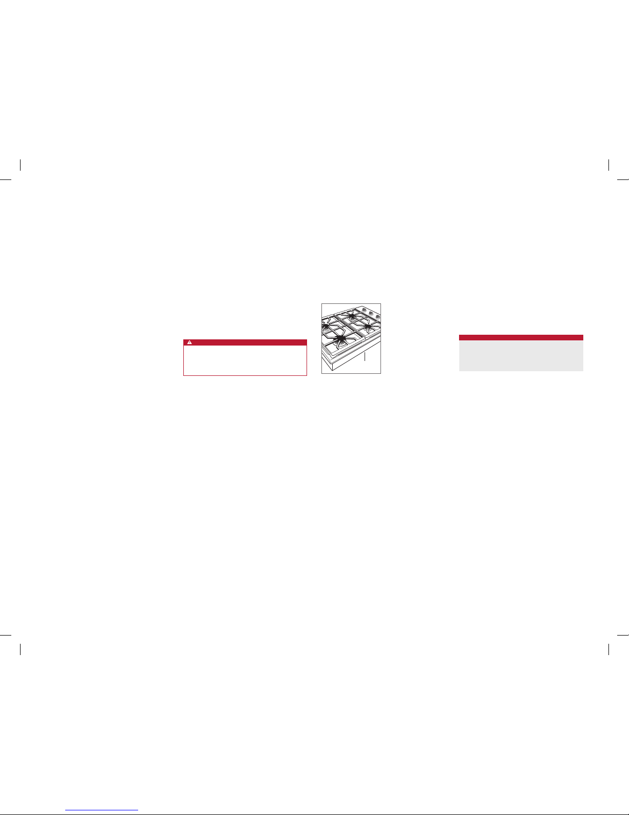
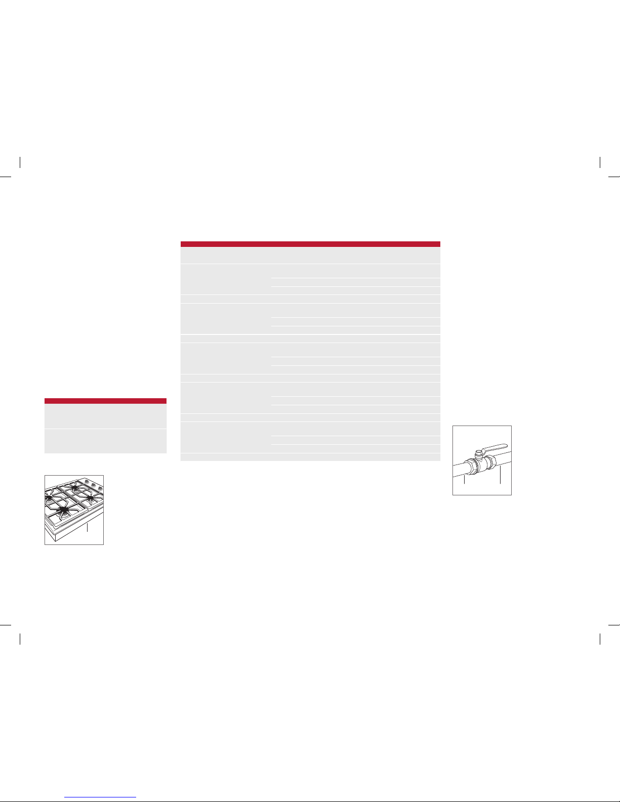
Product Information
Important product information including the model and
serial number are listed on the product rating plate. The
rating plate is located on the bottom of the cooktop. Refer
to the illustration below.
If service is necessary, contact Wolf factory certied service
with the model and serial number.
Important Note
To ensure this product is installed and operated as safely
and efciently as possible, take note of the following types
of highlighted information throughout this guide:
IMPORTANT NOTE highlights information that is especially
important.
CAUTION indicates a situation where minor injury or product
damage may occur if instructions are not followed.
WARNING states a hazard that may cause serious injury or
death if precautions are not followed.
IMPORTANT NOTE: Save these instructions for the local
electrical inspector.
WARNING
This appliance shall be installed in accordance with the
regulations in force and only used in a well ventilated
space. Read the instructions before installing or using
this appliance.
Rating plate location.
RATING PLATE
Installation Requirements
If a cooktop is being installed above an oven, a minimum
of 6 mm is required between units. A minimum 140 mm is
required from the bottom of the cooktop to combustible
materials.
Electrical
Installation must comply with all applicable electrical codes.
Locate the electrical supply as shown in the illustrations
on page 4. A separate circuit, servicing only this appliance
is required. A ground fault circuit interrupter (GFCI) is not
recommended and may cause interruption of operation.
ELECTRICAL REQUIREMENTS
GAS COOKTOP
Electrical Supply grounded (earthed)
220-240 V AC, 50/60 Hz
Service 10 amp dedicated circuit
Receptacle grounding-type (earthed)
IMPORTANT NOTE: Connection of this appliance should be
through a fused connection unit or a suitable isolator, which
complies with national and local safety regulations. The
on/off switch should be easily accessible after the appliance has been installed. If the switch is not accessible after
installation (depending on country) an additional means of
disconnection must be provided for all poles of the power
supply. When switched off there must be an all pole contact
gap of 3 mm in the isolator switch. This 3 mm contact disconnect gap must apply to any isolator switch, fuses and/or
relays according to EN60335.
WF Intl GCooktops IG MultiLang 824551A 10-13.indd 2 2/19/14 12:08 PM
wolfappliance.com | 3
SPECIFICATIONS
Gas Supply
Installation must conform with local codes and ordinances.
Locate the gas supply as shown in the illustrations on
page 4.
The cooktop is equipped for use with natural or liquid propane (LP) gas. The product rating plate has information on
the type of gas that should be used. For rating plate location, refer to the illustration below. If this information does
not agree with the type of gas available, check with the local
gas supplier.
Prior to installation, ensure that the local distribution conditions (nature of the gas and gas pressure) and the adjustment of the appliance are compatible. The adjustment
conditions for this appliance are stated on the label (or
rating plate). The data plate can be found on the underside
of the cooktop.
This appliance is not connected to a combustion products evacuation device. It shall be installed and connected
in accordance with current installation regulations. Particular attention shall be given to the relevant requirements
regarding ventilation.
GAS SUPPLY REQUIREMENTS
NATURAL GAS
Gas Supply Pressure 12.5 mb
Min Line Pressure 17.5 mb
Max Pressure to Regulator 100 mb
LP GAS
Gas Supply Pressure 25 mb
Min Line Pressure 27.4 mb
Max Pressure to Regulator 100 mb
GAS RATING
MODEL
TOTAL HEAT
OUTPUT
GAS
UNITS
APPLIANCE
CATEGORY
TYPES AND
PRESSURE (mbar) COUNTRY OF DESTINATION
ICBGC152T/S 6.2 kW
I2H G20 at 20
AT, BG, CR, CZ, DK, EE, FI, GR, HR, HU, IS, IE, IT, LV, LT,
NO, PT, RO, SK, SI, ES, SE, CH, TR, GB
I2E G20 at 20 DE, LU, PL
I2E+ G20 at 20/25 BE, FR
ICBCG152T/S/LP 1594 g/h I3P G31 at 37 FI, CR, GR, IE, HR, LU, NL, PL, SK, SI, ES, CH, TR, GB
ICBCG304T/S 14.2 kW
I2H G20 at 20
AT, BG, CR, CZ, DK, EE, FI, GR, HR, HU, IS, IE, IT, LV, LT,
NO, PT, RO, SK, SI, ES, SE, CH, TR, GB
I2E G20 at 20 DE, LU, PL
I2E+ G20 at 20/25 BE, FR
ICBCG304T/S/LP 3651 g/h I3P G31 at 37 FI, CR, GR, IE, HR, LU, NL, PL, SK, SI, ES, CH, TR, GB
ICBCG304P/S 14.2 kW
I2H G20 at 20
AT, BG, CR, CZ, DK, EE, FI, GR, HR, HU, IS, IE, IT, LV, LT,
NO, PT, RO, SK, SI, ES, SE, CH, TR, GB
I2E G20 at 20 DE, LU, PL
I2E+ G20 at 20/25 BE, FR
ICBCG304P/S/LP 3651 g/h I3P G31 at 37 FI, CR, GR, IE, HR, LU, NL, PL, SK, SI, ES, CH, TR, GB
ICBCG365T/S 16.9 kW
I2H G20 at 20
AT, BG, CR, CZ, DK, EE, FI, GR, HR, HU, IS, IE, IT, LV, LT,
NO, PT, RO, SK, SI, ES, SE, CH, TR, GB
I2E G20 at 20 DE, LU, PL
I2E+ G20 at 20/25 BE, FR
ICBCG365T/S/LP 4345 g/h I3P G31 at 37 FI, CR, GR, IE, HR, LU, NL, PL, SK, SI, ES, CH, TR, GB
ICBCG365P/S 16.9 kW
I2H G20 at 20
AT, BG, CR, CZ, DK, EE, FI, GR, HR, HU, IS, IE, IT, LV, LT,
NO, PT, RO, SK, SI, ES, SE, CH, TR, GB
I2E G20 at 20 DE, LU, PL
I2E+ G20 at 20/25 BE, FR
ICBCG365P/S/LP 4345 g/h I3P G31 at 37 FI, CR, GR, IE, HR, LU, NL, PL, SK, SI, ES, CH, TR, GB
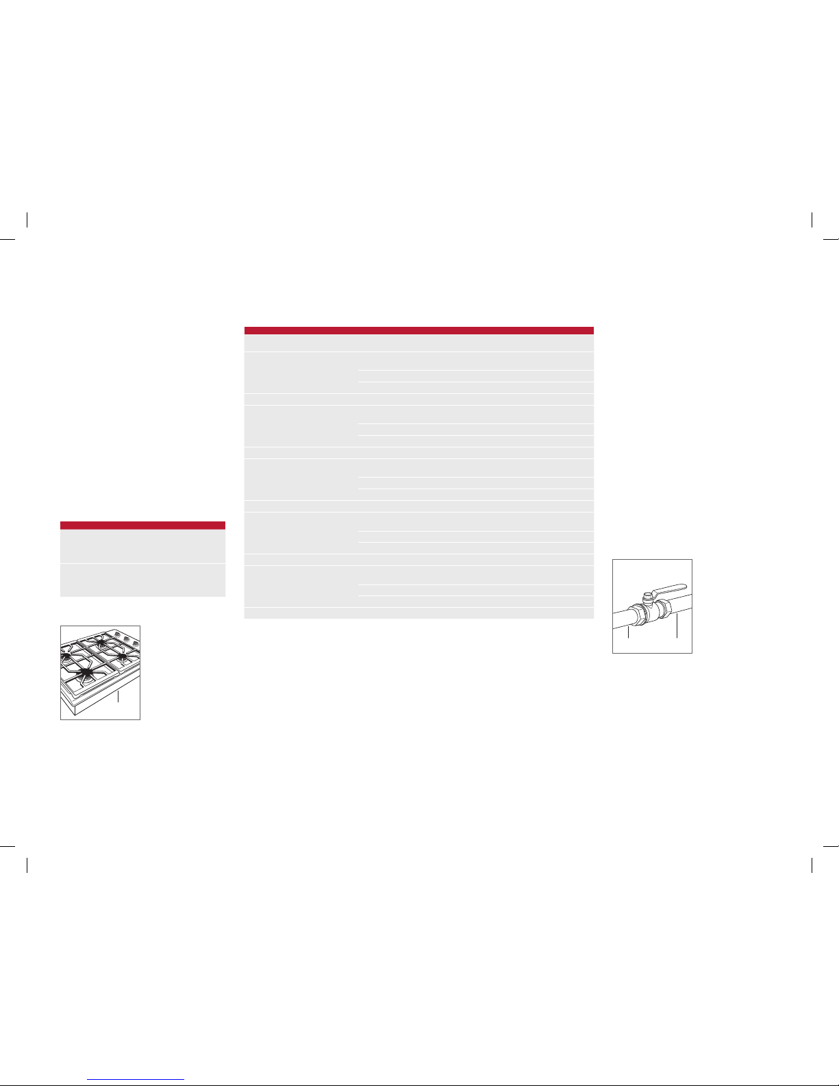
The cooktop must be connected to a regulated gas supply.
The supply line must be equipped with an approved external
gas shut-off valve located near the cooktop in an accessible
location. Do not block access to the shut-off valve. Refer to
the illustration below.
A gas supply line of 19 mm rigid pipe must be provided to
the cooktop. If local codes permit, a certied, .9 m long,
13 mm or 19 mm ID exible metal appliance connector is
recommended to connect the units 1/2" NPT (or ISO 7/1-14)
male inlet to the gas supply line. Pipe joint compounds, suitable for use with natural or LP gas should be used.
The appliance and its shut-off valve must be disconnected
from the gas supply piping system during any pressure
testing of the system at test pressures in excess of 100
mbar. The appliance must be isolated from the gas supply
piping system by closing its individual manual shut-off valve
during any pressure testing of the system at test pressures
equal to or less than 100 mbar.
Wolf natural gas cooktops will function up to 3124 m in
altitude without adjustment and LP gas cooktops will function up to 2621 m. If the installation exceeds these elevations, contact your authorized Wolf dealer for a high altitude
conversion kit.
SHUT-OFF VALVE
OPEN POSITION
GAS SUPPLYTO APPLIANCE
Gas shut-off valve.
Rating plate location.
RATING PLATE
WF Intl GCooktops IG MultiLang 824551A 10-13.indd 3 2/19/14 12:08 PM

4 | English
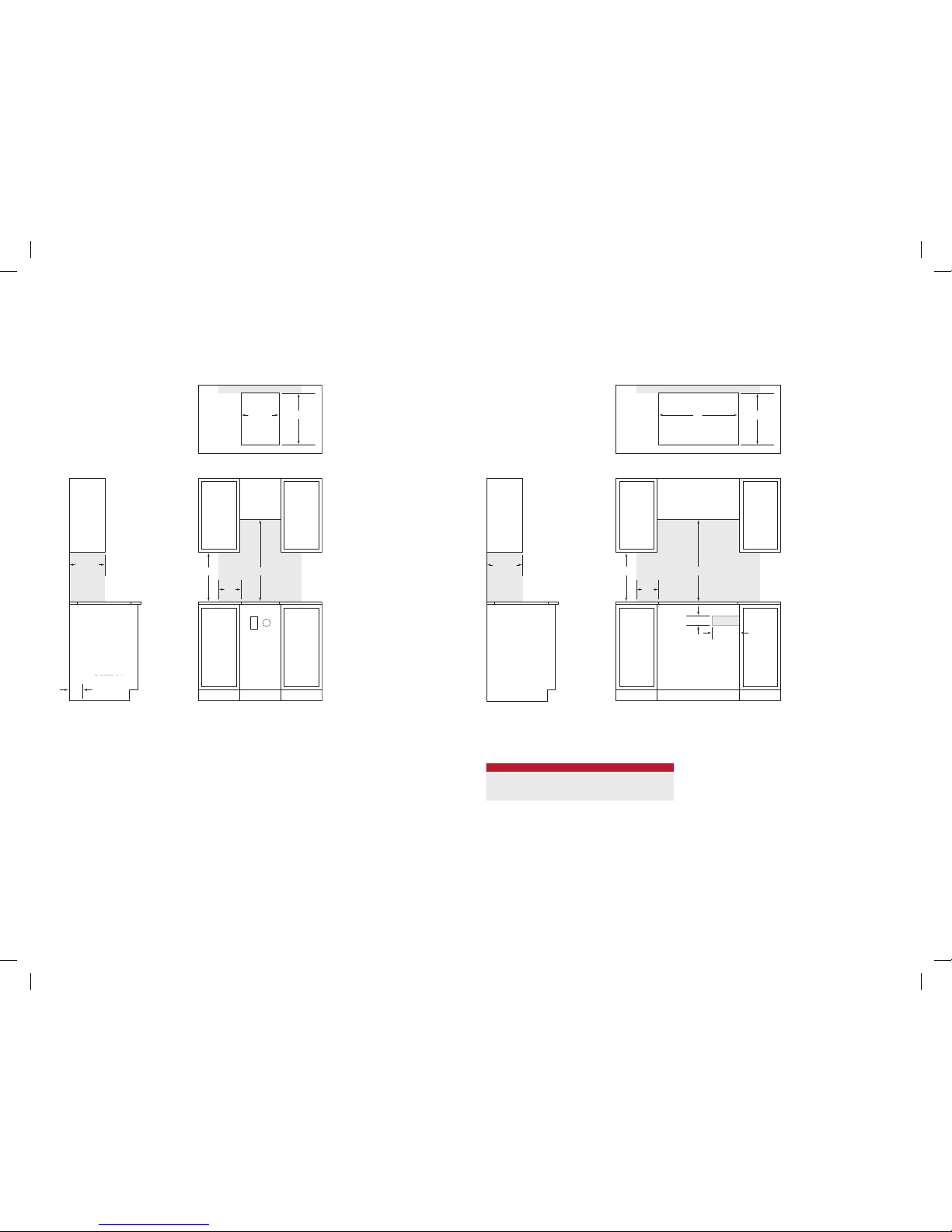
SPECIFICATIONS
762 mm and 914 mm Gas Cooktop
STANDARD INSTALLATION
254 mm
102 mm
89 mm
FRONT VIEW
SIDE
VIEW
COUNTERTOP CUT-OUT
NO
TE: Shaded area above countertop indicates minimum clearance to combustible surfaces,
combus
tible materials cannot be located within this area.
El
ectrical and gas supply location only applies to installations with built-in oven.
762 mm
W
WIDTH
330 mm
457 mm
229
mm
495 mm
64 mm
64 mm
E G
CUT-OUT WIDTH
MODEL W
762 mm Cooktop 737 mm
914 mm Cooktop 889 mm
FRONT VIEWSIDE VIEW
COUNTERTOP CUT-OUT
NOTE: Shaded area above countertop indicates minimum clearance to combustible surfaces,
combustible materials cannot be located within this area.
330 mm
457 mm
178
mm
E G
127
mm
ELECTRICAL
AND GAS FLOOR
LOCATION
762 mm
356 mm
495 mm
64 mm
64 mm
381 mm Gas Cooktop
STANDARD INSTALLATION
WF Intl GCooktops IG MultiLang 824551A 10-13.indd 4 2/19/14 12:08 PM
wolfappliance.com | 5
Wolf, Wolf & Design, Wolf Gourmet, W & Design and the color red as applied to knobs are registered trademarks and service marks of Wolf Appliance, Inc. Sub-Zero, Sub-Zero & Design, Dual Refrigeration, Constant Care, The Living Kitchen, Great American Kitchens The Fine Art of Kitchen Design, and Ingredients are registered trademarks and service marks of Sub-Zero,
Inc. (collectively, the “Company Marks.”) All other trademarks or registered trademarks are property of their respective owners in the United States and other countries.
Cooktop Installation
Remove cooktop and components from the shipping
package and recycle packing materials.
Lower the cooktop into the countertop cut-out. Center
cooktop in the opening with the front edge aligned parallel
to the front edge of the countertop. Using a pencil, outline
the rear edge of the cooktop on the countertop. Remove
cooktop.
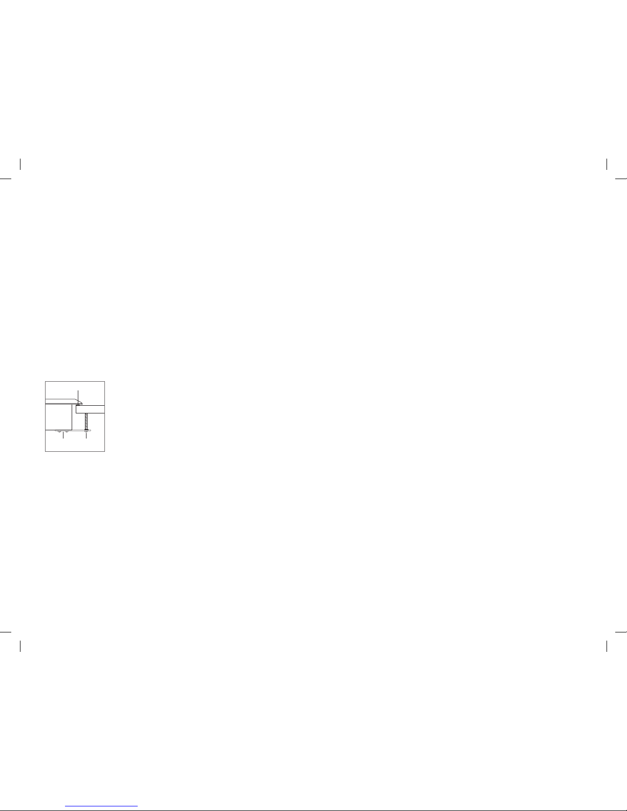
Apply the foam strip provided, to the perimeter of the countertop opening. Refer to the illustration below. Do not seal
the cooktop to the countertop.
Insert the cooktop into the opening. Verify the cooktop is
aligned with the front edge of the countertop.
Attach the brackets provided, to the bottom of the unit.
Insert the 89 mm clamping screws into the brackets. Use a
screwdriver to tighten clamping screws against the bottom
of the countertop. Do not overtighten screws. Refer to the
illustration below.
INSTALLATION
Gas Supply Connection
All connections to the gas piping must be wrench-tightened.
Do not overtighten or allow pipes to turn when tightening.
If a exible metal connector is being used, verify it is not
kinked, then attach the gas supply line to the regulator on
the cooktop. Open the valve and check for leaks by placing
a liquid detergent solution onto all gas connections. Bubbles
around connections indicate a gas leak. If a leak appears,
close the shut-off valve and adjust connections.
Troubleshooting
IMPORTANT NOTE: If the cooktop does not operate prop-
erly, follow these troubleshooting steps:
• Verify electrical power is supplied to the cooktop.
• Verify the gas supply shut-off valve is in the open
position.
• If the cooktop does not operate properly, contact Wolf
factory certied service. Do not attempt to repair the
cooktop. Wolf is not responsible for service required to
correct a faulty installation.
FOAM STRIP
COUNTERTOP
BRACKET
CLAMPING
SCREW
Cooktop installation.
WF Intl GCooktops IG MultiLang 824551A 10-13.indd 5 2/19/14 12:08 PM
2 | Español
PLACAS DE GAS
Contenido
2 Placas de gas
3 Especicaciones
5 Instalación
5 Localización y solución de problemas
Las características y especicaciones están sujetas a cambios sin previo aviso. Visite wolfappliance.com/specs para
obtener la información más actualizada.
Información sobre el producto
En la placa de datos del producto encontrará información
importante, incluyendo el modelo y el número de serie. La
placa de datos está ubicada en la parte inferior del aparato.
Consulte la siguiente ilustración.
Si necesita ayuda, póngase en contacto con el servicio de
asistencia técnica autorizado de Wolf con el modelo y el
número de serie.
Nota importante:
Para garantizar que este producto se instala y funciona de
la forma más ecaz y segura posible, tenga en cuenta la
información que se destaca en esta guía:
Cuando aparece NOTA IMPORTANTE, se resalta información
que resulta especialmente importante.
PRECAUCIÓN indica una situación en la que se pueden
sufrir heridas leves o provocar daños al producto si no se
siguen las instrucciones.
AVISO indica el peligro de que se produzcan heridas graves
o incluso la muerte si no se respetan las precauciones.
NOTA IMPORTANTE: guarde estas instrucciones para el
inspector local.
AVISO
Este aparato debe instalarse de acuerdo con las normativas vigentes y solo puede ser utilizado en un lugar
que esté bien ventilado. Lea las instrucciones antes de
instalar o utilizar este aparato.
Ubicación de la placa de datos.
PLACA DE DATOS
Requisitos de instalación
Si la placa se va a instalar sobre un horno, es necesario
dejar un espacio mínimo de 6 mm entre las unidades.
Asimismo, es necesario dejar un mínimo de 140 mm de la
parte superior de la placa a los materiales combustibles.
Potencia
La instalación debe cumplir con toda la normativa local
aplicable en materia de electricidad.
Ubique la toma eléctrica tal como se muestra en las
ilustraciones de la página 4. Se necesita un circuito
independiente para esta unidad. No se recomienda utilizar
un interruptor de circuito de fallos de toma de tierra (GFCI),
ya que puede interrumpir el funcionamiento de la unidad.
REQUISITOS ELÉCTRICOS
PLACA DE GAS
Suministro eléctrico Conectado a tierra
220-240 V CA, 50/60 Hz
Servicio Circuito dedicado de 10 amperios
Enchufe Con toma de tierra
NOTA IMPORTANTE: la conexión de este aparato debe reali-
zarse a una unidad de conexión con fusibles o a un aislador
adecuado, que cumple con las normativas de seguridad
nacionales y locales. El interruptor de encendido/apagado
debe encontrarse en un lugar accesible después de haber
instalado el aparato. Si no es posible acceder al interruptor
después de la instalación (según el país), se deberá brindar
un medio de desconexión adicional para todos los polos
de la alimentación eléctrica. Al estar desconectado, deberá
existir una separación de contacto entre todos los polos
de 3 mm en el interruptor del aislador. Esta separación de
3 mm de desconexión de los contactos deberá aplicarse a
cualquier interruptor, fusibles o relés del aislador según la
norma EN60335.
WF Intl GCooktops IG MultiLang 824551A 10-13.indd 2 2/19/14 12:08 PM
wolfappliance.com | 3
ESPECIFICACIONES
Suministro de gas
La instalación debe cumplir las ordenanzas y normativas
nacionales.
Ubique la toma de gas tal como se muestra en las ilustraciones de la página 4.
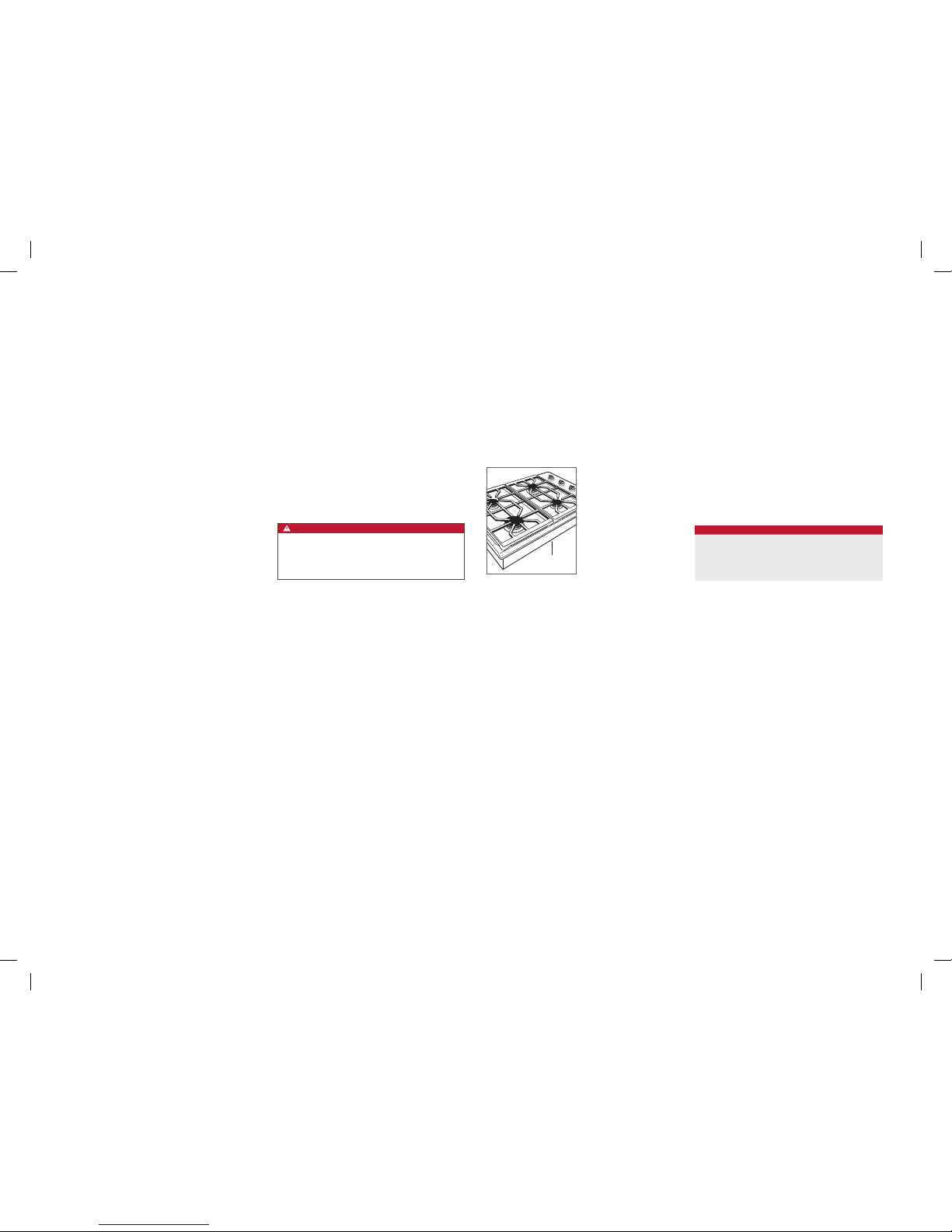
La placa de gas está equipada para usarse con gas natural
o gas propano líquido (GPL). Podrá encontrar información
sobre el tipo de gas que debería utilizar en la placa de datos
del producto. Consulte la siguiente ilustración para ver la
ubicación de la placa. Si esta información no coincide con
el tipo de gas que tiene disponible, póngase en contacto
con su proveedor de gas.
Antes de llevar a cabo la instalación, asegúrese de que las
condiciones de distribución locales (tipo y presión del gas)
y el ajuste del aparato son compatibles. Las condiciones
de ajuste de este aparato se especican en la etiqueta (o
en la placa de datos del producto). La placa de datos está
ubicada en la parte inferior del aparato.
Este aparato no está conectado a ningún dispositivo de
evacuación de productos de combustión. El aparato debe
instalarse y conectarse siguiendo las normativas de instalación vigentes. Debe prestar especial atención a los requisitos relevantes correspondientes a la ventilación.
REQUISITOS DEL SUMINISTRO DE GAS
GAS NATURAL
Presión del suministro de gas 12,5 mb
Presión mínima 17,5 mb
Presión máxima al regulador 100 mb
GAS LP
Presión del suministro de gas 25 mb
Presión mínima 27,4 mb
Presión máxima al regulador 100 mb
CLASIFICACIÓN DEL GAS
MODELO
PRODUCCIÓN
DE CALOR
TOTAL
UNIDADES
DE GAS
CATEGORÍA
DEL APARATO
TIPOS Y PRESIÓN
(mbar) PAÍS DE DESTINO
ICBGC152T/S 6,2 kW
I2H G20 a 20
AT, BG, CR, CZ, DK, EE, FI, GR, HR, HU, IS, IE, IT, LV,
LT, NO, PT, RO, SK, SI, ES, SE, CH, TR, GB
I2E G20 a 20 DE, LU, PL
I2E+ G20 a 20/25 BE, FR
ICBCG152T/S/LP 1594 g/h I3P G31 a 37 FI, CR, GR, IE, HR, LU, NL, PL, SK, SI, ES, CH, TR, GB
ICBCG304T/S 14,2 kW
I2H G20 a 20
AT, BG, CR, CZ, DK, EE, FI, GR, HR, HU, IS, IE, IT, LV,
LT, NO, PT, RO, SK, SI, ES, SE, CH, TR, GB
I2E G20 a 20 DE, LU, PL
I2E+ G20 a 20/25 BE, FR
ICBCG304T/S/LP 3651 g/h I3P G31 a 37 FI, CR, GR, IE, HR, LU, NL, PL, SK, SI, ES, CH, TR, GB
ICBCG304P/S 14,2 kW
I2H G20 a 20
AT, BG, CR, CZ, DK, EE, FI, GR, HR, HU, IS, IE, IT, LV,
LT, NO, PT, RO, SK, SI, ES, SE, CH, TR, GB
I2E G20 a 20 DE, LU, PL
I2E+ G20 a 20/25 BE, FR
ICBCG304P/S/LP 3651 g/h I3P G31 a 37 FI, CR, GR, IE, HR, LU, NL, PL, SK, SI, ES, CH, TR, GB
ICBCG365T/S 16,9 kW
I2H G20 a 20
AT, BG, CR, CZ, DK, EE, FI, GR, HR, HU, IS, IE, IT, LV,
LT, NO, PT, RO, SK, SI, ES, SE, CH, TR, GB
I2E G20 a 20 DE, LU, PL
I2E+ G20 a 20/25 BE, FR
ICBCG365T/S/LP 4345 g/h I3P G31 a 37 FI, CR, GR, IE, HR, LU, NL, PL, SK, SI, ES, CH, TR, GB
ICBCG365P/S 16,9 kW
I2H G20 a 20
AT, BG, CR, CZ, DK, EE, FI, GR, HR, HU, IS, IE, IT, LV,
LT, NO, PT, RO, SK, SI, ES, SE, CH, TR, GB
I2E G20 a 20 DE, LU, PL
I2E+ G20 a 20/25 BE, FR
ICBCG365P/S/LP 4345 g/h I3P G31 a 37 FI, CR, GR, IE, HR, LU, NL, PL, SK, SI, ES, CH, TR, GB
La placa debe conectarse a un suministro de gas regulado.
El suministro de gas debe estar equipado con una válvula
de cierre externa de gas homologada situada en un lugar
accesible, cerca de la placa. No obstruya el acceso a la
válvula de cierre. Consulte la siguiente ilustración.
Debe conectar la placa a un suministro de gas con una
tubería rígida de 19 mm. Si las normativas locales lo permiten, se recomienda utilizar un conector metálico exible
certicado de 0,9 mm y 13 mm o 19 mm de diámetro
interno para conectar la entrada macho 1/2" NPT (o ISO
7/1-14) de las unidades al suministro de gas. Debe utilizar
una pasta de recubrimiento para tuberías que sea adecuada
para que se pueda utilizar con gas LP o natural.
El aparato y su válvula de cierra deben estar desconectados del sistema de suministro de gas durante cualquier
prueba de la presión del sistema que supere los 100 mbar.
El aparato debe aislarse del sistema de suministro de gas
cerrando su válvula manual de cierre individual durante
cualquier prueba de la presión del sistema que sea igual o
inferior a 100 mbar.
Las placas de gas natural Wolf funcionarán en hasta 3124 m
de altitud sin necesidad de ajuste y las placas de gas LP, en
hasta 2621 m. Si la instalación supera estas cifras, póngase en contacto con su distribuidor Wolf autorizado para
obtener un kit de conversión para altitudes elevadas.
Ubicación de la placa de datos.
PLACA DE DATOS
SHUT-OFF VALVE
OPEN POSITION
GAS SUPPLYTO APPLIANCE
Válvula de cierre del gas.
SUMINISTRO
DE GAS
AL APARATO
POSICIÓN ABIERTA DE
LA VÁLVULA DE CIERRE
WF Intl GCooktops IG MultiLang 824551A 10-13.indd 3 2/19/14 12:08 PM
4 | Español
ESPECIFICACIONES
Placa de gas de 762 mm y 914 mm
INSTALACIÓN ESTÁNDAR
254 mm
102 mm
89 mm
FRONT VIEW
SIDE
VIEW
COUNTERTOP CUT-OUT
NO
TE: Shaded area above countertop indicates minimum clearance to combustible surfaces,
combus
tible materials cannot be located within this area.
El
ectrical and gas supply location only applies to installations with built-in oven.
762 mm
W
WIDTH
330 mm
457 mm
229
mm
495 mm
64 mm
64 mm
E G
ANCHURA DEL CORTE
MODELO Anch.
Placa de 762 mm 737 mm
Placa de 914 mm 889 mm
FRONT VIEWSIDE VIEW
COUNTERTOP CUT-OUT
NOTE: Shaded area above countertop indicates minimum clearance to combustible surfaces,
combustible materials cannot be located within this area.
330 mm
457 mm
178
mm
E G
127
mm
ELECTRICAL
AND GAS FLOOR
LOCATION
762 mm
356 mm
495 mm
64 mm
64 mm
Placa de gas de 381 mm
INSTALACIÓN ESTÁNDAR
CORTE DE LA ENCIMERA
ANCHO
A
VISTA FRONTAL
VISTA LATERAL
CORTE DE LA ENCIMERA
VISTA FRONTALVISTA LATERAL
NOTA: el área sombreada sobre la encimera indica la distancia mínima a supercies combustibles, no puede
haber materiales combustibles en esta área
NOTA: el área sombreada sobre la encimera indica la distancia mínima a supercies combustibles, no puede
haber materiales combustibles en esta área.
La ubicación de la toma eléctrica y de gas solo se aplica a una instalación con horno empotrable.
UBICACIÓN DEL
SUELO ELÉCTRICO
Y DEL GAS
WF Intl GCooktops IG MultiLang 824551A 10-13.indd 4 2/19/14 12:08 PM
 Loading...