

Wolf SO30F/S, SO36U/S, SO36U/P, SO36U/B, SO30U/S Technical & Service Manual
...
Technical Service Manual
© WOLF APPLIANCE COMPANY, LLC 2005 ALL RIGHTS RESERVED JOB AID #806372 • (Revision B - 2005)
WWaallll OOvveenn SSeerriieess
WWaallll OOvveenn SSeerriieess
Wall Oven-2 & Wall Oven-3


General Information
WWaallll OOvveenn SSeerriieess
WWaallll OOvveenn SSeerriieess
1-1
SECTION 1
GENERAL INFORMATION
General Information
WWaallll OOvveenn SSeerriieess
WWaallll OOvveenn SSeerriieess
1-2
INTRODUCTION
This Wolf Wall Oven Series Technical Service Manual, Part #806372, has been compiled to provide the most recent
technical service information about the Wolf Wall Ovens produced after serial number 11100847. This information
will enable the service technician to troubleshoot and diagnose malfunctions, perform necessary repairs and return a
Wolf Wall Oven Series to proper operational condition.
The service technician should read the complete instructions contained in this service manual before initiating any
repairs on a Wolf Appliance.
NOTE: Refer to the Wall Oven-2 Series Service Parts Manual #806373 for part numbers and exploded views for
units produced prior to serial number 16000000 and Wall Oven-3 Series Service Parts Manual #807041 for units
produced after serial number 16000000 .
IMPORTANT SAFETY INFORMATION
Below are the Product Safety Labels used in this manual. The "Signal Words" used are WARNING and
CAUTION.
Please note that these safety labels are placed in areas
where awareness of personal safety and product safety
should be taken and lists the precautions to be taken
when the signal word is observed.
TECHNICAL ASSISTANCE
If you should have any questions regarding a Wolf
appliance and/or this manual, please contact:
Wolf Appliance Company, LLC
ATTN: Service Department
P.O. Box 44988
Madison, WI 53744-4988
Customer Service
Phone #: (800) 332 - 9513
Technical Assistance
Phone #: (800) 919 - 8324
Parts / Warranty Claims
Phone #: (800) 332 - 9513
Customer Service E-Mail Address
customerservice@wolfappliance.com
Customer Service & Technical Assistance
Facsimile #: (608) 441 - 5887
Parts / Warranty Claims
Facsimile #: (608) 441 - 5886
Office Hours:
7:00 AM to 7:00 PM Central Standard Time
Monday through Friday
This manual is designed to be used by Authorized Service Personnel only. Wolf Appliance Company, LLC.
assumes no responsibility for any repairs made to Wolf appliances by anyone other than Authorized
Service Technicians.
INDICATES THAT HAZARDOUS OR UNSAFE PRACTICES COULD RESULT IN SEVERE PERSONAL
INJURY OR DEATH
Indicates that hazardous or unsafe practices could
result in minor personal injury or product and/or
property damage
In addition, please pay attention to the signal word
“NOTE”, which highlights especially important information within each section.
The information and images are the copyright property of Wolf Appliance Company, LLC, an affiliate of Sub-Zero
Freezer Company, Inc. Neither this manual nor any information or images contained herein may be copied or used
in whole or in part without the express written permission of Wolf Appliance Company, LLC, an affiliate of Sub-Zero
Freezer Company, Inc. © Wolf Appliance Company, LLC all rights reserved.

1-3
General Information
WWaallll OOvveenn SSeerriieess
WWaallll OOvveenn SSeerriieess
TABLE OF CONTENTS
Page #
Section 1 - General Information
Introduction......................................................................... 1-2
Important Safety Information.............................................. 1-2
Technical Assistance.......................................................... 1-2
Table of Contents............................................................... 1-3
Table of Contents.............................................................. 1-4
Warranty Information......................................................... 1-5
Serial Tag Location............................................................ 1-5
Model Number Key.. ......................................................... 1-6
Model Configurations......................................................... 1-7
Model Configurations......................................................... 1-8
Oven Features................................................................... 1-9
Section 2 -Inst
allation Information
Electrical Requirements..................................................... 2-2
Minimum Wire Size............................................................ 2-2
Oven Installation................................................................ 2-3
Trim Installation.................................................................. 2-3
Wall Oven Dimensions....................................................... 2-4
Cabinet Cutout Dimensions............................................... 2-5
SO30........................................................................... 2-5
SO36........................................................................... 2-6
DO30........................................................................... 2-7
Side-by-Side................................................................ 2-8
Section 3 - Electronic Control System
Electronic Control Terminology and Component
Descriptions........................................................................ 3-2
Unique Electronic Control Input Operations....................... 3-3
Field Option Mode........................................................... 3-3
User Preference Offset................................................... 3-3
Temperature Display Preference.................................... 3-3
Clock Display Preference.................................................3-3
Sabbath Feature............................................................. 3-4
Time Cook Feature......................................................... 3-5
Delayed Start Feature..................................................... 3-6
Temperature Probe Mode............................................... 3-7
USDA Internal Temperature
Recommendations Chart................................................ 3-7
Self-Clean Mode............................................................. 3-8
Electronic Control Input Operations................................... 3-9
Bake Mode..................................................................... 3-9
Convection Mode...........................................................3-10
Convection Bake Mode................................................. 3-11
Broil Mode..................................................................... 3-12
Convection Broil Mode................................................. 3-13
Roast Mode.................................................................. 3-14
Convection Roast Mode................................................ 3-15
Bake Stone Mode.......................................................... 3-16
Dehydrate Feature.........................................................3-17
Proof Feature.......................................................... 3-18
Panel Lock..................................................................... 3-19
Time of Day Clock......................................................... 3-19
Diagnostics Mode............................................................. 3-19
Double Wall Oven Keyboard......................................... 3-19
Single Wall Oven Keyboard...........................................3-19
Page #
Section 3 - Electronic Control System (Continued)
Initiating Diagnostic Mode..............................................3-20
Possible Error Indicators............................................... 3-21
Testing The Oven Relay Board..................................... 3-24
Element Testing............................................................. 3-24
Fan and Motor Testing................................................. 3-25
RTD Testing................................................................... 3-25
Temperature Probe Testing............................................3-25
Section 4 - Component
Access and Removal
Important Warnings............................................................ 4-2
Control Panel Components................................................ 4-3
Control Panel Assembly ................................................ 4-3
Control Panel Drive Motor............................................... 4-3
C-Channel Top and Bottom............................................ 4-4
Switch Actuator and Plunger........................................... 4-4
Components Behind the Control Panel.............................. 4-5
Latch Cover..................................................................... 4-5
Motor Door Lock............................................................. 4-5
Limit Switch.................................................................... 4-5
Oven Control Board........................................................ 4-6
Stepper Motor Control Board......................................... 4-6
Relay Board.................................................................... 4-7
Light Transformer............................................................ 4-7
Light Fuse....................................................................... 4-7
Upper Cooling Fan......................................................... 4-8
Terminal Block................................................................ 4-8
Oven Cavity Components.................................................. 4-9
Left and Right Rack Guide.............................................. 4-9
Oven Lights..................................................................... 4-9
Convection Baffle Plate.................................................. 4-9
Probe Cover and Probe Switch......................................4-10
Temperature Sensor.......................................................4-10
Convection Fan..............................................................4-11
Broil Element and Broil Pan...........................................4-11
Smoke Catalyst.............................................................. 4-11
Bake Stone ....................................................................4-12
Oven Door Components....................................................4-13
Oven Door......................................................................4-13
Door Adjustments...........................................................4-13
Door Gasket...................................................................4-13
Outer Door Skin.............................................................4-13
Glass Pack.....................................................................4-14
Hinge..............................................................................4-14
Hydraulic Hinge............................................................. 4-14
Components Behind the Back Panel............................... 4-15
Back Panel.................................................................... 4-15
Divider Channels........................................................... 4-15
Lower Cooling Fan........................................................ 4-15
Bake Element................................................................ 4-15
Oven Side Components................................................... 4-16
Channel Venting............................................................ 4-16
Hinge Pocket................................................................. 4-16
Enclosure.......................................................................4-16
Insulation........................................................................4-16

General Information
WWaallll OOvveenn SSeerriieess
WWaallll OOvveenn SSeerriieess
1-4
Section 5 -Troubleshooting Guide
General Troubleshooting Guide Layout................................5-2
Troubleshooting Guide Table of Contents............................5-2
Initiating Diagnostic Mode.....................................................5-3
Error Code Chart..................................................................5-4
Testing The Oven Relay Board............................................5-5
Element Testing....................................................................5-5
Ohm Testing Elements at the Relay Board.......................5-5
Fans and Motors...............................................................5-6
RTD Testing..........................................................................5-6
Probe Testing........................................................................5-6
Troubleshooting Guides........................................................5-7
Troubleshooting Flow Chart..................................................5-9
Head Assembly Doesn’t Rotate Flow Chart.......................5-10
Section 6 -T
echnical Data
Technical Data Chart............................................................6-2
Operation Time Chart...........................................................6-3
Section 7 -Wiring Diagrams
DO30 Wiring Diagram...........................................................7-2
DO30 Schematic...................................................................7-3
SO30 - SO36 Wiring Diagram..............................................7-4
SO30 - SO36 Schematic......................................................7-5
SO30 Schematic (SWS 16000000)......................................7-6
DO30 Schematic (SWS 16000000)......................................7-7
1-5
General Information
WWaallll OOvveenn SSeerriieess
WWaallll OOvveenn SSeerriieess
WARRANTY INFORMATION
This page contains a summary of the 2 & 5 Year Warranty that is supplied with every Wolf product, followed by
details and notes about the warranties.
TWO & FIVE YEAR Warranty Summary
• Two year TOTAL PRODUCT warranty, *parts and labor.
• Limited Parts Only Warranty for the 3rd through 5th year on the following parts only:
Electric heating elements
Electronic Control Boards
Warranty Details:
The warranty applies only to products installed for normal residential use. The warranty applies only to product
installed in the United States or Canada.
Warranty Notes:
• All warranties begin at the time of the unit’s initial installation.
• All Warranty and Service information collected by Wolf Appliance Company, LLC. is arranged and
stored under the unit serial number and/or the customer’s name. Please note that Wolf Appliance
Company LLC. requests that you have the model serial number available whenever contacting the
factory or parts distributor.
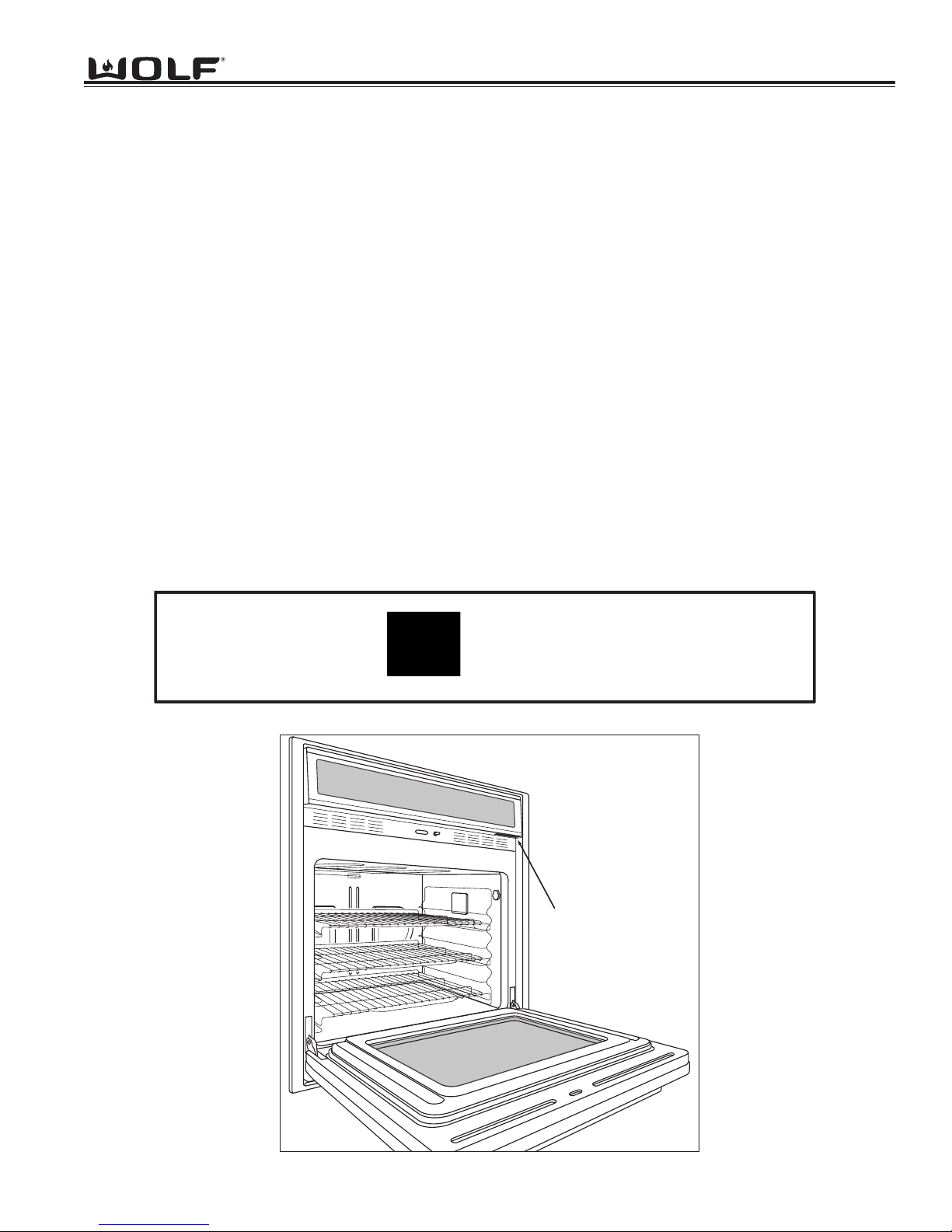
• See Figure 1-1 for serial tag layout.
• See Figure 1-2 for serial tag location.
Figure 1-1. Typical Serial Tag Layout
Figure 1-2. The serial tag is located underneath the control panel.
Wolf Appliance Company, LLC
FITCHBURG, WI
WALL OVEN
FOR HOUSEHOLD USE ONLY
X.X
VOLTS :
Hz :
60
MODEL# : XXXXXX-X
"DO NOT IMMERSE IN WATER" "NE PAS PLONGE DANS L'EAU"
KW :
120/208
120/240
Serial Tag Location
X.X
3 WIRE
SERIAL# : XXXXXXXX
-2

General Information
WWaallll OOvveenn SSeerriieess
WWaallll OOvveenn SSeerriieess
1-6
MODEL NUMBER KEY
Refer to this key for an example of the model numbers.
Model: SO 30 F / S
Product Type
Size
Fuel
Feature (If Applicable)
Finish
Product T
ype
SO Single Oven
DO Double Oven
CT Cooktop
Size
30 30 - inch wide unit
36 36 - inch wide unit
Fuel
E Electric
Oven Door
F Framed
U Unframed
Finish
S Classic Stainless Steel
P Platinum Stainless Steel
B Carbon Stainless Steel
1-7
General Information
WWaallll OOvveenn SSeerriieess
WWaallll OOvveenn SSeerriieess
MODEL CONFIGURATIONS
30” Single Oven Framed
Model Number Description
SO30F/S Single Oven 30” Framed Stainless
Model Number Description
SO30U/S Single Oven 30” Unframed Stainless
SO30U/P Single Oven 30” Unframed Platinum
SO30U/B Single Oven 30” Unframed Carbon
Single Ovens
36” Single Oven Unframed
Model Number Description
SO36U/S Single Oven 36” Unframed Stainless
SO36U/P Single Oven 36” Unframed Platinum
SO36U/B Single Oven 36” Unframed Carbon
General Information
WWaallll OOvveenn SSeerriieess
WWaallll OOvveenn SSeerriieess
1-8
30” Double Oven Framed
Double Ovens
30” Double Oven Unframed
Model Number Description
DO30F/S Double Oven 30” Framed Stainless
Model Number Description
DO30U/S Double Oven 30” Unframed Stainless
DO30U/P Double Oven 30” Unframed Platinum
DO30U/B Double Oven 30” Unframed Carbon
1-9
General Information
WWaallll OOvveenn SSeerriieess
WWaallll OOvveenn SSeerriieess
• Two door styles
Traditional Framed (30”)
Contemporary Unframed (30” & 36”)
• Framed door finish
Classic Stainless Steel
• Unframed door finishes
Classic Stainless Steel
Platinum Stainless Steel
Carbon Stainless Steel
• Dual Convection Logic Control System
• Rotating Control Panel
• Touch Control Panel
• Door Hinge with Hydraulic Damper System
• Large Viewing Window
• Triple Pane Window
• Dual Halogen Lighting
• Temperature Probe and Receptacle
• Six Level Rack Guide
• Full Extension Bottom Rack
• Hidden Bake Element
• Broil Element
• Bake Mode
• Convection Mode
• Convection Bake Mode
• Broil Mode
• Convection Broil Mode
• Roast Mode
• Convection Roast Mode
• Bake Stone Mode (Bake Stone Optional)
• Dehydrate Feature (Dehydrate Kit Optional)
• Proof Feature
• Self-Clean Mode
• Sabbath Mode
OVEN FEATURES

General Information
WWaallll OOvveenn SSeerriieess
WWaallll OOvveenn SSeerriieess
1-10

WWaallll OOvveenn SSeerriieess
WWaallll OOvveenn SSeerriieess
Installation Information
2-1
SECTION 2
INSTALLATION
INFORMATION
WWaallll OOvveenn SSeerriieess
WWaallll OOvveenn SSeerriieess
Installation Information
2-2
INSTALLATION INFORMATON
This section of the manual covers some of the installation issues a service technician may need to know when servicing a Wolf Wall Oven. If additional information is needed after reviewing this section of the manual, please refer to
the Installation Guide or contact the Wolf Appliance Customer Service Department.
Electrical Requirements:
Single Oven
• 208/220-240 volts AC, 60 Hertz, 30 Ampere fused electrical supply.
Double Oven
• 208/220-240 volts AC, 60 Hertz, 50 Ampere fused electrical supply.
Minimum Wire Size:
• L1, L2 and Ground: 10 AWG
• Neutral: 12 AWG
This appliance must be properly grounded. This appliance is equipped with a 60” conduit consisting of two insulated
hot lead copper conductors, one insulated neutral copper conductor and one uninsulated ground copper conductor.
THIS APPLIANCE MUST BE PROPERLY GROUNDED AT ALL TIMES WHEN ELECTRICAL POWER IS
APPLIED.
DO NOT GROUND THE APPLIANCE WITH THE NEUTRAL (WHITE) HOUSE SUPPLY WIRE. A SEPERATE
GROUND WIRE MUST BE UTILIZED.
IF ALUMINUM HOUSE SUPPLY WIRING IS UTILIZED, SPLICE THE APPLIANCE COPPER WIRE TO THE ALUMINUM HOUSE WIRING USING SPECIAL CONNECTORS DESIGNED AND CERTIFIED FOR JOINING COPPER
AND ALUMINUM. FOLLOW THE CONNECTORS MANUFACTURERS RECOMMENDED PROCEDURE CAREFULLY. IMPROPER CONNECTION CAN RESULT IN A FIRE HAZARD.
2-3
WWaallll OOvveenn SSeerriieess
WWaallll OOvveenn SSeerriieess
Installation Information
s
"
8-32
ew
Sc
"-18x
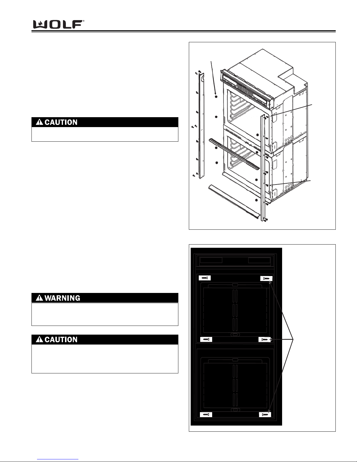
Figure 2-1. Trim Installation
Figure 2-2. Cabinet Mounting Screws
Oven Installation
Use the upper edge of the cavity opening and the bottom of the oven chassis side as gripping points to lift
the oven into the cabinet cutout. Slide the oven into the
recessed area until the unit is approximately six inches
from being fully installed. This will allow for installation
of the oven trim kit.
NOTE: The oven door(s) may be removed to reduce
the weight of the oven when lifting into cabinet opening.
Trim Installation
Attach the left and right side trim to the bottom and middle trim prior to installing on the oven.
(See Figure 2-1).
NOTE: The middle trim is for double ovens only.
Peel off the adhesive backing on the flat washers.
Attach the flat washers centered over the holes of the
raised sides of the oven cavity frame.
NOTE: Four washers for single oven and eight washers for double oven.
Install the trim to the oven using the screws provided in
the trim kit. Now, locate the mounting holes found on
the sides of the oven trim. Then, use a drill with a 1/16”
drill bit and drill four pilot holes for the cabinet mounting
screws. Install the mounting screws through the oven
side trim and into the cabinet. (See figure 2-2).
NOTE: Do not overtighten the mounting screws.
FAILURE TO INSTALL THE MOUNTING SCREWS
MAY RESULT IN MOVEMENT OR TIPPING OF THE
OVEN DURING USE.
Do not block the oven air exhaust located at the
bottom of the oven. Blocking the exhaust may
result in cabinet damage and poor baking performance.
Do not lift or carry the oven door(s) by the door
handle.
Flat Washer
x3/4
r
1/2
Mounting Screw
6-18x1"
WWaallll OOvveenn SSeerriieess
WWaallll OOvveenn SSeerriieess
Installation Information
2-4
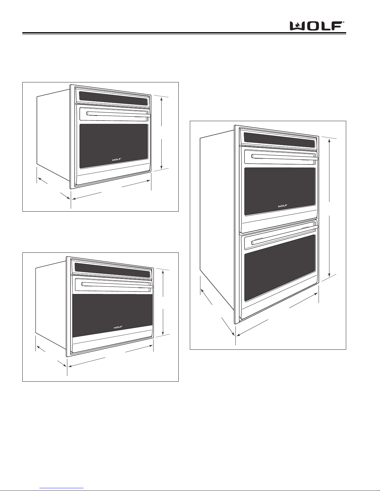
Figure 2-5. 30” Double Oven Overall Dimensions
Figure 2-3. 30” Single Oven Overall Dimensions
Figure 2-4. 36” Single Oven Overall Dimensions
WALL OVEN DIMENSIONS
271/2"
(699mm)
24"
(610
mm)
24"
mm)
(610
297/8"
mm)
(759
355/8"
(905mm)
243/8"
(619mm)
50"
(1269mm)
24"
(610
mm)
297/8"
mm)
(759
2-5
WWaallll OOvveenn SSeerriieess
WWaallll OOvveenn SSeerriieess
Installation Information
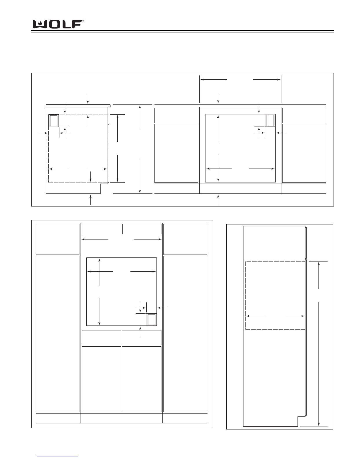
CABINET CUTOUT DIMENSIONS
Single 30 Inch Wall Oven
Figure 2-6. Undercounter Cutout Dimensions and Electrical Placement
Figure 2-7. Front Cutout Dimensions and Electrical Placement Figure 2-8. Side View
NOTE: Dimensions in parentheses are in millimeters.
33/4" min
(95)
5"
E
(127)
(691)
36" (914)
STANDARD
FLOOR T O
COUNTER
HEIGHT
4"
(102
)
ELECTRICAL
LOCATION IN
ADJACENT RIGHT
SIDE CABINET
24" min
(610)
43/4" min (121)
273/16"
RECOMMENDED CABINET WIDTH
33" (838)
30" min (762)
RECOMMENDED CABINET WIDTH
273/16"
43/4" min (121)
30" min (762)
33/4" min (95)
(691)
33" (838)
(102)
281/2"
(724)
5"
E
(127)
4"
NOTE: Dimensions in
parentheses are in
millimeters.
281/2"
(724)
273/16"
(691)
4"
(102)
5"
(127)
E
RIGHT SIDE
CABINET VIEW
24" min
(610)
67" max
(1702)
WWaallll OOvveenn SSeerriieess
WWaallll OOvveenn SSeerriieess
Installation Information
2-6
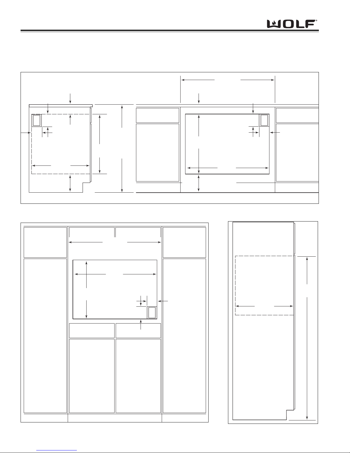
CABINET CUTOUT DIMENSIONS
Single 36 Inch Wall Oven
Figure 2-9. Undercounter Cutout Dimensions and Electrical Placement
Figure 2-10. Front Cutout Dimensions and Electrical Placement Figure 2-11. Side View
NOTE: Dimensions in parentheses are in millimeters.
33/4" min
(95)
5"
E
(127)
(611)
36" (914)
STANDARD
FLOOR T O
COUNTER
HEIGHT
4"
(102
)
ADJACENT RIGHT
73/4" (197) rec
(121) min
43/4"
ELECTRICAL
LOCATION IN
SIDE CABINET
24" min
(610)
241/16"
RECOMMENDED CABINET WIDTH
39" (991)
36" min (914)
RECOMMENDED CABINET WIDTH
241/16"
(611)
39" (991)
36" min (914)
33/4"
min (95)
341/2"
(876 )
73/4" (197) rec
43/4" (121) min
5"
(127)
4"
(102)
Dimensions in
NOTE:
parentheses are in
millimeters.
E
341/2"
(876 )
241/16"
(611)
4"
(102)
5"
(127)
24" min
E
RIGHT SIDE
CABINET VIEW
(610)
67" max
(1702)
2-7
WWaallll OOvveenn SSeerriieess
WWaallll OOvveenn SSeerriieess
Installation Information
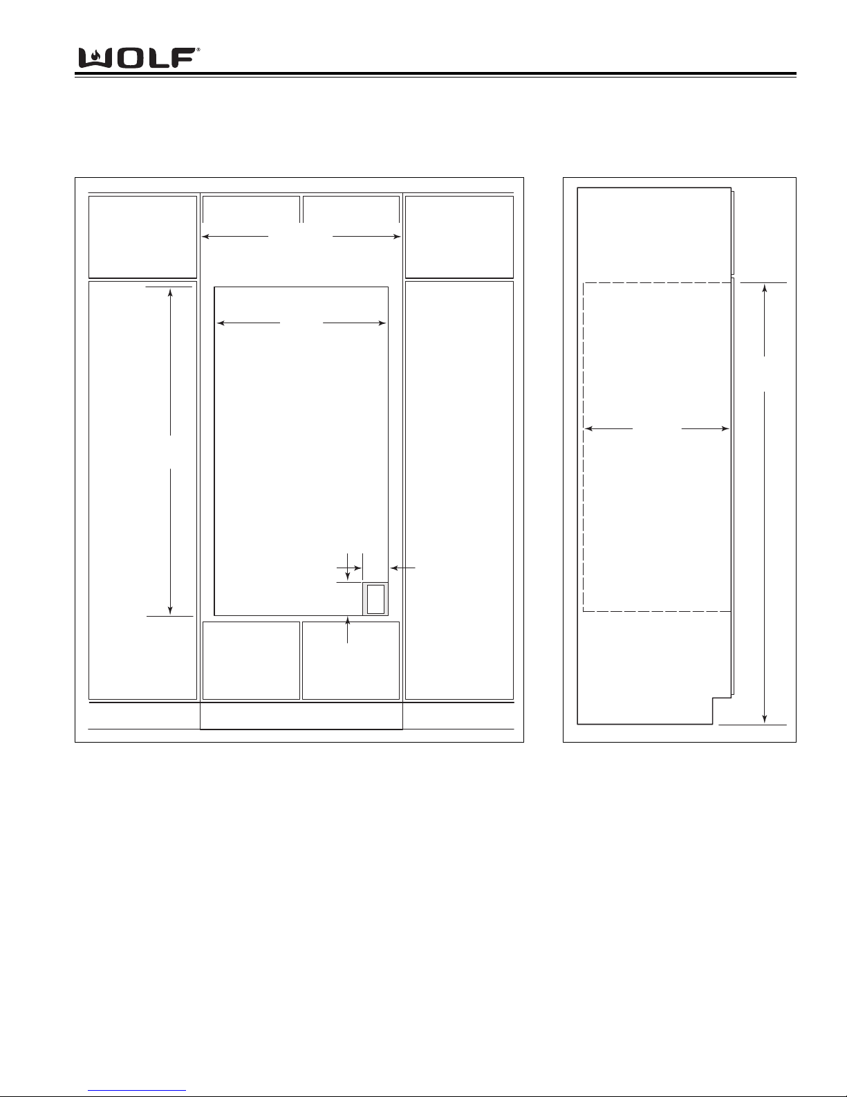
CABINET CUTOUT DIMENSIONS
Double 30 Inch Wall Oven
Figure 2-12. Front Cutout Dimensions and Electrical Placement
Figure 2-13. Side View
33" (838)
RECOMMENDED CABINET WIDTH
30" min (762)
281/2"
(724)
495/8"
(1260)
NOTE: Dimensions in
parentheses are in
millimeters.
67" max
(1702)
24" min
(610)
4"
(102)
5"
E
(127)
RIGHT SIDE
CABINET VIEW
WWaallll OOvveenn SSeerriieess
WWaallll OOvveenn SSeerriieess
Installation Information
2-8
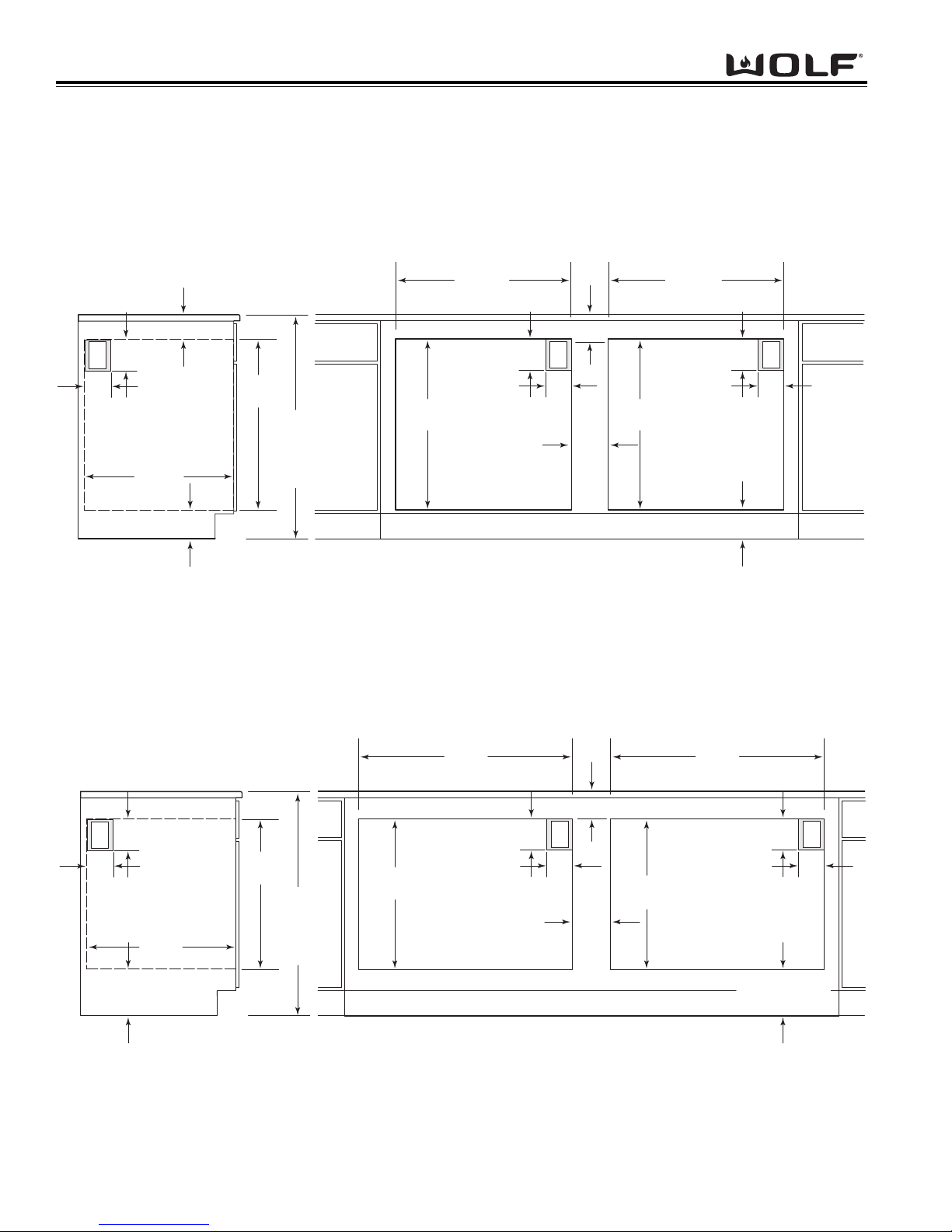
CABINET CUTOUT DIMENSIONS
Side-by-Side Wall Oven
Figure 2-14. Undercounter Cutout Dimensions and Electrical Placement for SO30
Figure 2-15. Undercounter Cutout Dimensions and Electrical Placement for SO36
NOTE: Dimensions in parentheses are in millimeters.
33/4" min
(95)
5"
E
(127)
4"
(102
)
ELECTRICAL
LOCATION IN
ADJACENT RIGHT
SIDE CABINET
24" min
(610)
43/4" min (121)
273/16"
(691)
STANDARD
FLOOR TO
COUNTER
36" (914)
HEIGHT
281/2"
(724)
30" OVEN CUT-OUT
273/16"
(691)
4"
(102)
5"
(127)
33/4"
E
min (95)
71/2"
(191)
281/2"
(724)
30" OVEN CUT-OUT
273/16"
(691)
4"
(102)
43/4"
5"
(127)
min (121)
E
NOTE: Dimensions in parentheses are in millimeters.
min (95)
5"
E
(127)
4"
(102
73/4" (197) rec
43/4" (121) min
ELECTRICAL
LOCATION IN
)
ADJACENT RIGHT
SIDE CABINET
24" min
(610)
241/16"
(611)
STANDARD
FLOOR TO
COUNTER
36" (914)
HEIGHT
241/16"
(611)
341/2"
(876)
36" OVEN CUT
-OUT
4"
(102)
5"
(127)
341/2"
(876)
36" OVEN CUT-OUT
33/4" min (95)33/4"
5"
E
4"
(102)
73/4" (197) rec
43/4"
71/2"
(191)
241/16"
(611)
(127)
(121) min
E

WWaallll OOvveenn SSeerriieess
WWaallll OOvveenn SSeerriieess
Electronic Control System
3-1
SECTION 3
ELECTRONIC CONTROL
SYSTEM

WWaallll OOvveenn SSeerriieess
WWaallll OOvveenn SSeerriieess
Electronic Control System
3-2
ELECTRONIC CONTROL TERMINOLOGY & COMPONENT DESCRIPTIONS
All Wolf wall ovens utilize an electronic control system. The electronic control system monitors, regulates and controls a variety of functions. The control system also displays error codes to identify possible problems with the unit.
The table below defines some of the basic electronic control system terminology and describes some of the electronic system components. An understanding of the following information is needed in order to comprehend the
input operations and functions of the electronic control system.
T
erm / Component Definition / Description
Oven Controller.......................................The printed circuit board containing the microprocessor and logic inputs
which communicates with the oven display, keyboard, stepper motor control
board.
Relay Board............................................The printed circuit board containing the microprocessor, relays and electrical
connections which control and monitor functions and operations of the unit.
Oven Display...........................................A vacuum fluorescent display which shows oven temperature, cooking
modes, error codes, cook times and stop time.
Stepper Motor Control Board..................The printed circuit board containing a transformer and logic control to drive
the stepper motor.
Control Panel Assembly..........................The head assembly containing the oven display(s) and keyboard.
Relays.....................................................The electrical components on the relay board that switch other components
in the unit ON and OFF when instructed to do so by the microprocessor.
Microprocessor........................................An electrical component on the control board which receives electrical sig-
nals from other components, processes that information, then sends an
electrical signal to the relays on the board to open or close, and other components in the unit to switch on or off.
Keyboard.................................................An assembly of glass and mylar which connects into the upper oven display.
Error Codes.............................................Number or word description which appears on the oven display if the unit
experiences specific problems related to electrical signals supplied by the
electrical components.
MDL.........................................................Motor door latch assembly which incorporates the latch motor drive, unlatch
switch, latch switch and door switch.
RTD.........................................................The oven(s) temperature sensing device.
DLB...........................................................A component on the relay board which is a relay that connects and discon-
nects the L2 line to the elements when energized by logic from the oven
controller.
WWaallll OOvveenn SSeerriieess
WWaallll OOvveenn SSeerriieess
Electronic Control System
3-3
UNIQUE ELECTRONIC CONTROL INPUT OPERATIONS
The following few pages illustrate electronic control input operations that you would not expect a customer to perform everyday.
The input operations described are: Field Option Mode, Sabbath Mode, Delayed Start Mode, Probe Mode and Self-Clean Mode.
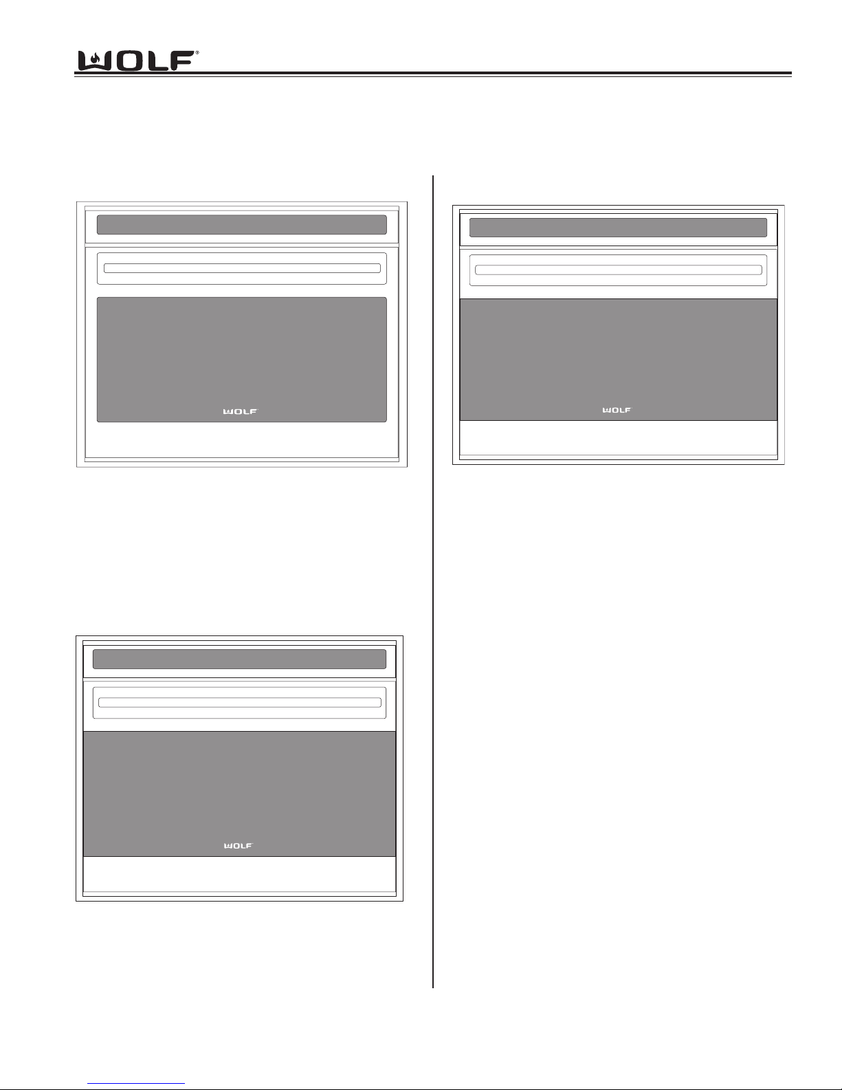
Field Option Mode
Field option mode allows for the user to adjust specific options of the oven controller, such as User Preference Offset (adjusting
temperature ± 35°), Temperature Display Preference (choosing between °F, Fahrenheit or °C, Celsius) and Clock Display
Preference (12 Hour Clock or 24 Hour Clock).
NOTE: Field Option Mode must be entered with the oven(s) turned OFF.
To initiate Field Option Mode, Press and hold the TEMPERATURE key for five seconds.
NOTE: Pressing the CLEAR key will cancel the Field Option Mode.
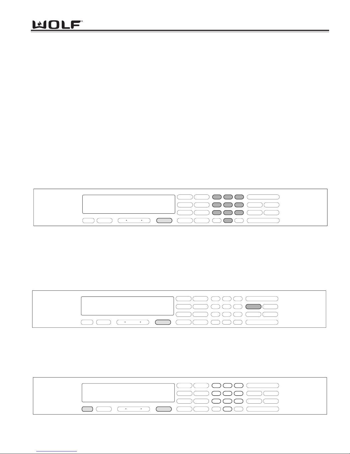
User Preference Offset
This option allows the user to offset a specific oven temperature ±35° in 1°F (Fahrenheit) increments. Once in Field Option
Mode, press the number keys to input the numeric value of the offset and press the TEMPERATURE key to toggle between ±.
The new offset is accepted ten seconds after the last key stroke or by pressing the ENTER key. (See Figure 3-1). Pressing the
CLEAR key will cancel the Field Option Mode.
NOTE: Entering a positive number will increase oven temperature.
NOTE: User Preference Offset will only work for °F (Fahrenheit).
f
Figure 3-1. User Preference Offset. Press and HOLD the TEMPERATURE key for five seconds. Then, press the number
keys to enter a new numeric value up to 35. Now, press the TEMPERATURE key to toggle between ±.
Figure 3-2. Temperature Display Preference. Must be in Field Option Mode. Now, press the COOK TIME key to toggle
between °C and °F.
Temperature Display Preference
This option allows the user to choose how the temperature is displayed, °F (Fahrenheit) or °C (Celsius), and/or back again.
Once in Field Option Mode, press the COOK TIME key to toggle between °C and °F. The new display, °C or °F is accepted ten
seconds after the last key stroke or by pressing the ENTER key. See Figure 3-2. Pressing the CLEAR key will cancel the Field
Option Mode.
c
Figure 3-2.1. Clock Display Preference. Must be in Field Option Mode. Now, press the CLOCK key to toggle between 12
hour and 24 hour clock.
Clock Display Preference
This option allows the user to choose how the clock is displayed, 12 hour or 24 hour, and/or back again. Once in Field Option
Mode, press the CLOCK key to toggle between 12 hour or 24 hour clock. The new display is accepted ten seconds after the last
key stroke or by pressing the ENTER key. See Figure 3-2.1. Pressing the CLEAR key will cancel the Field Option Mode.
f
ON/OFF
CLEAR
LIGHT
3
COOK TIME
STOP TIME
PANEL LOCK
SELF CLEAN
ON/OFF
PROBE
3 00
CLOCK
CONV. BAKE
BAKE
.
.
12 hr clock
OFF ON
TIMER
OVEN
0
set upo
TEMPERATURE
°
ROAST
CONV. ROAST
BROIL
CONV. BROIL
BAKE STONE
CONVECTION
1
4
7
ENTER
2
56
89
0
ON/OFF
CLEAR
LIGHT
3
COOK TIME
STOP TIME
PANEL LOCK
SELF CLEAN
ON/OFF
PROBE
3 00
CLOCK
CONV. BAKE
BAKE
.
.
TIMER
12 hr clock
OFF
OVEN
ON
TEMPERATURE
°
ROAST
CONV. ROAST
BROIL
CONV. BROIL
BAKE STONE
CONVECTION
1
4
7
ENTER
2
56
89
0
.
.
3 00
CLOCK
TIMER
24 hr clock
OFF ON
OVEN
CONV. BAKE
BAKE
°
ROAST
BROIL
BAKE STONE
CONV. ROAST
CONV. BROIL
CONVECTION
0
set upo
TEMPERATURE
1
4
7
ENTER
2
3
56
89
CLEAR
0
LIGHT
COOK TIME
SELF CLEAN
PROBE
ON/OFF
STOP TIME
PANEL LOCK
ON/OFF
WWaallll OOvveenn SSeerriieess
WWaallll OOvveenn SSeerriieess
Electronic Control System
3-4
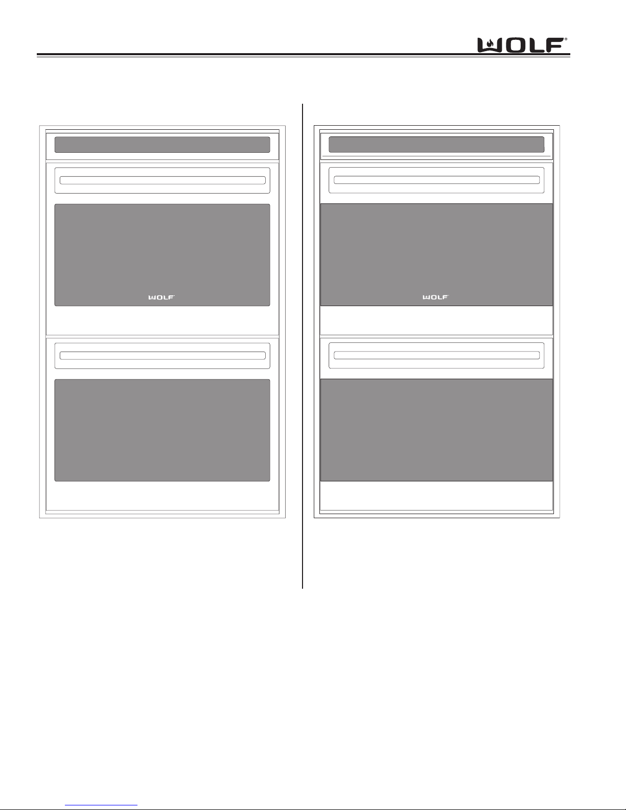
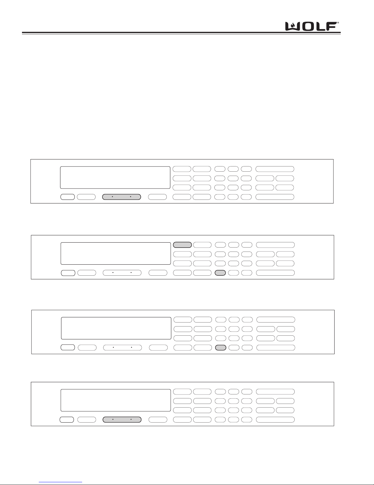
Sabbath Feature
Sabbath Feature was incorporated into the electronic control system for the observance of certain religious holidays.
Once Sabbath Mode has been entered, all of the oven functions have been disabled except the OFF key.
To initiate Sabbath feature, the oven must be OFF. Press UPPER or LOWER OVEN ON key for a double oven or
OVEN ON key for a single oven. (See Figure 3-3). Turn on the interior oven lights by pressing the OVEN LIGHT
ON key (Optional). Press the BAKE or ROAST key. A preset temperature of 350° will be shown in the display. To
change temperature, immediately enter another temperature using the number keys, then press ENTER. (See
Figure 3-4). Now, press and hold the ENTER key for five seconds. The oven will chime twice and the word SABBATH appears in the display window. (See Figure 3-5). Repeat these steps above for each oven(s).
To exit the Sabbath Mode, press the UPPER or LOWER OVEN OFF key or the OVEN OFF key, depending on the
model. (See Figure 3-6).
NOTE: The oven(s) will remain on until the Sabbath Mode is cancelled.
Figure 3-4. Press the BAKE key. A preset temperature of 350°F will be shown in the display.
To change temperature, immediately enter another temperature using the number keys. Then, press ENTER.
Figure 3-6. To exit Sabbath Mode. Press the Oven OFF key.
For Double Ovens select either Upper Oven OFF key or Lower Oven OFF key.
Figure 3-3. To initiate Sabbath Mode, the oven must be OFF. Press Oven ON key.
For Double Ovens select either Upper Oven ON key or Lower Oven ON key.
f
f
f
f
f
Figure 3-5. Now, press and HOLD THE ENTER key for 5 seconds.
The oven will chime twice and the word Sabbath appears in the display.
ON/OFF
STOP TIME
PANEL LOCK
ON/OFF
3 00
CLOCK
CONV. BAKE
BAKE
.
.
select mode
TIMER
OFF ON
OVEN
TEMPERATURE
ROAST
BROIL
BAKE STONE
CONV. ROAST
CONV. BROIL
CONVECTION
1
4
7
ENTER
2
56
89
CLEAR
0
LIGHT
3
COOK TIME
SELF CLEAN
PROBE
ON/OFF
STOP TIME
PANEL LOCK
ON/OFF
3 00
OVEN ON
CLOCK
CONV. BAKE
.
.
bake
OFF ON
TIMER
OVEN
TEMPERATURE
350
setpoint
TEMPERATURE
°
BAKE
ROAST
BROIL
BAKE STONE
CONV. ROAST
CONV. BROIL
CONVECTION
1
4
7
ENTER
2
56
89
CLEAR
0
LIGHT
3
COOK TIME
SELF CLEAN
PROBE
ON/OFF
STOP TIME
PANEL LOCK
ON/OFF
3 00
CLOCK
.
.
OVEN ON
TIMER
sabbath setpoint
OFF ON
OVEN
350
TEMPERATURE
TEMPERATURE
CONV. BAKE
BAKE
°
ROAST
CONV. ROAST
BROIL
CONV. BROIL
BAKE STONE
CONVECTION
1
4
7
ENTER
2
56
89
CLEAR
0
LIGHT
3
COOK TIME
SELF CLEAN
PROBE
.
.
3 00
OFF ON
CLOCK
TIMER
OVEN
TEMPERATURE
BAKE STONE
BAKE
ROAST
BROIL
CONV. BAKE
CONV. ROAST
CONV. BROIL
CONVECTION
1
4
7
ENTER
2
56
89
CLEAR
0
LIGHT
3
COOK TIME
SELF CLEAN
PROBE
ON/OFF
STOP TIME
PANEL LOCK
ON/OFF
WWaallll OOvveenn SSeerriieess
WWaallll OOvveenn SSeerriieess
Electronic Control System
3-5
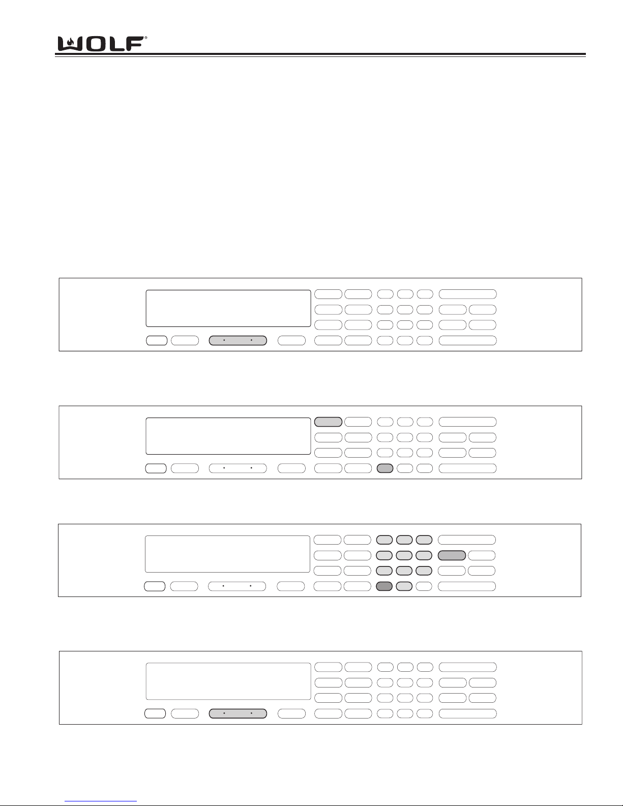
Time Cook Feature
Time Cook Feature controls the automatic timing of the oven(s) ON and OFF function by setting the cooking time to
start immediately and turn off when the desired cooking is complete. To accomplish time cook, the time of day clock
is used and therefore the correct time must be displayed prior to programming.
To initiate Time Cook, the oven must be OFF. First press the Oven ON key. (See Figure 3-7). For Double Ovens
press the Upper Oven ON key or the Lower Oven ON key. Now, press a desired cooking mode (example Bake
Mode). A preset temperature of 350°F is shown in the display. To change the temperature from 350°F, immediately
enter another temperature using the number keys. (See Figure 3-8). Then, press the COOK TIME key. Then, enter
the hours/minutes desired for cooking. The oven(s) will start heating after a five second delay or by pressing the
ENTER key. (See Figure 3-9). To exit TIME COOK feature, press the Oven OFF key. (See Figure 3-10). For the
Double Oven, press the Upper Oven OFF key or the Lower Oven Off key.
NOTE: The oven should always be preheated in this mode. The oven will chime after the oven reaches preheat
temperature.
Figure 3-8. Press a desired Cooking Mode. (Example: Bake Mode). A preset temperature of 350°F will be shown in the
display
. To change temperature, immediately enter another temperature using the number keys.
Figure 3-10. To exit the Cook Time Feature. Press the Oven OFF key.
For Double Ovens select either Upper Oven OFF key or Lower Oven OFF key.
Figure 3-7. To initiate Time Cook Feature, the oven must be OFF. Press Oven ON key.
For Double Ovens select either Upper Oven ON key or Lower Oven ON key.
f
f
f
f
f
Figure 3-9. Now, press the Cook Time key. Now, enter the hours/minutes desired for cooking. The Stop Time will auto-
matically be entered in the display. Then, press the ENTER key. The oven(s) will now start heating and then turn off
when the cooking times has completed.
ON/OFF
CLEAR
LIGHT
3
COOK TIME
STOP TIME
PANEL LOCK
SELF CLEAN
ON/OFF
PROBE
.
.
3 00
CLOCK
TIMER
select mode
OFF ON
OVEN
TEMPERATURE
BAKE
ROAST
BROIL
BAKE STONE
CONV. BAKE
CONV. ROAST
CONV. BROIL
CONVECTION
1
4
7
ENTER
2
56
89
0
ON/OFF
CLOCK
3:00
OVEN ON
TIMER
Bake
OFF ON
OVEN
TEMPERATURE
350
SETPOINT
TEMPERATURE
°
BAKE
ROAST
BROIL
BAKE STONE
CONV. BAKE
CONV. ROAST
CONV. BROIL
CONVECTION
1
4
7
ENTER
2
56
89
0
CLEAR
LIGHT
3
COOK TIME
STOP TIME
PANEL LOCK
SELF CLEAN
ON/OFF
PROBE
ON/OFF
CLOCK
3:00
OVEN ON
TIMER
COOK TIME
MINUTES
HOURS
2:30
bake
OFF ON
OVEN
STOP TIME
HOURS
5:30
MINUTES
TEMPERATURE
350
SETPOINT
TEMPERATURE
°
BAKE
ROAST
BROIL
BAKE STONE
CONV. BAKE
CONV. ROAST
CONV. BROIL
CONVECTION
1
4
7
ENTER
2
56
89
0
CLEAR
LIGHT
3
COOK TIME
STOP TIME
PANEL LOCK
SELF CLEAN
ON/OFF
PROBE
3:00
CLOCK
TIMER
OFF ON
OVEN
TEMPERATURE
BAKE
ROAST
BROIL
BAKE STONE
CONV. BAKE
CONV. ROAST
CONV. BROIL
CONVECTION
1
4
7
ENTER
2
3
56
89
CLEAR
0
COOK TIME
SELF CLEAN
LIGHT
PROBE
ON/OFF
STOP TIME
PANEL LOCK
ON/OFF
 Loading...