

Wolf DF30, DF30-3, DF36-3, DF48-3, DF60-3 Technical & Service Manual
...
Dual Fuel Range
Technical Service Manual
© WOLF APPLIANCE, INC. 2007 ALL RIGHTS RESERVED JOB AID #804710 (Revision H)
DF30 - DF36 - DF48 - DF60
DF30-3 - DF36-3 - DF48-3 - DF60-3
DF30-4 - DF36-4 - DF48-4 - DF60-4


General Information
1-1
DDuuaall FFuueell RRaannggee
SECTION 1
GENERAL INFORMATION

DDuuaall FFuueell RRaannggee
General Information
1-2
TECHNICAL ASSISTANCE
If you should have any questions regarding a Wolf
appliance and/or this manual, please contact:
Wolf Appliance, Inc.
ATTN: Service Department
P.O. Box 44988
Madison, WI 53744-4988
Customer Service & Parts / Warranty Claims
Phone #: (800) 332 - 9513
Technical Assistance
Phone #: (800) 919 - 8324
Customer Service & Technical Assistance
Facsimile #: (608) 441 - 5887
Parts / Warranty Claims
Facsimile #: (608) 441 - 5886
Office Hours:
7:00 AM to 7:00 PM Central Time
Monday through Friday
This manual is designed to be used by Authorized Service Personnel only. Wolf Appliance, Inc. assumes
no responsibility for any repairs made to Wolf appliances by anyone other than Authorized Service
Technicians.
IMPORTANT SAFETY INFORMATION
Below are the Product Safety Labels used in this manual. The "Signal Words" used are WARNING and
CAUTION.
Please note that these safety labels are placed in areas
where awareness of personal safety and product safety
should be taken and lists the precautions to be taken
when the signal word is observed.
INTRODUCTION
This Wolf Dual Fuel Technical Service Manual, Part #804710, has been compiled to provide the most recent technical service information about the Wolf Appliance, Inc., Dual Fuel Ranges. This information will enable the service
technician to troubleshoot and diagnose malfunctions, perform necessary repairs, and return a Wolf Dual Fuel
Range to proper operational condition.
The service technician should read the complete instructions contained in this Technical Service Manual before initiating any repairs on a Wolf Appliance.
* Some information in Section 3 (Operation Information) has been provided by the American Gas Association
and reprinted with AGA’s approval.
NOTE: Refer to the Dual Fuel Service Parts Manual #806375 for part numbers and exploded views for units produced prior to serial number 16000000 and Dual Fuel-3 Service Parts Manual #807040 for units produced after serial number 16000000.
INDICATES THAT HAZARDOUS OR UNSAFE PRACTICES COULD RESULT IN SEVERE PERSONAL
INJURY OR DEATH
Indicates that hazardous or unsafe practices could
result in minor personal injury or product and/or
property damage
In addition, please pay attention to the signal word
“NOTE”, which highlights especially important information within each section.
The information and images are the copyright property of Wolf Appliance, Inc., an affiliate of Sub-Zero, Inc. Neither
this manual nor any information or images contained herein may be copied or used in whole or in part without the
express written permission of Wolf Appliance, Inc., an affiliate of Sub-Zero, Inc. © Wolf Appliance, Inc., all rights
reserved.

General Information
1-3
DDuuaall FFuueell RRaannggee
TABLE OF CONTENTS
Page #
Page #
Section 1 - General Information
Introduction......................................................................... 1-2
Important Safety Information.............................................. 1-2
Technical Assistance.......................................................... 1-2
Table of Contents............................................................... 1-3
Warranty Information......................................................... 1-5
Model Features.................................................................. 1-6
Model Key.......................................................................... 1-7
Model Descriptions............................................................ 1-8
Section 2 - Inst
allation Information
Electrical Requirements..................................................... 2-2
Gas Requirements............................................................. 2-3
Leak Testing....................................................................... 2-4
Installation Dimensions...................................................... 2-5
Unit Leveling...................................................................... 2-6
Section 3 - Operation Information
Theory of Operation........................................................... 3-2
Types of Fuel Gas........................................................... 3-2
Heating Value of Gas...................................................... 3-2
Specific Gravity of Gas................................................... 3-2
Principals of Gas Combustion............................................ 3-2
Requirements for Combustion........................................ 3-3
Chemistry of Combustion............................................... 3-3
Controlled Combustion................................................... 3-3
Total Air........................................................................... 3-3
Limits of Flammability...................................................... 3-3
Incomplete Combustion.................................................. 3-3
Gas Burner Operation..................................................... 3-3
Burner Components (PTS 17000000).................................3-4
Burner Head.................................................................... 3-4
Venturi............................................................................. 3-4
Inner Distribution Ring......................................................3-4
Outer Distribution Ring.................................................... 3-4
Jet Holder........................................................................ 3-4
Gas Orifice...................................................................... 3-4
Burner Components (SWS 17000000)............................... 3-5
Types of Burners................................................................ 3-6
Blue Flame Burners........................................................ 3-6
Infrared Burners.............................................................. 3-6
Operation of The Dual Fuel Range.................................... 3-7
Surface Burners.............................................................. 3-7
Grate Placement............................................................. 3-7
Control Knobs................................................................. 3-7
Burner Lighting................................................................ 3-7
Power Outage..................................................................3-7
Charbroiler....................................................................... 3-8
Charbroiler Operation..................................................... 3-8
Cleaning and Maintenance............................................. 3-9
Charbroiler Cleaning and Maintenance...........................3-10
Griddle Operation............................................................3-10
Griddle Care....................................................................3-10
Time of Day Clock...........................................................3-11
Oven Timer......................................................................3-11
Field Option Mode...........................................................3-11
UPO (User Preference Offset).....................................3-11
Changing Clock to 24 Hours........................................3-11
UPO (User Preference Offset).....................................3-11
Section 3 - Operation Information Cont’d
Field Option Mode..........................................................3-11
Changing Clock to 24 Hours...................................... 3-11
Fahrenheit to Celsius..................................................... 3-11
Cooking Modes..................................................................3-12
Bake Mode.................................................................... 3-12
Bake Stone Mode......................................................... 3-12
Broil Mode..................................................................... 3-13
Convection Mode...........................................................3-13
Convection Bake Mode................................................. 3-14
Convection Broil Mode.................................................. 3-14
Convection Roast Mode................................................ 3-15
Roast mode................................................................... 3-15
Oven Features.................................................................. 3-16
Dehydration Feature...................................................... 3-16
Proof Mode................................................................ 3-16
Proof Feature.................................................................3-16
Delayed Start Feature....................................................3-17
Probe Feature............................................................... 3-17
Sabbath Feature............................................................ 3-18
Self-Clean Feature........................................................ 3-18
Diagnostic Mode............................................................... 3-19
Initiating Diagnostic Mode..............................................3-19
Error Indicators................................................................. 3-20
Testing the Oven Relay Board......................................... 3-21
Element Testing............................................................. 3-21
RTD Testing................................................................... 3-21
Probe Testing.................................................................3-21
Fans and Motors Testing................................................3-22
Section 4 - Component
Access and Removal
Important Warnings and Cautions...................................... 4-2
Surface Burner Components.............................................. 4-3
Surface Burner Grate (PTS 17000000)...........................4-3
Burner Head with Cap (PTS 17000000)..........................4-3
Burner Cap (PTS 17000000)...........................................4-3
Venturi (PTS 17000000)..................................................4-4
Inner Distribution Ring (PTS 17000000)..........................4-4
Igniter (PTS 17000000)................................................... 4-4
Burner Grate and Burner Assembly (SWS 17000000)....4-5
Burner Pan and Trim Moldings (SWS 17000000)............4-5
Burner Pan - 6 Burner (PTS 17000000)........................ 4-6
Burner Pan - 2 Burner (PTS 17000000).........................4-6
Outer Distribution Ring (PTS 17000000).........................4-6
Jet Holder (PTS 17000000)........................................... 4-7
Deflector Shield (PTS 17000000)................................. 4-7
Spark Module (PTS 17000000).................................... 4-7
Burner Support (PTS 17000000).....................................4-7
Surface Burner Orifice (PTS 17000000)......................... 4-7
Orifice Removal (SWS 17000000....................................4-8
Orifice Holder (SWS 17000000)...................................... 4-8
Infrared Charbroiler Components...................................... 4-9
Electrode........................................................................ 4-9
Infrared Burner............................................................... 4-9
IR Orifice........................................................................ 4-9
PTS = Prior to Serial Number
SWS = Starting with Serial Number

DDuuaall FFuueell RRaannggee
General Information
1-4
Page #
Page #
Section 4 - Component Access and Removal Cont’d
Infrared Griddle Components.......................................... 4-10
Grease Tray and Griddle................................................4-10
Thermostat Support Assembly...................................... 4-10
Electrode....................................................................... 4-10
IR WEld Assembly..........................................................4-10
Infrared Burner...............................................................4-10
Infrared Thermostat........................................................4-11
Solenoid.............................................................................4-11
IR Orifice.........................................................................4-11
Bull Nose Components..................................................... 4-12
Burner Knob...................................................................4-12
Burner Knob Bezel.........................................................4-12
Oven Selector Knob...................................................... 4-12
Function Selector Bezel................................................ 4-12
Bull Nose...................................................................... 4-12
Selector Switch............................................................. 4-13
Indicator Light............................................................... 4-13
ECH.............................................................................. 4-13
ECH Adjustment........................................................... 4-13
Components Behind the Bull Nose................................. 4-14
Valve Switch................................................................. 4-14
Burner Valve................................................................. 4-14
Charbroiler Valve.......................................................... 4-14
Griddle Shut-Off............................................................ 4-14
Manifold..........................................................................4-14
Control Board............................................................... 4-15
Relay Board.................................................................. 4-15
Motorized Door Latch................................................... 4-15
Transformer.................................................................. 4-15
Oven Door Components................................................. 4-16
Oven Door.................................................................... 4-16
Door.............................................................................. 4-16
Door Re-Installation...................................................... 4-16
Door Adjustments......................................................... 4-17
Door Gasket................................................................. 4-17
Outer Door Skin Assembly........................................... 4-18
Glass Pack................................................................... 4-18
Hinge............................................................................ 4-18
Hydraulic Hinge............................................................ 4-18
Oven Compartment Components.................................... 4-19
Oven Light.................................................................... 4-19
Convection Baffle Plate................................................ 4-19
Convection Fan Assembly............................................ 4-19
Broil Element and Broil Pan........................................ 4-19
Smoke Catalyst............................................................ 4-19
Temperature Sensor (RTD).......................................... 4-20
Probe Cover and Probe Switch.................................... 4-20
Hidden Bake Element................................................... 4-20
Side and Back Panel Components.................................. 4-21
Outer Side Panel.......................................................... 4-21
Cooling Fan.................................................................. 4-21
Thermo Limiter............................................................. 4-21
Section 5 - Troubleshooting Guide
How to Use the Troubleshooting Guide.............................. 5-2
Diagnostic Mode.............................................................. 5-2
Error Indicators................................................................. 5-2
Field Option Mode............................................................... 5-2
UPO (User Preference Offset)......................................... 5-2
Changing Clock to 24 Hours............................................ 5-2
Fahrenheit to Celsius....................................................... 5-2
Troubleshooting Guide Table of Contents........................... 5-3
General Troubleshooting Guide........................ 5-3 thru 5-10
Error Codes....................................................................... 5-10
ECH Troubleshooting Flow Chart...................................... 5-11
DSI Board Troubleshooting Flow Chart............................. 5-12
Testing the Oven Relay Board.......................................... 5-13
RTD Testing....................................................................... 5-13
Probe Testing.................................................................... 5-13
Fans and Motor Testing..................................................... 5-14
Ohm Testing Elements at Relay Board............................. 5-14
Section 6 - T
echnical Data
Technical Data Chart........................................................... 6-2
Orifice Quick Reference Chart............................................ 6-3
Operation Time Chart.......................................................... 6-4
Cooling Fan Operational Temperatures.............................. 6-4
Preheat Times..................................................................... 6-4
Section 7 - W
iring Diagrams
DF304, DF366, DF364C & DF364G Wiring Diagram......... 7-2
DF30, DF36 Schematic....................................................... 7-3
DF304 Rangetop Harness Diagram.................................... 7-4
DF364G Rangetop Harness Diagram................................. 7-4
DF364C Rangetop Harness Diagram................................. 7-5
DF366 Rangetop Harness Diagram.....................................7-6
DF48 Wiring Diagram...........................................................7-7
DF48 Schematic...................................................................7-8
DF486C Rangetop Harness Diagram..................................7-9
DF486G Rangetop Harness Diagram................................7-10
DF484F Rangetop Harness Diagram................................ 7-11
DF484CG Rangetop Harness Diagram..............................7-12
DF48DC Rangetop Harness Diagram............................... 7-13
DF484DG Rangetop Harness Diagram............................ 7-14
DF60 Schematic................................................................ 7-15
DF60 Wiring Diagram........................................................ 7-16
DF604CF Rangetop Harness Diagram............................. 7-17
DF604GF Rangetop Harness Diagram............................. 7-18
DF606CG Rangetop Harness Diagram..............................7-19
DF606DC Rangetop Harness Diagram............................. 7-20
DF606DG Rangetop Harness Diagram..............................7-21
DF606F Rangetop Harness Diagram.................................7-22
W
iring Diagrams Starting with Serial #16000000
DF304, DF366, DF364C & DF364G Wiring Diagram........7-23
DF30, DF36 Schematic......................................................7-24
DF48 Wiring Diagram.........................................................7-25
DF48 Schematic.................................................................7-26
DF60 Wiring Diagram........................................................ 7-27
DF60 Schematic................................................................ 7-28
General Information
1-5
DDuuaall FFuueell RRaannggee
WARRANTY INFORMATION
This page contains a summary of the 2 & 5 Year Warranty that is supplied with every Wolf product, followed by
details and notes about the warranties.
TWO & FIVE YEAR Warranty Summary
• Two year TOTAL PRODUCT warranty, parts and labor.
• Limited Parts Only Warranty for the 3rd through 5th year on the following parts only:
Electric heating elements
Electronic Control Boards
Warranty Details:
The warranty applies only to products installed for normal residential use. The warranty applies only to product
installed in the United States or Canada.
Warranty Notes:
• All warranties begin at the time of the unit’s initial installation.
• All Warranty and Service information collected by Wolf Appliance, Inc. is arranged and
stored under the unit serial number and/or the customer’s name. Please note that Wolf Appliance, Inc. requests
that you have the model serial number available whenever contacting the factory or parts distributor.
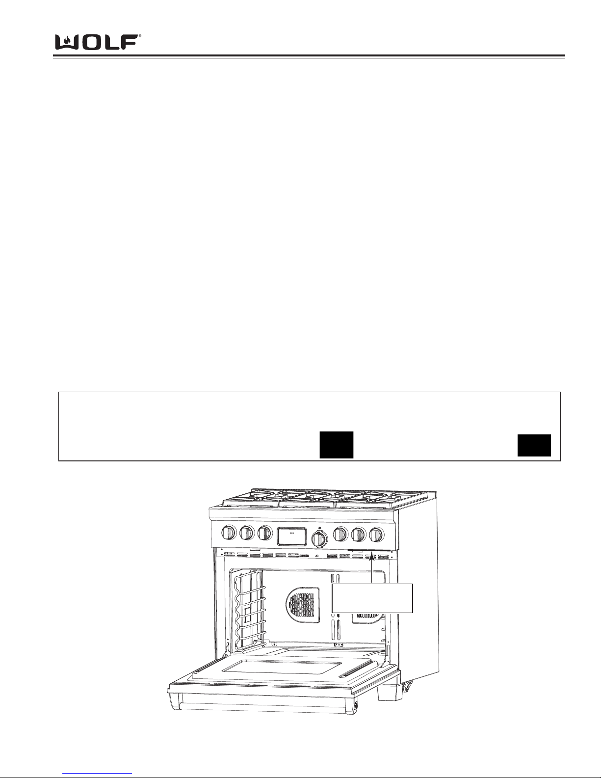
• See Figure 1-1 for serial tag layout.
• See Figure 1-2 for serial tag location.
Wolf Appliance Company, LLC
Fitchburg, WI
Gas INPUT RATING EACH BURNER - BTU/HR
Man. Press. Left Rear Burner – Other Top Burners Griddle – Charbroiler – French Top –
ELECTRICAL RATING: Volts – Amps – Hertz -
Model # - Serial # -
BD
MINIMUM HORIZONTAL CLEARANCE FROM SIDES AND BACK OF APPLIANCE TO ADJACENT COMBUSTIBLE CONSTRUCTION EXTENDING 18” ABOVE THE COOKING SURFACE 12” FROM SIDE WALLS 0” FROM
REAR WALL MINIMUM CLEARANCE BETWEEN ADJACENT COMBUSTIBLE MATERIALS BELOW THE
COOKING SURACE AND THE BACK AND SIDE OF THE APPLIANCE: 0”. MAXIMUM DEPTH FOR OVERHEAD
CABINETS IS 13” MINIMUMBERTICAL DISTANCE BETWEEN THE COOKING SURFACE AND THE BACK AND
SIDE OF THE APPLIANCE: 30”, MINIMUM VERTICAL DISTANCE BETWEEN THE TOP BROILER GRID TO
UNPROTECTED OVERHEAD COMBUSTIBLE SURFACES 36”, MINIMUM HORIZONTAL DISTANCE BETWEEN
OVERHEAD CABINETS INSTALLED TO EITHER SIDE OF THE APPLIANCE SHALL NOT BE LESS THAN THE
NOMINAL WIDTH OF APPLIANCE TO BE USED IN CONJUNCTION WITH A SUITABLE VENT HOOD ONLY.
COOKING UTENSILS SHALL NOT BE USED ON AN OPEN TOP BROILER SECTION, MINIMUM HORIZONTAL
CLEARANCE FROM ISLAND INSTALLTION COOKTOP TO COMBUSTIBLE SIDE AND BACK WALL IS 12”
“ANSI Z21.1 “HOUSEHOLD GAS COOKING APPLIANCES”
“CSA IR 58, 1995”
Figure 1-1. Typical Serial Tag Layout
Figure 1-2. Serial Tag Located Underneath the Bottom of the Control Panel
Serial Tag Located
Underneath Bottom
of Control Panel

DDuuaall FFuueell RRaannggee
General Information
1-6
MODEL FEATURES
• Natural or LP gas rangetop with dual convection electric oven(s)
• Small 18-inch oven on 48-inch dual fuel range is single convection
• Stainless steel exterior finish
• Platinum bezel surrounds all knobs, Chrome and Bronze optional
• Option of Red or Black knobs
• Dual stacked sealed 15,000 burners with automatic re-ignition at all settings
• Dual stacked burners all have simmer capabilities
• Melt feature on one 9,200 Btu burner
• 11” or 22” 15,000 BTU (13,000 BTU - LP) Griddle with Infrared burner(s) and safety shut off system
• 11” or 22” 16,000 BTU Charbroiler with Infrared burner(s)
• 22” 15,000 BTU French Top burner with safety shutoff system
• Continuous cast iron porcelain top grates
• Pivoting touch control panel
• Coaxial temperature displaying oven knob
• Eight cooking modes
• Bake Mode
• Bake Stone Mode
(30” and 36” cavities only)
• Broil Mode
• Convection Mode
• Convection Bake Mode
• Convection Broil Mode
• Convection Roast Mode
• Roast Mode
• Proof Mode (18” only)
• Self-cleaning oven(s)
• Dehydration Feature
• Proof Feature (30” and 36” cavity)
• Delayed Start Feature
• Probe Feature
• Sabbath Feature
• Spring/damper door system
• Temperature probe
• Full extension bottom rack
• Hidden bake element
• Oven door windows and dual halogen lighting
• Blue porcelain oven interior
• Adjustable stainless steel legs in front and adjustable rear casters
• Optional Bake Stone
• High altitude conversion kit available for units installed above 8,000 feet
• Two and five year residential warranty
• CSA certified for US and Canada

General Information
1-7
DDuuaall FFuueell RRaannggee
MODEL NUMBER KEY
Refer to this key for an example of the model numbers.
Model: DF 36 6 CG-LP
Product Type
DF Dual Fuel
Size
30 30 - inch wide unit
36 36 - inch wide unit
48 48 - inch wide unit
60 60 - inch wide unit
Surface Burners
2 2 - Sealed burners
4 4 - Sealed burners
6 6 - Sealed burners
Model Features
C Charbroiler (11")
G Griddle (11")
F French Top (22")
DG Griddle (22")
DC Charbroiler (22")
Fuel
LP Propane Gas
DDuuaall FFuueell RRaannggee
General Information
1-8
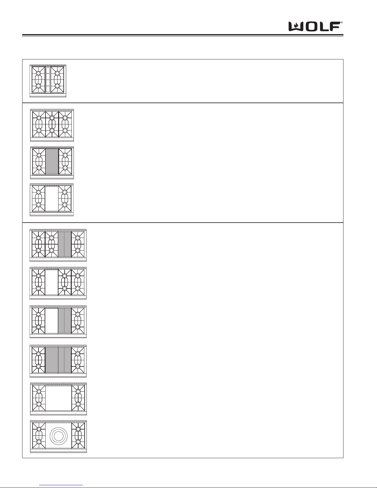
TOP CONFIGURATIONS OF 30”, 36” and 48” DUAL FUEL RANGES
DF486C 48” Dual Fuel Range with Six Burners and 11” Charbroiler
DF486G 48” Dual Fuel Range with Six Burners and 11” Griddle
DF484CG 48” Dual Fuel Range with Four Burners and 11” Charbroiler and
11” Griddle
DF484DC
48” Dual Fuel Range with Four Burners and 22” Double Charbroiler
DF484DG 48” Dual Fuel Range with Four Burners and 22” Double Griddle
DF484F 48” Dual Fuel Range with Four Burners and 22” French Top
DF304 30” Dual Fuel Range with Four Burners
DF366 36” Dual Fuel Range with Six Burners
DF364C 36” Dual Fuel Range with Four Burners and 11” Charbroiler
DF364G 36” Dual Fuel Range with Four Burners and 11” Griddle
General Information
1-9
DDuuaall FFuueell RRaannggee
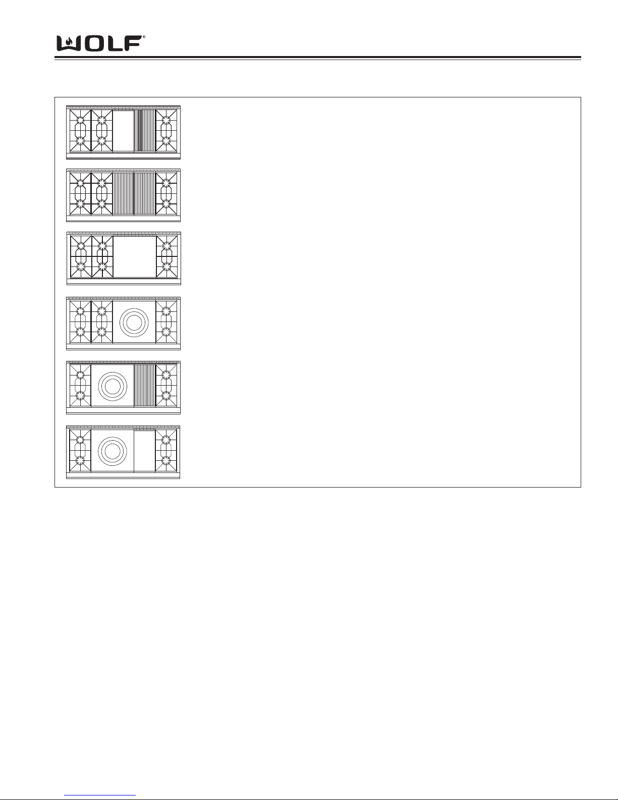
TOP CONFIGURATIONS OF 60” DUAL FUEL RANGES
DF606CG 60” Dual Fuel Range with Six Burners and 11” Charbroiler and
11” Griddle
DF606DC 60” Dual Fuel Range with Six Burners and 22” Charbroiler
DF606DG 60” Dual Fuel Range with Six Burners and 22” Griddle
DF606F 60” Dual Fuel Range with Six Burners and 22” French Top
DF604CF 60” Dual Fuel Range with Four Burners and 11” Charbroiler and
22” French Top
DF604GF 60” Dual Fuel Range with Four Burners and 22” French Top and 11”
Griddle
Note: LP units will be designated with a -LP at the end of the model number.

DDuuaall FFuueell RRaannggee
General Information
1-10

Installation Information
2-1
DDuuaall FFuueell RRaannggee
SECTION 2
INSTALLATION
INFORMATION
DDuuaall FFuueell RRaannggee
Installation Information
2-2
INSTALLATION INFORMATION
This section of the manual covers some of the installation issues that a service technician may need to know when
servicing a Wolf Dual Fuel Range. If additional installation information is needed after reviewing this section of the
manual, please refer to the Installation Guide or contact the Wolf Appliance Customer Service Department.
Electrical Requirements
Required Electrical Supply
• 240 volts AC, 60 Hertz, 30 ampere fused electrical supply for 30” and 36” units.
• 240 volts AC, 60 Hertz, 50 ampere fused electrical supply for 48” and 60” units.
• Separate circuit serving only this appliance.
• Installation site must be equipped with a properly grounded receptacle.
Maximum Connected Load
• 5,200 Watts for 30” and 36” units.
• 10,000 Watts for 48” and 60” units.
Minimum Electrical Wire Size
30” and 36”
• L1 and L2 - 12 AWG
• Neutral - 16 AWG
• Ground - 12 AWG
48” and 60”
• L1 and L2 - 8 AWG
• Neutral - 12 AWG
• Ground - 10 AWG
The unit is designed with a terminal block on the rear of the range. The terminal block allows for 3-wire or 4-wire
installation. For a 4-wire installation, the ground strap from the unit to the terminal block must be cut. Two concentric knockouts (on the terminal block), are provided to allow a certified electrical contractor to wire the range directly
to a junction box.
The terminal block will also accept an appliance power cord. The power cord must be sized correctly for the units
voltage and amperage.
Please refer to state, municipal and local codes for the best means to connect the appliance to the electrical power
supply.
A SHOCK HAZARD COULD EXIST IF THE ELECTRIC RECEPTACLE OR THE POWER CORD ARE
NOT PROPERLY GROUNDED AND POLARIZED.
The appliance may experience ignition problems if
not properly grounded and polarized.
Installation Information
2-3
DDuuaall FFuueell RRaannggee
Gas Requirements
Wolf Dual Fuel Ranges are manufactured to work with natural gas or LP gas (Liquid Propane gas). The model /
serial rating plate, located on the bottom of the control panel assembly just above the oven door on the far right, has
information on the type of gas that should be used. If this information does not agree with the type of gas available,
check with the local gas supplier.
Natural Gas Manifold Pressure
Standard natural gas orifices on the appliance are set for 5” WC (Water Column Pressure).
Liquid Propane Manifold Pressure
The standard propane gas orifices on the appliance are set for 10” WC (Water Column Pressure).
Gas Supply Line Size
• 3/4 inch rigid pipe to the range location
• For LP gas, piping or tubing size can be 1/2"
minimum.
NOTE: A smaller size pipe on long runs may result in insufficient gas supply.
A CSA design-certified, 3-foot long, 1/2" or 3/4" ID,
flexible metal appliance connector is recommended
for connecting this range to the gas supply line.
Gas Supply Pressure
• Maximum line pressure for natural gas and LP is 14” WC; 1/2 psi (3.5 kPa).
• Minimum line pressure for natural gas is 7” WC.
• Minimum line pressure for LP gas is 11” WC.
Gas Pressure Regulator
To control and maintain a uniform gas pressure in the
gas manifold, Wolf gas appliances must be connected
to the gas supply line through a pressure regulator.
The burner orifices are sized for the pressure delivered
by the regulator. Never attempt to operate a Wolf gas
appliance without the use of the proper pressure
regulator.
The maximum gas supply pressure to the regulator
should never exceed 14” WC (Water Column
Pressure); 1/2 psi (3.5kPa)
Do not kink or damage the connector when moving
the range
DDuuaall FFuueell RRaannggee
Installation Information
2-4
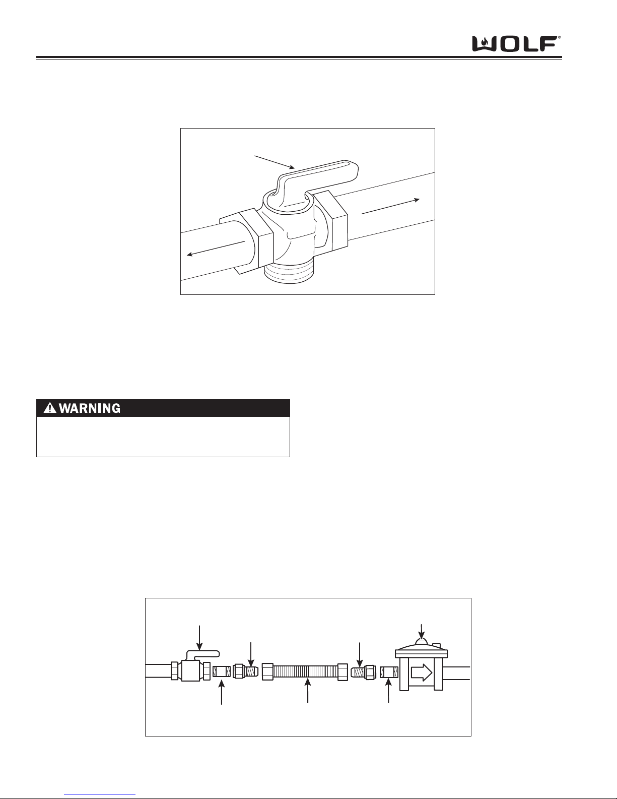
Gas Shut-off Valve
The supply line must be equipped with an approved shut-off valve. This valve should be located in accordance to all
national, local codes and ordinances. (See Figure 3-1).
Leak Testing
Use a brush and liquid detergent to test all gas connections for leaks. Bubbles around connections will indicate a
leak. If a leak appears, shut off gas valve controls and adjust connections. Then check connections again. Clean all
the detergent solution from the range.
An electronic leak detector can also be utilized to test for leaks.
Supply Line Connection
All connections must be wrench-tightened. Do not make connections to gas piping too tight. Making the connection
too tight may crack regulator and cause a gas leak. Do not allow pipes to turn when tightening fittings, tubing in the
burner box may also bend and begin to leak.
Assemble flexible metal connector from gas supply pipe to pressure regulator. Determine fittings required, depending on size of gas supply line, flexible metal connector and shut-off valve. (See Figure 3-2).
Use a pipe-joint compound made for use with natural and LP gas. If flexible metal connector is used, be
sure tubing is not kinked.
NEVER USE OPEN FLAMES TO CHECK FOR GAS
LEAKS. DO NOT USE LIQUID NEAR VALVE
STEMS.
Shut-off Valve
(open position)
To Cooktop
Gas Supply Line
Fig. 3-1. Shut-off Valve
Manual
Shut-off Valve
1/2" Adapter
1/2" Adapter
Pressure
Regulator
1/2" Nipple
(use pipe-joint compound)
1/2" Nipple
(use pipe-joint compound)
Flexible Metal Connector
Fig. 3-2. Gas Connection
Installation Information
2-5
DDuuaall FFuueell RRaannggee
E
LOCATION OF
ELECTRICAL
36"
(91.4)
367/8"
(93.7) TO
COOKING
SURFAC
E
30" min (76.2)
COOKING SURFACE
TO COMBUSTIBLE
CONSTRUCTION
44" min (91.4)
TO CHARBR
OILER
30" min (76.2)
TO BOTTOM OF
VENTILA
TION HOOD
VENTILATION HOOD
COMBUSTIBLE CONSTR
UCTION
18" min (45.7)
TO COOKING
SURFACE
13" max
(33.0)
LOCATION OF GAS AND
ELECTRICAL EXTENDS 3"
ON FLOOR FROM BACK WALL
ISLAND INSTALLATIONS: 12" MINIMUM
CLEARANCE FROM BACK OF RANGE
TO COMBUSTIBLE CONSTR
UCTION
B
FINISHED ROUGH OPENING WIDTH
COOKING SURFAC
E
C
31/4"
(8.3)
D
LOCATION
OF GAS
SUPPL
Y
6" min
(15.2)
TO WALL
357/8"
(91.1)
367/8" (93.7)
TO COOKING
SURFACE
367/8"
(93.7)
OVERALL
HEIGHT
A
O
VERALL WIDTH
25"
(63.5)
241/4"
(61.6)
271/2"
(69.9)
291/2" (74.9)
OVERALL DEPTH
LEGS AND CASTERS ALLOW
21/8"
HEIGHT ADJUSTMENT
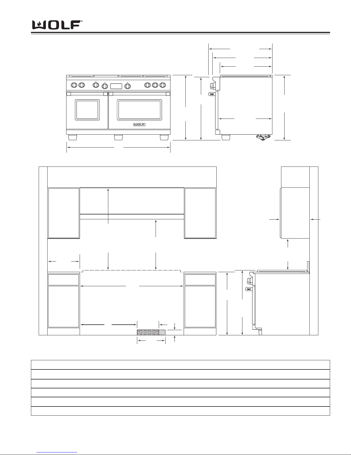
Installation Dimensions
I
nstallation Dimensions 30" Range 36" Range 48" Range 60" Range
A *Overall width of range 29 7/8" 35 7/8" 47 7/8" 60 1/8"
B Finished rough opening width 30" 36" 48" 60 1/4"
C Dimension from edge of rough opening 8 1/2" 8 1/2" 24" 31"
D Location of gas supply 10" 15" 10" 10"
E Location of electrical 13" 19" 13" 13"
*width may vary to +1/8"
Figure 3-3. Dimension Chart
DDuuaall FFuueell RRaannggee
Installation Information
2-6
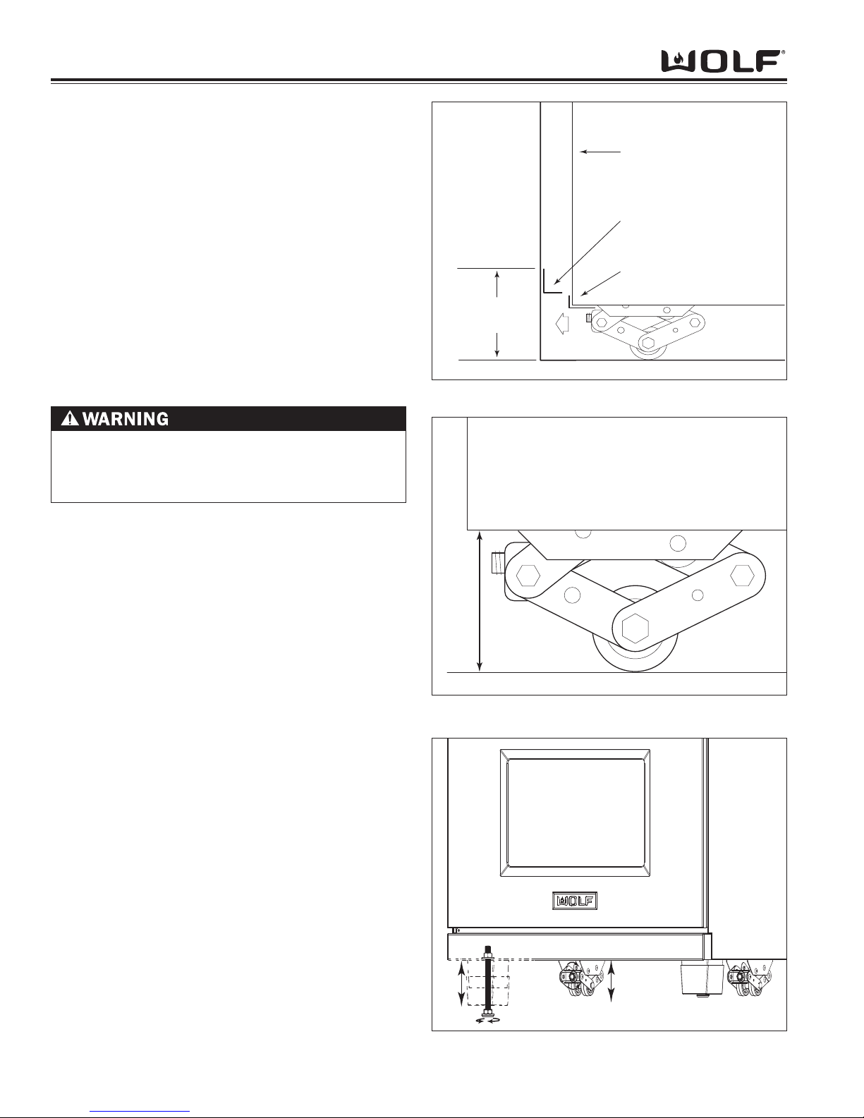
Anti-Tip Bracket Installation
Raise the unit to desired height using the rear leveling
casters and adjusting the front adjustable legs.
Try fitting the unit in place to verify the correct height.
Measure from the floor to the top of the range base
flange on the back of the unit. Add 1/8" to this dimension, mark this height on the wall behind the unit. This
will be the location of the bottom edge of the anti-tip
bracket. Try to center the mark between the cabinets.
For 48-inch and 60-inch ranges, care must be taken to
verify that the anti-tip bracket does not interfere with the
inner cavity supports. Locate a stud or other solid
mounting source, install the anti-tip bracket at the same
level as this line. Push the unit back, ensure the rear
base flange fits under the anti-tip bracket. (See Figure
3-3).
Unit Leveling
Rear Caster Adjustment
The Dual Fuel range has rolling casters, which allows
easy movement of the range by picking up on the front
of the unit. The range comes from the factory at an
overall height of 35-7/8" (from floor to the top of the
bullnose) before any height adjustment. The casters
allow for 2-1/8" height adjustment.
NOTE: Do not lift by oven door(s) handle.
To raise or lower rear caster, reach directly underneath
unit to rear caster and attach a 3/4” socket with an long
extension onto the adjusting bolt located on front of
caster assembly. Now, attach a drill or socket wrench
to extension and turn bolt left or right to raise or lower.
(See Figure 3-6)
Front Leveling Leg Adjustment
Dual Fuel ranges can be leveled at the front by turning
the front leveling legs as indicated in figure 3-6 The
legs allow for 2-1/8" height adjustment.
To raise or lower front leveling legs, use an adjustable
wrench to turn the leveling leg nut to the left or right to
raise or lower. (See Figure 3-6).
The stainless steel cover over the leveling leg floats up
or down to conceal the leveling leg from view. If leveling leg is still visible and the stainless steel cover is all
the way down, replace the stainless steel cover with a
longer version, available as a sales accessory.
ANTI-TIP BRACKET MUST BE ANCHORED TO
WALL BEHIND UNIT SO IT IS DIRECTLY ABOVE
THE BASE FLANGE OR APPLIANCE MAY TIP FORWARD
SIDE PANEL
ANTI-TIP
BRACKET
BASE FLANGE
WALL
FLOOR
TO FLOOR
5 3/4" min.
Figure 3-4. Anti-Tip Installation
CASTERS ALLOW
2 1/8" HEIGHT ADJUSTMENT
FLOOR
Figure 3-5. Caster Height
Figure 3-6. Caster and Leveling Leg Adjustment

Operation Information
3-1
DDuuaall FFuueell RRaannggee
SECTION 3
OPERATION
INFORMATION

DDuuaall FFuueell RRaannggee
Operation Information
3-2
THEORY OF OPERATION
A service technician should understand how a gas appliance operates before attempting to service the appliance.
This section provides descriptions of the different types of fuel gases and explains gas heating values. A definition
of specific gravity of gas is given along with its characteristics and effects. Gas combustion principals are explained
and gas burner components are described and illustrated. The end of this section contains illustrations which
demonstrate basic cooking appliance theory of operation.
Types of Fuel Gas:
Gases used to supply heat energy are called fuel gases. Common fuel gases are not simply one kind of hydrocarbon, they are mixtures of hydrocarbon gases. They contain other gases as well, such as free hydrogen, carbon
dioxide and nitrogen. As an example natural gas might contain 85% methane, 12% ethane and 3% of other gases.
The presence of each of these gases in the fuel gas has some effect on the nature of the gas.
Some common fuel gasses are methane [CH
4], ethane [C2H6], Propane [C3H8] and butane [C4H10]. Propane and
butane are nearly odorless. Natural gas that is processed to remove condensables and moisture, has little or no
odor and no color. Odorants are added to natural gas before distribution to aid in leak detection. A common odorant
used is a colorless liquid containing sulfur compounds.
Heating Value of Gas:
Heat energy produced when burning a fuel gas is commonly expressed in British Thermal Units (BTU). One BTU of
heat will raise the temperature of one pound of water one degree Fahrenheit.
The more carbon and hydrogen atoms in each molecule of a fuel gas, the higher its heating value. Natural gas
which is high in methane has a heating value of about 950 to 1150 BTU per cubic foot. The variance is due to the
various other substances found in natural gases. The more ethane, propane or butane in the gas raises the heating
value. Propane, or LP gas, has a heating value of about 2500 BTU per cubic foot, and butane about 3200 BTU per
cubic foot.
Specific Gravity of Gas:
The specific gravity of a gas is the weight of one cubic foot, or the gas compared to one cubic foot of dry air. When
stating the specific gravity of a gas, a pressure and temperature must be clearly stated. In the gas industry, the
standard conditions of pressure and temperature are 30.0 inches of mercury and 60° F. A pressure of 30.0 inches of
mercury will sustain a column of mercury 30 inches high in a tube with a vacuum on top of the column. Since air is
used as the reference, its specific gravity is always 1.0. This value of 1.0 has no direct physical meaning with
regard to air, such as its density. It is only a relative number or ratio used to express specific gravity of other gases.
The specific gravity of a gas will determine if the gas will rise or fall when released into the air. Natural gas will rise
since its specific gravity is less than 1.0 at 0.4 to 0.8. Propane has a specific gravity of 1.5 and butane 2.0. These
gases will fall when released into the air. They sometimes collect in low spots into pools which become a hazard if
open flames are present.
In addition, specific gravity has two other characteristics. It has an important effect on the flow of gases through orifices, and hence the rating of the burners. Gas flow through an orifice is dependent upon the orifice size and the
gas pressure upstream of the orifice. More of a lighter gas will flow through a given orifice size than a heavier gas
at the same gas pressure. This effect is taken into account in tables and calculators used to select orifice sizes for
burners.
The gas flow in pipes is also affected by specific gravity. At a given pressure at a pipe inlet, more lighter gas will
flow through a pipe than a heavier gas.
Principals of Gas Combustion:
Combustion
When oxygen acts with a substance to produce large amounts of heat rapidly.

Operational Information
3-3
DDuuaall FFuueell RRaannggee
Requirements for Combustion
There are three required elements for combustion to occur; Fuel (Gas), Oxygen (Air) and Heat (Ignition
Temperature, which for gas is between 1100°F/593°C and 1200°F/649°C). All must be present. Removing any one
of the three and combustion will cease.
Chemistry of Combustion
Combustion of gas is a chemical reaction between fuel gas and oxygen. The basic elements of common fuel
gasses are hydrogen [H] and carbon [C]. When hydrogen burns, water vapor [H
2O] is produced. Complete burning
of carbon in fuel gases form carbon dioxide [CO2] and water vapor [H2
O].
Controlled Combustion
Controlled combustion takes place when gas and air are supplied at proper rates to assure complete combustion of
the gas in a steady flame. When a gas appliance is operating properly, burning starts at the burner ports. Gas flow
is controlled by gas orifice size and gas pressure upstream of the orifice. Air is mixed with the gas before it passes
through the burner ports. This added air is called “Primary Air”. The remaining air required for complete combustion
is supplied to the burner at the point of combustion and is called “Secondary air”.
Adjustments of the gas-to-air ratio and the secondary air supply is the key to obtaining stable blue flames at a burner. Proper amounts of primary and secondary air are required for quiet and efficient burner operation and for complete combustion of the gas. Air Shutters or other devices provide control of primary air. Inlet opening and flue outlets control Secondary Air flow.
Total air
In an ideal situation, primary and secondary air is all that is needed (for the oxygen required) to burn the gas, but
some additional air is required to assure complete burning of the gas. The total air, “primary”, “secondary” and
“excess” are expressed as percentages of the amount needed. About ten cubic feet of air is required to completely
burn one cubic foot of gas. For this reason an appliance should not be operated in an air tight home.
Limits of Flammability
Not all air-to-gas mixtures will burn. Mixtures with 0% - 4% natural gas in air are too lean to burn. Mixtures of 4% 14% natural gas in air can burn with a controlled flame. Flammability limits come into play when primary air adjustments are made on burners. If too much primary air is used, the mixture may become too lean and fall below flammability limits, thus preventing combustion.
Incomplete Combustion (Causes and Effects)
To obtain complete combustion, sufficient amounts of air must be supplied to the process. This air must have a reasonably normal oxygen content. Complete burning of gas produces harmless carbon dioxide gas and water vapor.
If the air supply is insufficient, incomplete combustion occurs resulting in the formation of toxic by-products, such as
carbon monoxide [CO] or aldehydes.
Carbon monoxide is colorless and odorless. Inhaling carbon monoxide in sufficient quantities could cause death by
reducing oxygen levels in the blood.
Aldehydes, which are equally dangerous, have a sharp and penetrating odor which is easily detected by smell at
very low concentrations. The odor caused by aldehydes should not be confused with odorants added to natural gas.
The absence of aldehydes does not assure that carbon monoxide is not present. However, if the odor of aldehydes
is present, then carbon monoxide is virtually always present.
Gas Burner Operation
A gas burner is a device to burn gas under control in order to produce useful heat. Primary air is brought into the
burner from outside of the appliance at atmospheric pressure. The gas jet streaming from the orifice draws primary
air with it into the burner.
The gas/air mixture, combined with a spark at the burner port(s) and the secondary air creates a controlled burn.
DDuuaall FFuueell RRaannggee
Operation Information
3-4
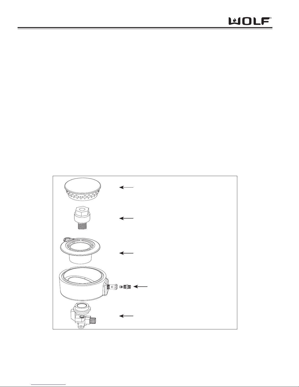
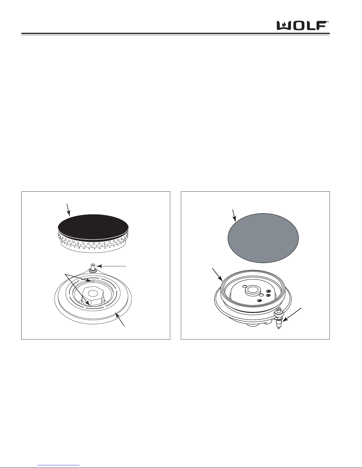
Burner Components: (PTS 17000000)
Burner Head - The component containing the burner ports where the gas/air mixture ignites. The burner ports are
distributed in a useful pattern to optimize heat transfer. The flames should be spread so they can be easily reached
by secondary air and provide a stable blue flame.
Venturi - Threaded brass pipe that threads into the jet holder through the distribution rings which narrows and then
flares out again. This pipe helps maintain proper and constant primary air injection.
Inner Distribution Ring - Routes the gas from the simmer orifice hood to the simmer port holes located on the
burner cap.
Outer distribution Ring - Routes the gas from the main burner orifice hood to the main burner port holes on the top
of the burner head.
Jet Holder - This component is mounted to the burner mounting bracket and to the burner box. The main burner
orifice is threaded into the jet holder as well as the venturi. It is the main support for the burner components.
Gas Orifice - An opening or hole which regulates or limits the amount of gas flowing to a burner. Gas flow rate (volume) depends on the size of the orifice (hole) and the gas pressure at the inlet of the orifice.
Burner Head
Venturi
Inner Distribution Ring
Outer Distribution Ring
Jet Holder
with Connector and Orifice
with Orifice
Figure 3-1. Burner Components
Operational Information
3-5
DDuuaall FFuueell RRaannggee
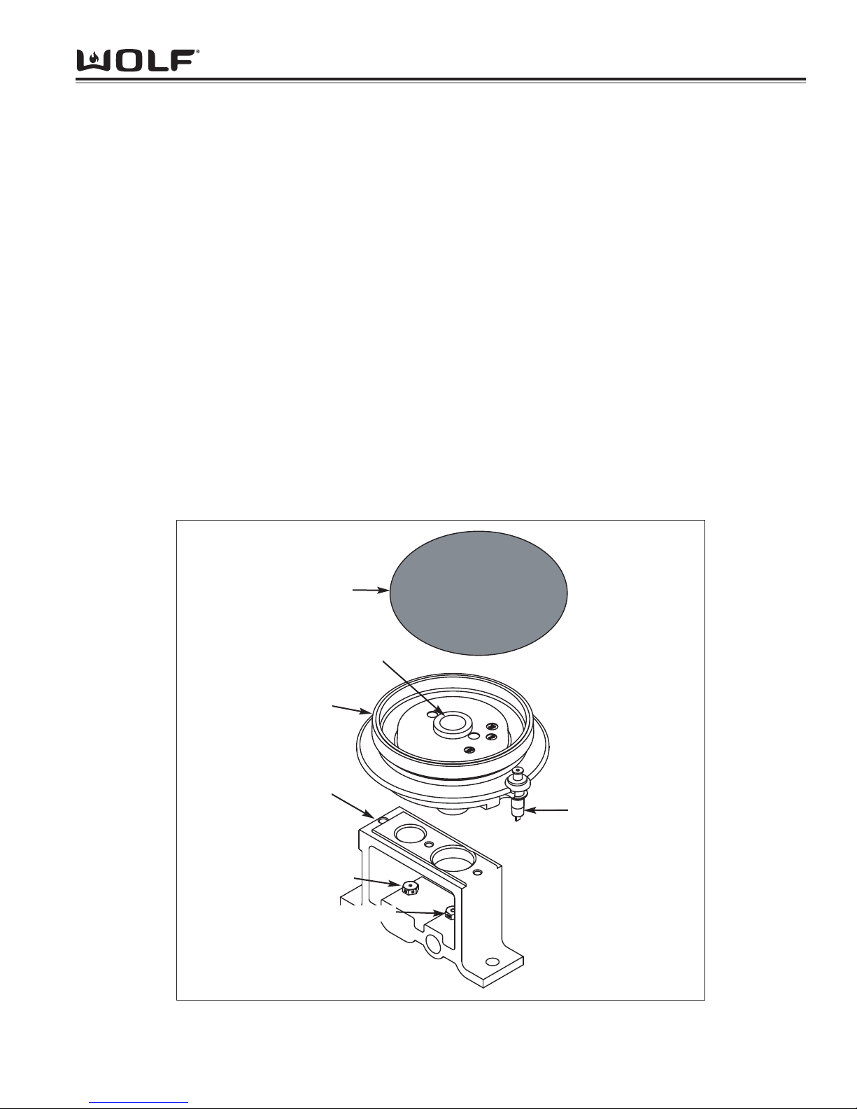
Figure 3-1A. Burner Components
Electrode
Burner
Burner Cap
Orifice Holder
Simmer Orifice
Main Orifice
Venturi
Burner Components: SWS 17000000
Burner Cap - Provides the upper portion of the ports required to create a combustible mix and proper flame quality
of the burner and the decorative top for the burner with a black porcelain coating.
Burner - Contains the burner ports where the gas/air mixture ignites. The burner ports are distributed in a useful
pattern to optimize heat transfer. The flames should be spread so they can be easily reached by secondary air and
provide a stable blue flame. The burner also incoorporates the Inner Distribution Ring, which Routes the gas from
the simmer orifice to the simmer port holes, and the Outer Distribution Ring, which routes the gas from the main
burner orifice to the main burner port holes.
Venturi - Helps maintain proper and constant primary air injection.
Electrode - The Electrode supplies the spark to ignite the burner. The electrode senses the flame, once the burner
is ignited and will stop sparking. If no flame is sensed, and the valve is opened, the electrode will start sparking to
re-ignite the flame. This is part of the auto-reignition system.
Orifice Holder - This component is mounted to the burner mounting bracket and to the burner box. The Simmer
and Main orifice is threaded into the orifice holder and routes the gas to the appropriate ports of the burner. It is the
main support for the burner components.
Simmer Orifice and Main Orifice - An opening or hole which regulates or limits the amount of gas flowing to a
burner. Gas flow rate (volume) depends on the size of the orifice (hole) and the gas pressure at the inlet of the orifice.
DDuuaall FFuueell RRaannggee
Operation Information
3-6
Types of Burners:
Blue Flame Burners
All Wolf open surface burners, including the French Top burners are blue flame burners. With this type of burner,
primary air is mixed with the fuel gas before the gas reaches the burner ports. An orifice is used to regulate gas
flow to the burner and is sized to draw exact amount of air into the burner body. Air, which is mixed with the gas
inside the burner body then exits the burner ports located in the burner head, where it is ignited. Secondary air is air
from around the flames. The flame produced has several zones, each represents a stage in burning of the gas.
The burner tip has a thin dark blue cone called the inner or primary cone. A lighter cone called the outer cone, surrounds the inner cone. Air around the flame diffuses into the flame to burn at the outer cone. If conditions are perfect, products from the inner cone burn here. The final products of burning are carbon dioxide and water vapor. An
outer mantle surrounds the outer cone where burning is usually completed. It is nearly invisible and glows only
because of the high temperature of the final combustion.
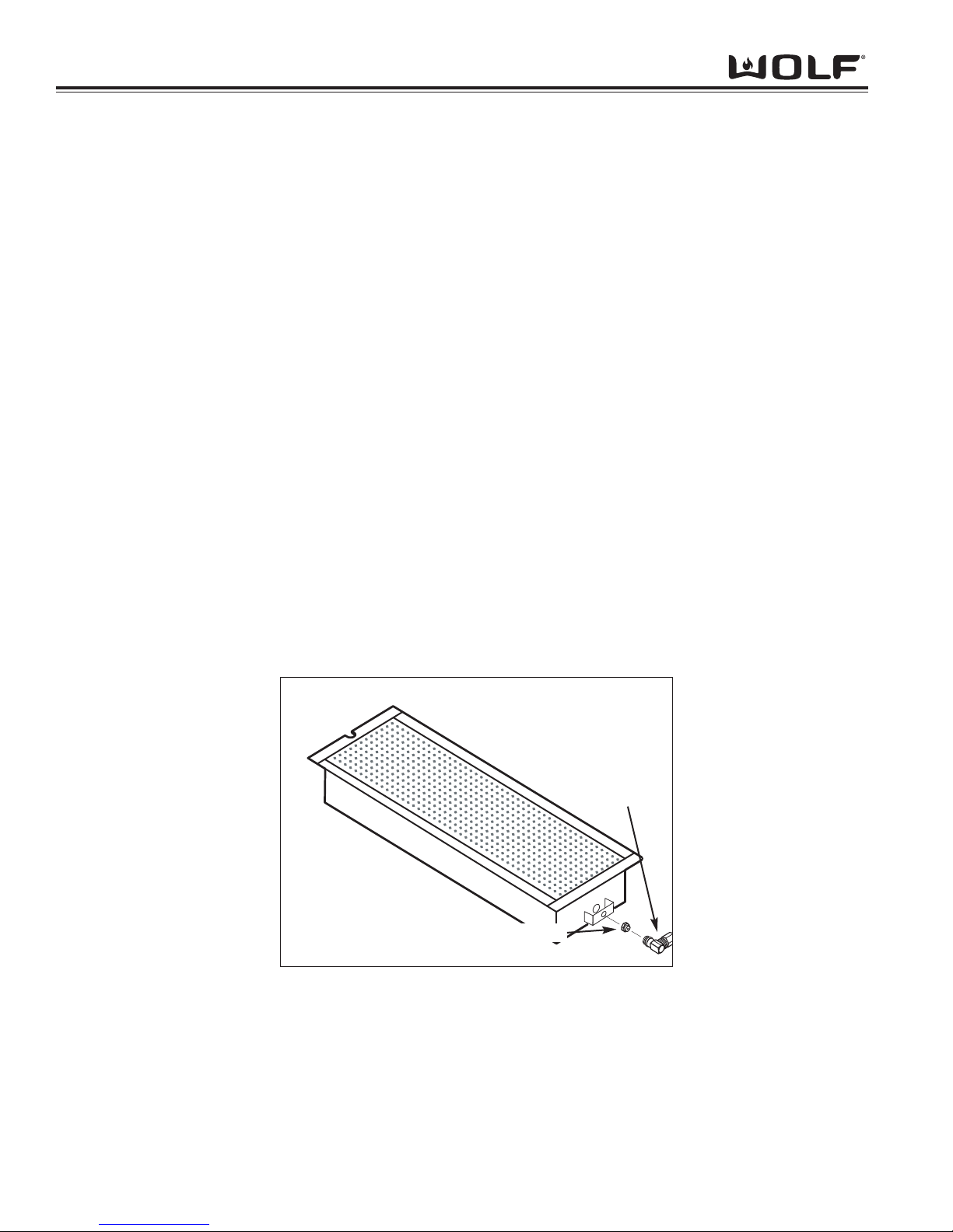
Infrared Burners
Wolf dual fuel ranges also use infrared burners. The under-fired application for the charbroiler and the griddle uses
a porous refractory ceramic tile burner. (See Figure 3-2) With this type of burner, a substantial amount of energy
output is in the form of infrared radiant energy. With infrared heat, thermal energy is transmitted through space without heating the medium through which it travels. Infrared energy is usually not affected by air flowing between the
burners and heated surfaces because of the burner’s numerous and tiny flames. This type of heat is very efficient
and compact. The under-fired refractory infrared burner requires 100 percent primary air and is designed to have a
hot glowing burner surface. The flame burns close to the burner surface at a high temperature.
NOTE: There is no shutter on infrared burners for adjusting the primary air and there is no change in orifice size for
different altitude.
Figure 3-2. Infrared Burner
CHARBROILER AND GRIDDLE ORIFICE
GAS ORIFICE
ELBOW

Operational Information
3-7
DDuuaall FFuueell RRaannggee
OPERATION OF THE DUAL FUEL RANGE
Surface Burners
A spark electrode ignites each surface burner. This control eliminates the need for continuous open flame pilots.
For added safety and convenience, each burner is designed with an electronic re-ignition system. This feature
enables any burner to automatically re-light in the event it is accidentally extinguished.
This unique dual stacked burner design combines all the burner parts in one configuration. Large burners provide a
Btu/hr rating of 15,000 on HIGH and a High Simmer Btu/hr rating of approximately 3300. Small burners provide a
Btu/hr rating of 9,200 on HIGH and a High Simmer Btu/hr rating of approximately 1600. All burners have simmer
settings.
A distinguishing feature of the Wolf low Btu/hr control is its constant, low heat output without continuous ignitions.
Flame diameter remains full size, only the heat output is lowered. This is the ultimate control for simmering food.
After removing burner parts for any reason, it is extremely important that the burners are re-assembled correctly.
The burner cap has a special orientation and should be seated flatly (see Figure 3-3 and Figure 3-3A).
Rotate burner cap until you feel it drop and click into position.
This patented dual stacked burner configuration makes it possible to enjoy cooking at full flame as well as maintaining control while simmering at the lowest flame setting.
Grate Placement
Low profile cast iron grates are designed for a close fit. This enables pans to move easily from one burner to another without having to lift the pan or have it tip over between the grates. Each grate sets securely on dimples on each
corner of the cooktop pan. Continuous grates are interchangeable.
Control Knobs
The control knobs are positioned to correspond to the burners they regulate. The knobs on the far left regulate the
burners on the left side. Conversely, the knobs on the far right regulate the burners on the right side.
Burner Lighting
To light a burner push in and turn the corresponding control knob counter clockwise to the HIGH setting. You will
hear “clicking” and see the burner ignite. Once the burner is lit, continue turning the knob counter clockwise to any
one of the settings, HIGH through LOW.
To select a simmer setting, turn the knob to the LOW setting. You will feel a stop-detent in the knob rotation. Push
in on the knob, continuing to turn it counter clockwise. This moves the flame to the second tier. Now, select any
variation within the SIMMER flame settings, HIGH through LOW.
Each knob is designed to be a “push-to-turn knob”. Although this is a child-safe design, children should never be left
unattended in the kitchen when the range is in use.
Power Outage
In case of a power outage, the surface burners can be re-lit manually. Turn the control knob to “high” and place a
flame near the igniter to light the burner.
DSI board operation (Griddle & French Top units only)
The DSI board serves the purpose of igniting the griddle burner, detecting the presence of this flame, and provides
the signal to open the gas valve. When the thermostat is turned on, the red (call for heat) light comes on and the
gas solenoid is opened. At this time you will hear a series of sparks and it will begin to check for the presence of a
flame. If the igniter probe does not detect flame within a short period of time, the gas valve solenoid shuts off and
there will be a delay before trying to reignite (this allows time for the non-combusted gas to dissipate). This process
will reoccur in three sets and if it fails a third time the DSI board will shut down and will wait for the thermostat to be
turned off and on before attempting to reignite. If flame detection is lost during operation this board will also allow
time for the non-combusted gas to dissipate, but will attempt to reignite after this delay.
DDuuaall FFuueell RRaannggee
Operation Information
3-8
Burner Cap
Igniter
Sealed Burner
Alignment
Tabs
Figure 3-3. Stacked Dual Burner Assembly (PTS 17000000)
Charbroiler
This optional feature is designed with an infrared burner to give the highest quality and most efficient method of gas
grilling. These burners become an orange-red color at the surface of the ceramic tiles. When the tiles are glowing,
they transfer an intense heat to the food being grilled. This chars the outside of the food and leaves the inside tender and juicy.
The infrared burner is designed to operate at a full heat output of 16,000 BTU/hr. It is recommended using the Wolf
blank-off plate when grilling most foods.
Charbroiler Operation
• Turn on the ventilation hood prior to using the charbroiler.
• If the knob is not set fully at "HIGH", the burner may turn blue and the automatic igniter will begin sparking.
Turn the knob back to "HIGH".
• Preheat grill for about ten minutes before adding the food. The tiles will have an orange glow.
• For the 22-inch charbroiler, there are two separate burners with separate control knobs, which act
independently of each other.
Burner Cap
Igniter
Sealed Burner
Figure 3-3A Stacked Dual Burner Assembly (SWS 17000000)
Operational Information
3-9
DDuuaall FFuueell RRaannggee
Burner Pan
Although resistant to most
stains, it is not totally impervious to damage. Salt and
some cooking liquids may pit
and stain surface. Always
remove these spills immediately.
Avoid using abrasive cleaners;
they will permanently scratch
the surface.
Burner Cap
Burner Grates
Control Knobs
Spark Igniters
Part Identification Material Care Recommendation
Exterior Finish
Porcelain Steel
Porcelain Enamel
(matte finish)
Never wipe a warm or hot
porcelain surface with a damp
sponge; it may cause chipping
or crazing (tiny hair-like cracks)
Porcelain-Coated Cast Iron
Metal
Ceramic
General care: Use a clean cloth or sponge, wipe
with warm water and mild detergent. Rinse and
dry immediately. Apply protective polish, always in
the same direction.
Spray degreaser: Removes fingerprints and
greasy spatters. Spray on a cloth and wipe surface. Buff dry immediately to avoid streaking.
Protective polish: Apply to surface to maintain luster and protect from some food stains
Hard water stains: Use white vinegar and water.
Cool first. Wash in warm water with liquid detergent or mild abrasive cleaners.
Foods high in acid or sugar content, such as milk,
tomatoes, sauerkraut, fruit juices and pie filling,
may pit or craze the surface. Remove as soon as
possible. Do not cook the spill on again.
Remove from cooktop and place on a flat surface
near the sink.
Non-abrasive cleaners: Hot water and liquid detergent, paste of baking soda and water, plastic pad
or sponge.
Mild abrasive and abrasive cleaners: Use sparingly.
General care: Wipe each knob with a damp cloth
and mild soap and water; rinse and dry. Never
soak or use abrasive cleaners; they will scratch the
finish and remove the markings.
Keep dry. Never spray water or cleaner directly on
the igniter. When cleaning around the surface
burner, be careful that the cloth does not catch on
the igniter and damage it.
Cleaning and Maintenance
DDuuaall FFuueell RRaannggee
Operation Information
3-10
Blank-Off Plate
(If Applicable)
Charbroiler Frame
Grate
Igniter
Mesh Screen
(If Applicable)
Part Identification Material Care Recommendation
Stainless Steel
Stainless Steel
Porcelain Coated
Cast Iron
Ceramic
Stainless Steel Wire
Wash with hot water and detergent. Use a soapfilled scouring pad to remove as much cooked-on
soil as possible. The plate will turn a metallic blue
color due to high heat; this is a permanent
change.
Remove from the range. Soak in hot water and
dish detergent. Wash thoroughly, scrubbing with
scouring pad, if needed. Rinse and dry.
When cool, lift off and set in the sink. Pour very
hot water over the cooked-on residue. Cover with
wet dish towels and pour more hot water over it.
Allow the hot, moist conditions time to help loosen
the residue. Remove remaining soil with a soapfilled scouring pad. Rinse and dry.
Avoid contact with the igniter; it is fragile and can
chip or break.
Use a wire brush to loosen any charred food particles.
Charbroiler Cleaning and Maintenance
Griddle
The cast iron griddle plate operates at 18,000 Btu/hr. It is thermostatically, controlled which means once the set
temperature is reached, the heat cycles to hold that setting. Prior to use it is necessary to "season" the griddle to
protect the surface from moisture. This process will change the appearance.
NOTE: Seasoning does not create a non-stick surface. The use of additional oil is necessary during cooking.
Griddle Operation
• To heat the griddle, push in the knob and turn counter clockwise to desired temperature. It is normal to hear a
clicking sound. This is the electronic ignition lighting the burner. When the burner is lighted, the thermostat will
control the temperature.
• Preheat for approximately 10 to 15 minutes. When the griddle is preheated, the griddle indicator light will go
out. The light will cycle on and off as the thermostat needs more heat to maintain the set temperature. This will
allow heat to be evenly distributed and reach the set temperature.
• For the 22-inch griddle, there are two separate burners with separate control knobs, which act independently of
each other.
• To turn off the griddle, turn the knob clockwise to the "OFF" position.
Griddle Care
• Use a metal spatula and scrape grease into the grease collection tray.
• When the surface has cooled, wipe it with a paper towel to remove excess grease or oil.
• Clean grease collection tray after each use. Do not allow grease to accumulate in the tray and become a fire
hazard.
• To remove the drip tray, gently pull the tray towards yourself to lift it out. Clean drip tray with soapy water and a
clean cloth.
Operational Information
3-11
DDuuaall FFuueell RRaannggee
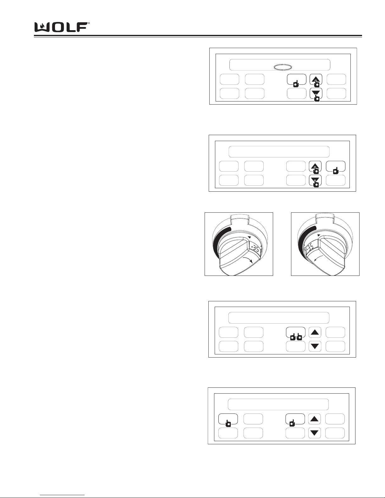
Time of Day Clock
The clock can be visible on the display during all modes. To
set clock, press the CLOCK key on display panel, “CLOCK”
will flash on and off. Next, press the up or down arrow key to
increase or decrease the time. Stop when correct time of day
shows in display window. (See Figure 3-4). Now, press the
CLOCK key or ENTER key to set clock. Two beeps will be
heard when time has been entered.
NOTE: By holding down desired arrow key, counter will rapidly toggle through the numbers.
NOTE: Time will change from am to pm by passing the 12:00
mark.
Oven Timer
The oven has a timer that operates independently from the
oven controls. Once a time is set in hours and minutes, the
countdown is seen in the display window. Only the last
minute counts down in seconds. To initiate oven timer, press
TIMER key. (See Figure 3-5). Next, press the arrow up or
arrow down key to increase or decrease desired amount of
cooking time in hours and minutes. (See Figure 3-5). Then,
press ENTER key or TIMER key to start timer. Two beeps will
be heard. The oven will chime, time will continually flash
when timing is complete. To exit oven timer function, press
TIMER key, then press CLEAR key twice to clear time and
return to clock.
FIELD OPTION MODE
Three Field option modes allows for the user to adjust or
change specific option’s of the ECH and oven controller, such
as User Preference Offset, 12 hour to 24 hour clock and
Fahrenheit to Celsius temperature.
UPO (User Preference Offset)
This option allows the user to offset a specific oven temperature ±35° in 1°F (Fahrenheit) increments. To initiate, press
and hold the CLOCK key for 5 seconds. The current UPO will
be displayed in the temperature readout knob, turning the
knob at this point you can change the UPO. Turn the knob to
the left or right to increase or decrease the UPO in 1° increments as much as ±35°. (See Figure 3-6 and 3-7).
Changing Clock to 24 Hours
To set 24 hour clock, press and hold CLOCK key on display
panel for 5 seconds. (See Figure 3-8). Now, press CLOCK
key to change from 24 hour to 12 hour or vice versa. (See
Figure 3-8). Then, press the ENTER or after short delay the
clock will set by default.
Fahrenheit to Celsius
The oven can be changed from Fahrenheit to Celsius temperature or visa versa. To initiate, press and hold the CLOCK
key on display panel for 5 seconds. Now, press the COOKTIME key to change from °F and °C or visa versa. (See
Figure 3-9). Next, press the ENTER key on the display panel
or after short delay °F or °C will set by default.
COOK
TIME
PROBE
CLOCK
ENTER
TIMER
CLEAR
STOP
TIME
OVEN
LIGHT
1:00
CLOCK
P
1
2
2
2
2
Figure 3-4. First, Press and Hold CLOCK Key for 5
Seconds. Then, Press Arrow Up or Arrow Down Key to
Set Time
COOK
TIME
PROBE
CLOCK
ENTER
TIMER
CLEAR
STOP
TIME
OVEN
LIGHT
12hr
°F
1
2
2
Figure 3-8. First, Press and Hold CLOCK Key for 5
Seconds. Then, Press CLOCK Key to toggle between 12hr
and 24hr
COOK
TIME
PROBE
CLOCK
ENTER
TIMER
CLEAR
STOP
TIME
OVEN
LIGHT
0:00
1
2
2
2
2
Figure 3-5. First, Press TIMER Key. Then, Use Arrow Up
or Arrow Down Key to Set Desired Amount of Time
COOK
TIME
PROBE
CLOCK
ENTER
TIMER
CLEAR
STOP
TIME
OVEN
LIGHT
12hr
1
°C
2
2
Figure 3-9. First, Press and Hold CLOCK Key for 5
Seconds. Then, Press COOK TIME Key to Toggle
between °F and °C
O
F
F
B
A
K
E
B
R
O
I
L
B
A
K
E
B
R
O
I
L
R
O
A
S
R
O
A
S
T
HI
LO
Figure 3-6. Turn Knob to
Right to increase temper-
ature
O
F
F
B
A
K
E
B
R
O
I
L
B
A
K
E
B
R
O
I
L
R
O
A
S
R
O
A
S
T
HI
LO
Figure 3-7. Turn Knob to
Left to decrease tempera-
ture

DDuuaall FFuueell RRaannggee
Operation Information
3-12
COOKING MODES
The dual fuel oven has multiple cooking modes, each dedicated to give the best results for a specific kind of cooking. The
dual fuel oven also has some unique cooking features.
Most oven modes have a temperature setting of 170°F (75°C)
to 550°F (290°C). The exception is Broil, Convection Broil
and Proof mode.
NOTE: Bake Stone Element must be removed during all
cooking modes excepts Bake Stone Mode.
Bake Mode
Both the hidden bake element and broil element are used to
heat the air and cycle to maintain temperature. This mode is
best for single rack cooking, primarily bakery foods.
To initiate the Bake Mode, turn oven control knob bezel counter clockwise to BAKE. (See Figure 3-10). Temperature is
preset to 350°F (175°C). To change oven temperature, immediately turn temperature readout knob to the right to increase
oven temperature or to the left to decrease. (See Figure 3-11
and 3-12). Oven will turn on after 2 seconds or press ENTER
key. To exit Bake Mode, turn oven knob bezel to OFF.
NOTE: Always preheat for Bake mode.
NOTE: Temperature probe may be used in this mode.
NOTE: Timer function may be used during this mode.
NOTE: The temperature display alternates between set and
actual oven temperatures during preheat.
NOTE: Temperatures below 150°F (65°C) are displayed by
the word "Lo" in the oven knob display window during preheat
NOTE: Oven will chime when oven preheat temperature has
been achieved.
Bake Stone Mode
A specially designed rack and heating element are used for
this mode to produce a hot oven environment necessary for
baking on a ceramic stone. A heating element is added
under the stone to enhance the heat from both convection
fans.
To initiate Bake Stone Mode, turn the oven control knob bezel
clockwise to STONE. (See Figure 3-14). Temperature is preset at 400°F (205°C). To change temperature, immediately
turn temperature readout knob to right to increase oven temperature or to left to decrease. (See Figure 3-15 and 3-16).
Oven will turn on after 2 seconds or press ENTER key. To
exit Bake Stone Mode, turn oven knob bezel to OFF.
NOTE: “Stone” will appear and flash on hidden display and a
beep tone will be heard 30 seconds if the bake stone element
is not inserted into receptacle.
NOTE: Always preheat 25 minutes for Bake Stone mode.
Oven will chime when oven preheat temperature has been
achieved.
NOTE: Temperature probe may be used in this mode.
NOTE: Timer function may be used during this mode.
NOTE: The temperature display alternates between set and
actual oven temperatures during preheat.
B
A
K
E
B
R
O
I
L
R
O
A
S
T
B
R
O
I
L
O
F
F
B
A
K
E
B
R
O
I
L
5
0
3
LO
HI
Figure 3-10. Turn Control
Knob Bezel Counter
Clockwise to BAKE
HI
LO
B
A
K
E
B
R
O
I
L
R
O
A
S
T
B
R
O
I
L
O
F
F
B
A
K
E
B
R
O
I
L
3
5
1
Figure 3-11. Increase
Preset Temperature, Turn
Knob to Right
B
A
K
E
B
R
O
I
L
R
O
A
S
T
B
R
O
I
L
O
F
F
B
A
K
E
B
R
O
I
L
HI
LO
3
4
9
Figure 3-12. Decrease
Preset Temperature, Turn
Knob to Left
B
A
K
E
B
R
O
I
L
R
O
A
S
T
B
R
O
I
L
O
F
F
B
A
K
E
B
R
O
I
L
o
L
LO
HI
Figure 3-13. Lo appears
in display window if tem-
perature is below 150°F
4
0
0
LO HI
S
T
O
N
E
R
O
A
S
T
B
R
O
I
L
C
L
E
A
N
C
O
N
V
R
O
B
A
K
E
Figure 3-14. Turn Control
Knob Bezel Counter
Clockwise to STONE
HI
LO
S
T
O
N
E
R
O
A
S
T
B
R
O
I
L
C
L
E
A
N
C
O
N
V
R
O
B
A
K
E
Figure 3-15. Increase
Preset Temperature, Turn
Knob to Right
HI
LO
S
T
O
N
E
R
O
A
S
T
B
R
O
I
L
C
L
E
A
N
C
O
N
V
R
O
B
A
K
E
Figure 3-15. Decrease
Preset Temperature, Turn
Knob to Left
L
o
LO HI
S
T
O
N
E
R
O
A
S
T
B
R
O
I
L
C
L
E
A
N
C
O
N
V
R
O
B
A
K
E
Figure 3-16. Lo appears
in display window if tem-
perature is below 150°F
 Loading...