

Wolf CT15I, CT36I, CT30I, CT36IU, CT30IU Service Manual

subzero.com 800.222.7820
CT Induction Cooktop
Service Manual
Installation Information 5
Installation Information
Induction Cooktop
PRE-INSTALLATION SPECIFICATIONS
This section of the manual covers some of the installation issues a service technician may need to know when servicing
a Wolf Induction Cooktop. If additional information is needed after reviewing this section of the manual, please refer to
the Installation Guide or contact the Wolf Appliance Customer Service Department.
Electrical Requirements - Induction
Nominal Voltage
Model CT15I ....................... 240 VAC / 50/60 Hz / 20 amp service
208 VAC / 60 Hz / 20 amp service
Model CT30I & CT30IU ..... 240 VAC / 50/60 Hz / 40 amp service
208 VAC / 60 Hz / 40 amp service
Model CT36I & CT36IU...... 240 VAC / 50/60 Hz / 50 amp service
208 VAC / 60 Hz / 50 amp service
Maximum Connected Load
Model CT15I ...................... 3.6 kW at 240 VAC, 3.1 kW at 208VAC
Model CT30I & CT30IU ..... 7.2 kW at 240 VAC, 6.3 kW at 208VAC
Model CT36I & CT36IU ..... 10.2 kW at 240 VAC, 8.9 kW at 208VAC
The Wolf Induction Cooktops require a separate, grounded three-wire service with their own circuit breaker. These
appliances must be installed in accordance with National Electrical Codes, as well as all state, municipal and local
codes. The correct voltage, frequency and amperage must be supplied to the appliance from a dedicated, grounded
circuit which is protected by a properly sized circuit breaker or time delay fuse. The proper voltage, frequency and
amperage ratings are listed on the product rating plate. The cooktops are provided with a 48” (1219 mm) conduit
consisting of two insulated hot lead conductors (copper) and one insulated ground conductor (copper).
THIS APPLIANCE MUST BE PROPERLY GROUNDED AT ALL TIMES WHEN ELECTRICAL POWER IS APPLIED.
DO NOT GROUND THE APPLIANCE WITH THE NEUTRAL (WHITE) HOUSE SUPPLY WIRE. A SEPARATE
GROUND WIRE MUST BE UTILIZED.
IF ALUMINUM HOUSE SUPPLY WIRING IS UTILIZED, SPLICE THE APPLIANCE COPPER WIRE TO THE
ALUMINUM HOUSE WIRING USING SPECIAL CONNECTORS DESIGNED AND CERTIFIED FOR JOINING
COPPER AND ALUMINUM. FOLLOW THE CONNECTOR MANUFACTURES RECOMMENDED PROCEDURE
CAREFULLY. IMPROPER CONNECTION CAN RESULT IN A FIRE HAZARD.
To eliminate the risk of burns or fi re by reaching over heated surface units, cabinet storage
space located above the surface units should be avoided. If cabinet storage is to be
provided, the risk can be reduced by installing a range hood that protects horizontally a
minimum of 5” (127 mm) beyond the bottom of the cabinets.
2-2
Induction Cooktop
Electrical Requirements (Continued)
The cooktop is provided with a fl exible conduit with
electrical leads that must be connected to residential
wiring.
Installation Information
1
L1
2
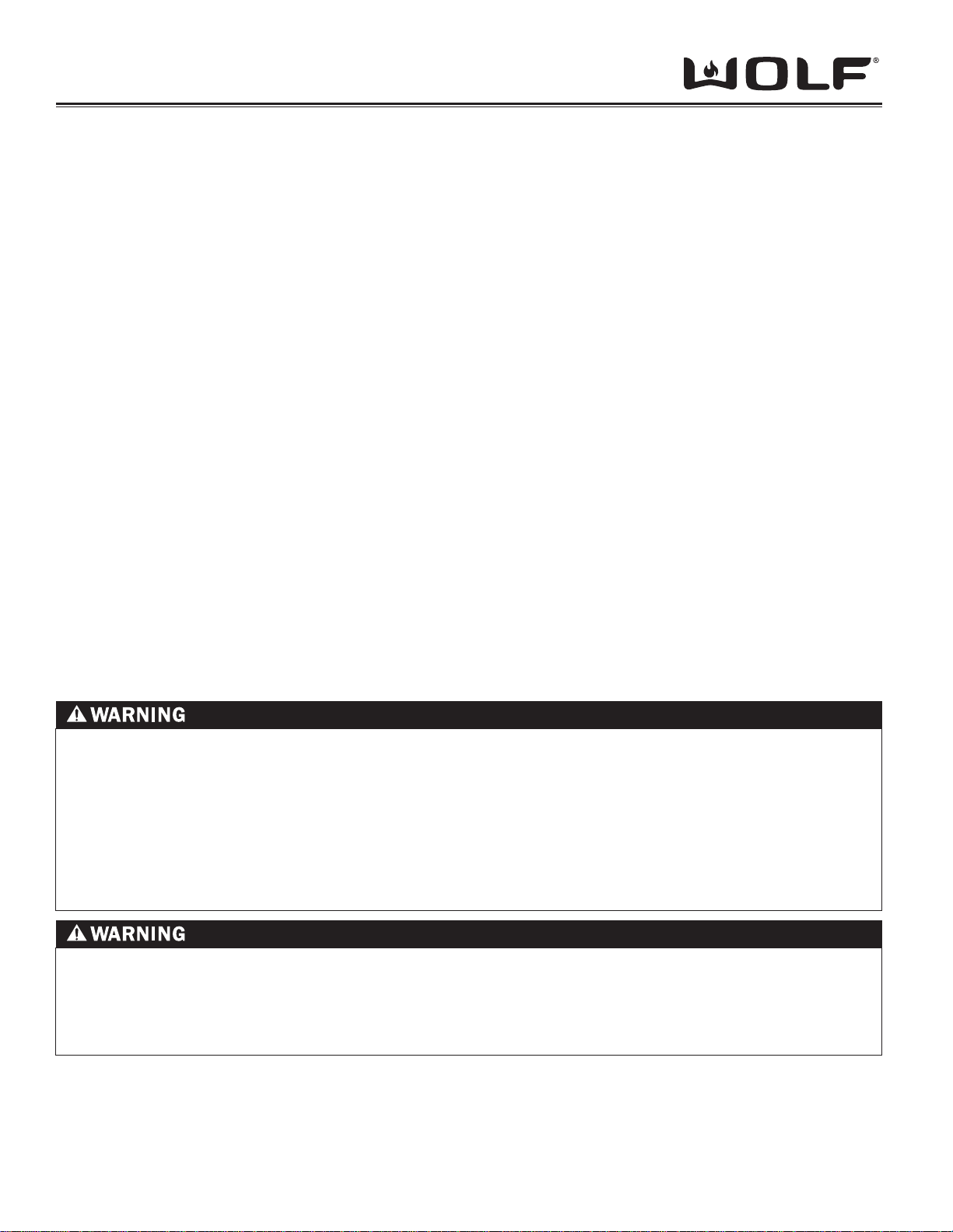
International units come with a terminal box and should
be connected to the residential wiring with the hot leads
connected to positions 1 and 5. The residential ground
lead should be connected to the position marked with the
ground symbol. (See Figure 2-1)
For electrical installation attach the conductors to the
residence wiring in accordance with National Electrical
Codes and all state, provincial, municipal and local
codes.
Site Preparation
NOTE: Installation of the Wolf induction cooktop
must meet the following location requirements. All
dimensions listed are minimum requirements for safe
operation.
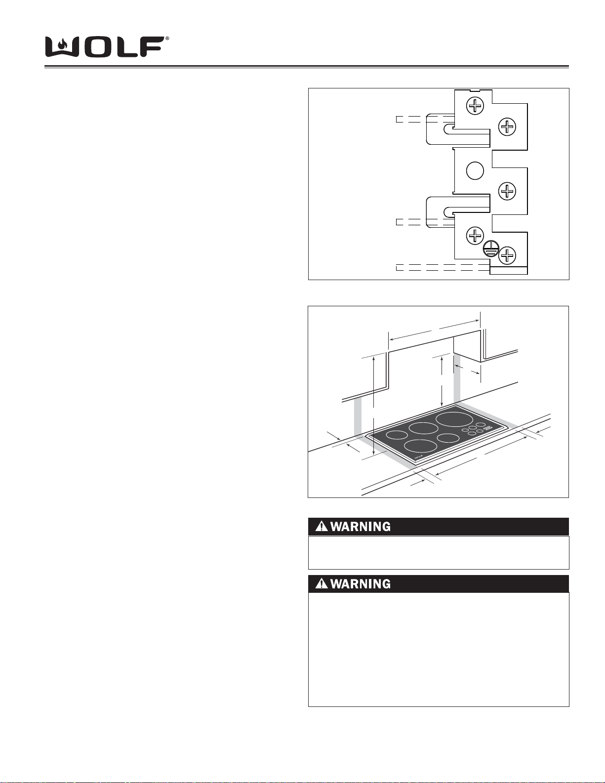
Location In Counter top
See Figure 2-2 for the location of the following letter call
outs.
A. Minimum fl at counter top surface. Must be equal to or
greater than cooktop width.
B. Minimum 1” (25mm) wide clearance from the cooktop
side edge to any combustible surface up to 18”
(457mm) above the cooktop (noted by shaded area).
C. Minimum 1” (25mm) from rear wall.
3
4
L2
5
Ground
Figure 2-1 Terminal Connections (International Units)
F
G
D
E
B
C
A
B
Figure 2-2 Installation Specifi cations
Overhead Cabinet Dimensions
D. Minimum 18” (457mm) vertical distance from the
counter top to the bottom of side cabinets within
minimum side clearance.
E. Minimum vertical distance between the counter top
and combustible materials above the cooktop must be
30” (762mm).
F. Minimum spacing between overhead side cabinets
must be greater than or equal to the nominal width of
the cooktop unit(s).
G. Maximum 13” (330mm) depth of overhead and side
cabinets directly above and within side clearance (See
letter B).
Failure to locate the cooktop without the
proper clearances will result in a fi re hazard.
To eliminate the risk of burns or fi re by
reaching over heated surface units, cabinet
storage space located above the surface
units should be avoided. If cabinet storage
is to be provided, the risk can be reduced
by installing a ventilation hood that projects
horizontally a minimum of 5” (127mm) beyond
the bottom cabinets.
2-3
 Loading...