

Wolf FunctionLine CHK, ComfortLine CHU, FunctionLine CHU, ComfortLine CHU-CB, FunctionLine CHU-CB Installation And Maintenance Instructions Manual
...
Installation and
maintenance instructions
ComfortLine
FunctionLine
Cast iron boilers up to 60 kW
GBPart.-No. 3060918_1203 Subject to modications
Wolf GmbH · Postfach 1380 · 84048 Mainburg · Tel. +49 8751/74-0 · Fax +49 8751/741600 · Internet: www.wolf-heiztechnik.de

2
3060918_1203
Index
Index .......................................................................................................Page
Safety instructions / Reference symbols ......................................................3
Standards / Regulations ............................................................................. 4-5
ComfortLine cast iron boilers ..........................................................................6
FunctionLine cast iron boilers .........................................................................7
Installation ................................................................................................. 8-9
Boiler installation on a plinth .........................................................................10
Boiler installation on a horizontal DHW cylinder ........................................... 11
Boiler assembly ...................................................................................... 12-15
ComfortLine decorative panel installation............................................... 16-17
FunctionLine decorative panel installation....................................................18
Flue pipe installation .....................................................................................19
Central heating to boiler connections ...........................................................20
DHW cylinder to boiler pipework ..................................................................21
Filling the heating system ....................................................................... 22-23
Draining the heating system .........................................................................24
Pressure jet oil burner installation / Electrical supply ...................................25
Initial start-up .......................................................................................... 26-27
Maintenance ........................................................................................... 28-29
Maintenance log ..................................................................................... 30-31
Specication ........................................................................................... 32-33
Dimensions ............................................................................................. 34-35
Troubleshooting ............................................................................................36
33060918_1203
Reference symbols / Safety instructions
The following symbols are used in
conjunction with these important instructions concerning personal safety
and technical reliability.
“Safety instructions“ are
instructions with which you
must comply exactly, to
prevent injury and material
losses.
Danger through “live“ elec-
trical components.
Please note: Switch OFF the
ON/OFF switch before removing the casing.
Never touch electrical com-
ponents or contacts when the
switch is in the ON position.
This creates a risk of electrocution, which may cause
injury or death.
The main supply terminals are
“live“ even when the ON/OFF
switch is in the OFF position.
This indicates technical in-
structions which you must
observe to prevent material
losses and boiler malfunctions.
In addition to the installation instructions,
operating instructions and adhesive labels
are included or tted to the boiler. These
must also be observed.
Note
General
Authorised personnel should read these
instructions before any installation, commissioning or maintenance work.
Adhere to the instructions given in this
document.
Non-observance of these installation
instructions voids any guarantee offered
WOLF.
Safety instructions
• Only use qualied and trained personnel
for the installation, commissioning and
maintenance of the boiler.
• In accordance with DIN EN 50110-1,
work on electrical components (e.g.
control units) may only be carried out
by qualied electricians.
• The regulations of VDE/ÖVE and those
of your local electricity supplier as well
as all other local regulations are applicable to electrical installation work.
• Only operate the boiler within its output
range which is stated in the specication
supplied by WOLF.
• Appropriate use of the boiler refers to
the exclusive use for hot water heating
systems in accordance with DIN 4751.
• Never remove, bypass or otherwise
disable any safety or monitoring equip-
ment.
• The boiler may only be operated in perfect technical condition. Any faults and
damage which may impact on safety
which might limit the safe use of the
equipment must be remedied immediately by a qualied contractor.
• Only replace faulty components or
equipment with original WOLF spare
parts.

4
3060918_1203
Standards / Regulations
Standards and regulations
Observe all current Building Regulations and other local requirements.
Only recognised heating contractors may
install WOLF boilers. This heating contractor will also be responsible for the proper
installation and the commissioning of the
heating system.
The boilers described in these installation
instructions are low temperature boilers
according to HeizAnlV and 92/42/EEC
(Efciency of Hot Water Boilers).
Locate the enclosed operating instructions
in a clearly visible position in the boiler
room.
Boilers may only be installed and operated in boiler rooms which are suitable
according to the Landes-FeuVo [or local
regulations].
The following regulations, rules and guidelines must be observed during installation:
• Boiler room guidelines or Building Regu-
lations relating to the construction and
installation of central boiler rooms and
fuel storage facilities.
• Energy Savings Act (EnEG) and related
directives (Heating Systems Order).
Note: Please read these instructions
carefully before the installation
and keep them in a secure place.
• DIN standards
DIN 1988 Technical rules for DHW
installations
DIN 4701 Rules for
calculating the heat
demand of buildings
DIN 4751 Part 3 - Safety Equipment
for heating systems with ow
temperatures up to 95 °C.
DIN 18160 Domestic chimneys
• VDE requirements:
VDE 0100 General information
regarding the installation of
HV systems with rated
voltages up to 1000V.
VDE 0105 Operation of HV
systems, general
considerations.
VDE 0722 Electrical equipment of
non-electrically heated
heat generators.
VDE 0470/ Protection through
housings
EN 60529
EN 60335-1 Safety of electrical
equipment for domestic
use and similar purposes.
53060918_1203
Standards / Regulations
Cast iron boilers
acc. to DIN EN 303 as well as in accordance with EC Directive 90/396/EEC (gas
consuming equipment),
73/23/EEC (Low Voltage Directive), 89/336/EEC (EMC Directive), 92/42/EEC (Efciency of Hot Water Boilers) and 93/68/EEC (Identication Directive) for heating
systems with heating circuit pumps and ow temperatures up to 110 °C and 3 bar
permissible operating pressure in accordance with DIN 4751 and DHW cylinder pressure (max. 10 bar) in accordance with DIN 4753.
For the operation with pressure jet gas burners, the following gas device categories apply:
The NO
x
limits required by the 1st BImSchV para. 7(2) are maintained.
Country abbreviation Country Gas device category
DE Germany II
2ELL3B/P
AT Austria II
2H3B/P
LU Luxembourg I2E or I
3+
6
3060918_1203
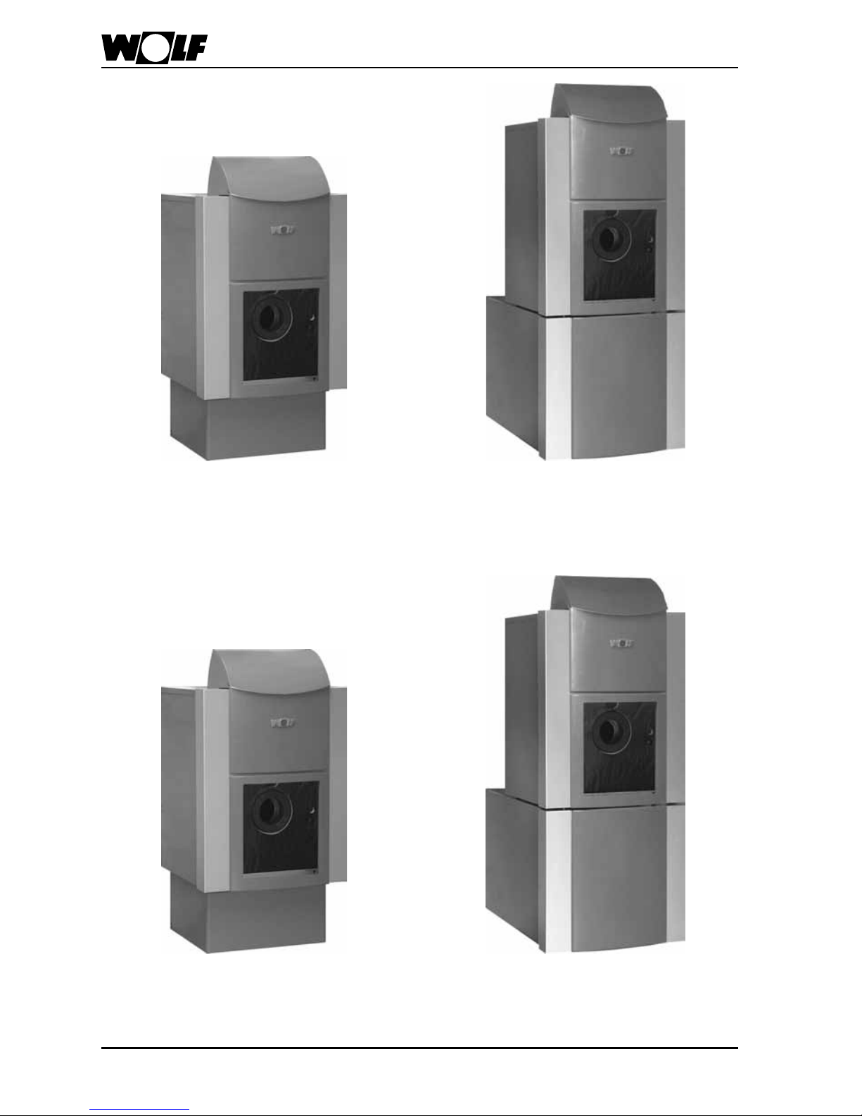
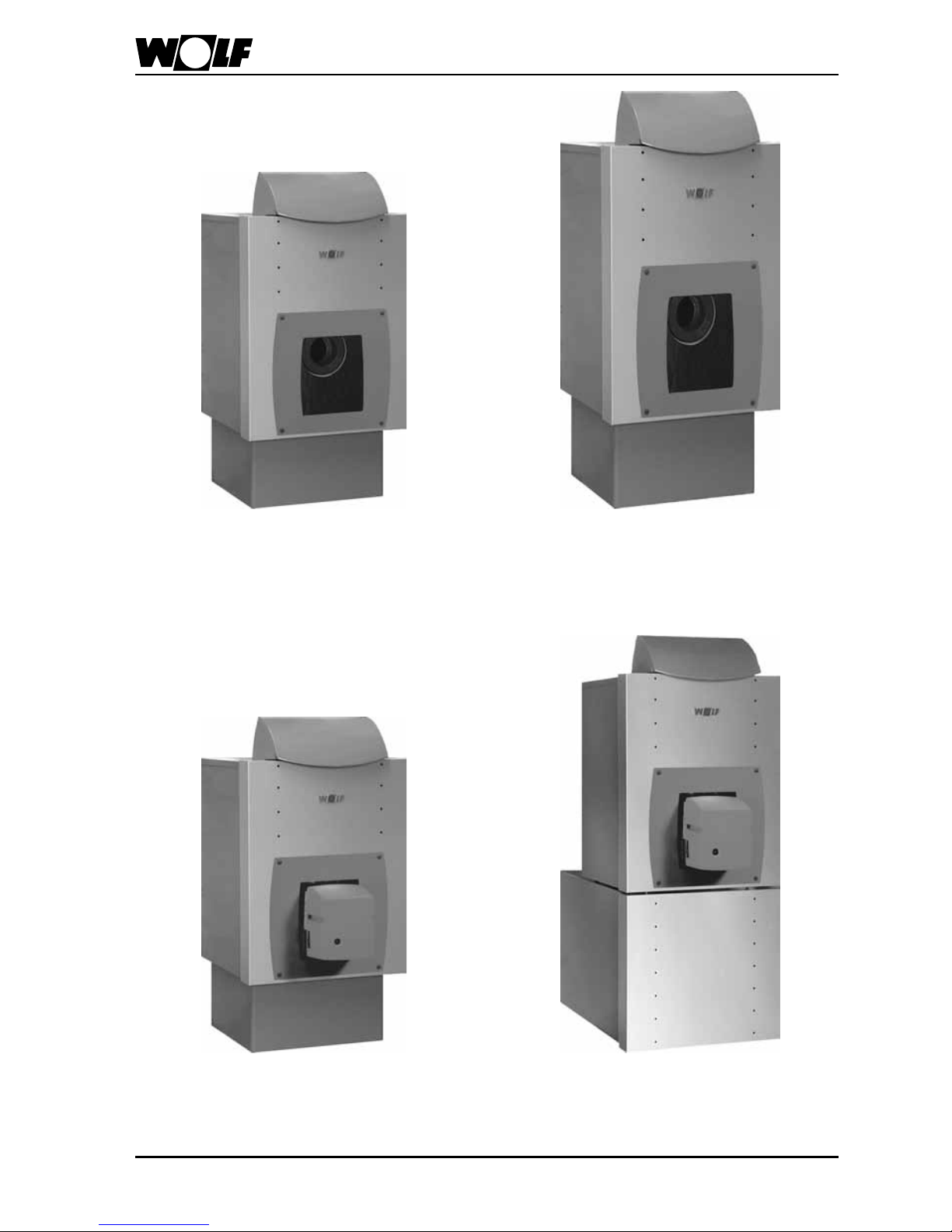
ComfortLine cast iron boilers
Oil and gas-red cast iron boilers, type
CHK
(boiler plinth, accessory)
Oil and gas-red cast iron boilers, type
CHK-CB
incl. DHW cylinder
Oil-red cast iron Unit boiler, type CHU
incl. pressure jet oil burner
(boiler plinth, accessory)
Oil-red cast iron Unit boiler, type CHU-CB
incl. DHW cylinder
and pressure jet oil burner
73060918_1203
FunctionLine cast iron boilers
Oil and gas-red cast iron boilers, type FHK
(boiler plinth, accessory)
Oil and gas-red cast iron boilers, type
FNK-FB/FE incl. DHW cylinder
Oil-red cast iron Unit boiler, type FHU
incl. pressure jet oil burner
(boiler plinth, accessory)
Oil-red cast iron Unit boiler, type FHU-FB/FE
incl. DHW cylinder
and pressure jet oil burner
8
3060918_1203
Installation
The ventilation air supply must
be ensured and comply with
local regulations or those relating to gas installations. We
recommend that you supply the
boiler with fresh air directly from
the outside. An insufcient fresh
air supply can lead to fuel gas
escaping, which represents
a risk to life (poisoning/suffocation).
Clearances towards walls and
combustible materials must
comply with local re regulations, and should be at least
200mm, otherwise there is a
high risk of re.
General tips regarding location
• Install the boiler with or without the
DHW cylinder on a level surface which
is substantial enough to carry its weight.
• Position the boiler and DHW cylinder (if
installed) horizontally or slightly rising
towards the back to ensure adequate
venting of any trapped air (level with
adjustable feet).
Only install the boiler and DHW
cylinder (if installed) in a room
safe from the risk of frost.
Drain the boiler, the DHW
cylinder and the entire heating
system if there is a risk of frost,
when the system has been
shutdown, to prevent pipes
from bursting.
Boilers should not be installed
in areas subject to aggressive
vapours, very dusty or highly
humid conditions (workshops,
washrooms, hobby rooms etc.).
This prevents the optimum
burner function from being
achieved.
The combustion air supplied to
the pressure jet oil burner must
be free from halogenated hydrocarbons (e.g. as contained
in sprays, solvents, cleaning
uids, paints and adhesives).
Under the most unfavourable
conditions, these may lead to
pitting of the boiler and even
the ue gas system.
Never store or use combustible
material or liquids near the
boiler.
Note
Note
93060918_1203
Installation
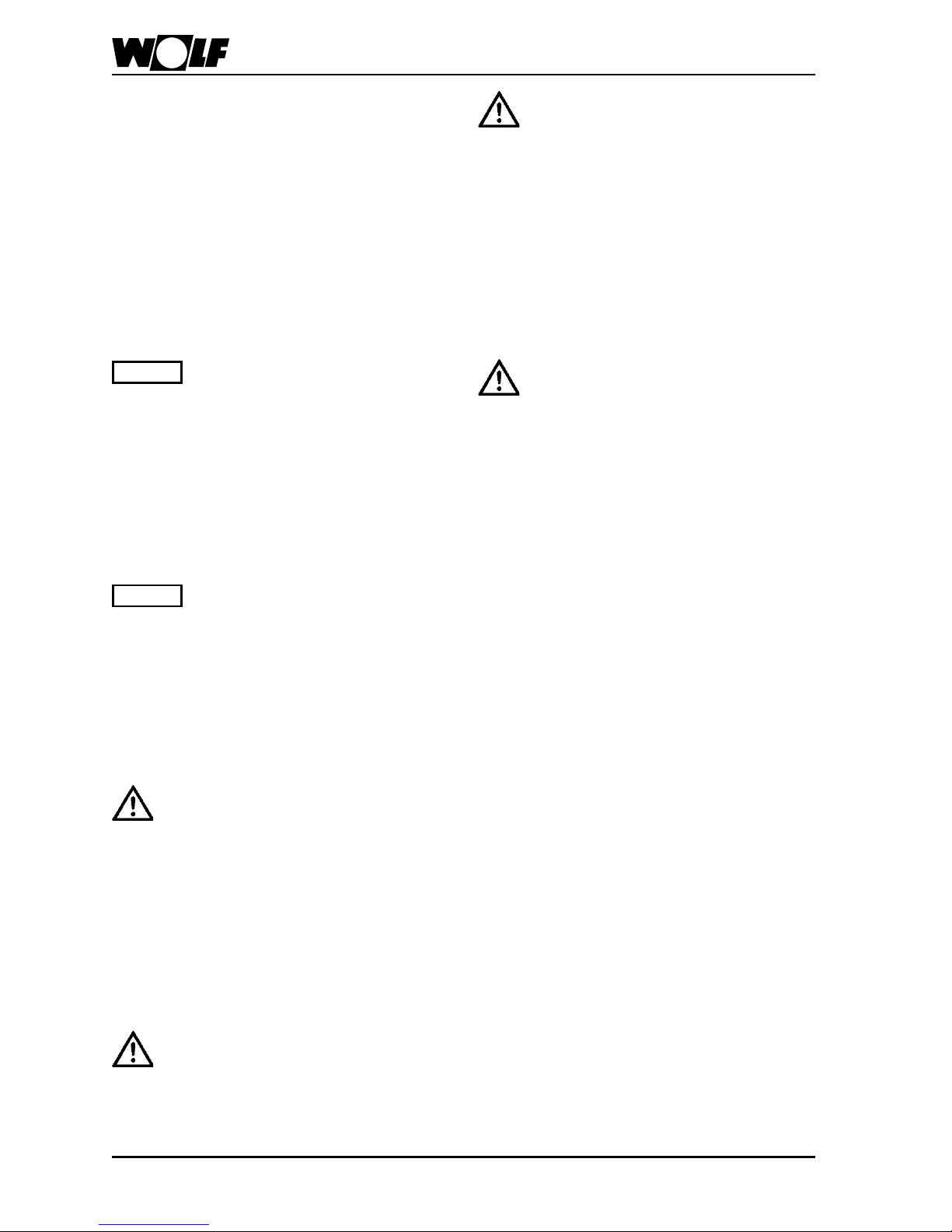
Recommended minimum wall
clearance
Maintain a minimum clearance between
the boiler sides and walls of 400 mm to
enable the boiler door with tted burner
to be opened.
Ensure that sufcient space is available
for cleaning and maintenance.
1000
900
400
Recommended minimum wall clearance
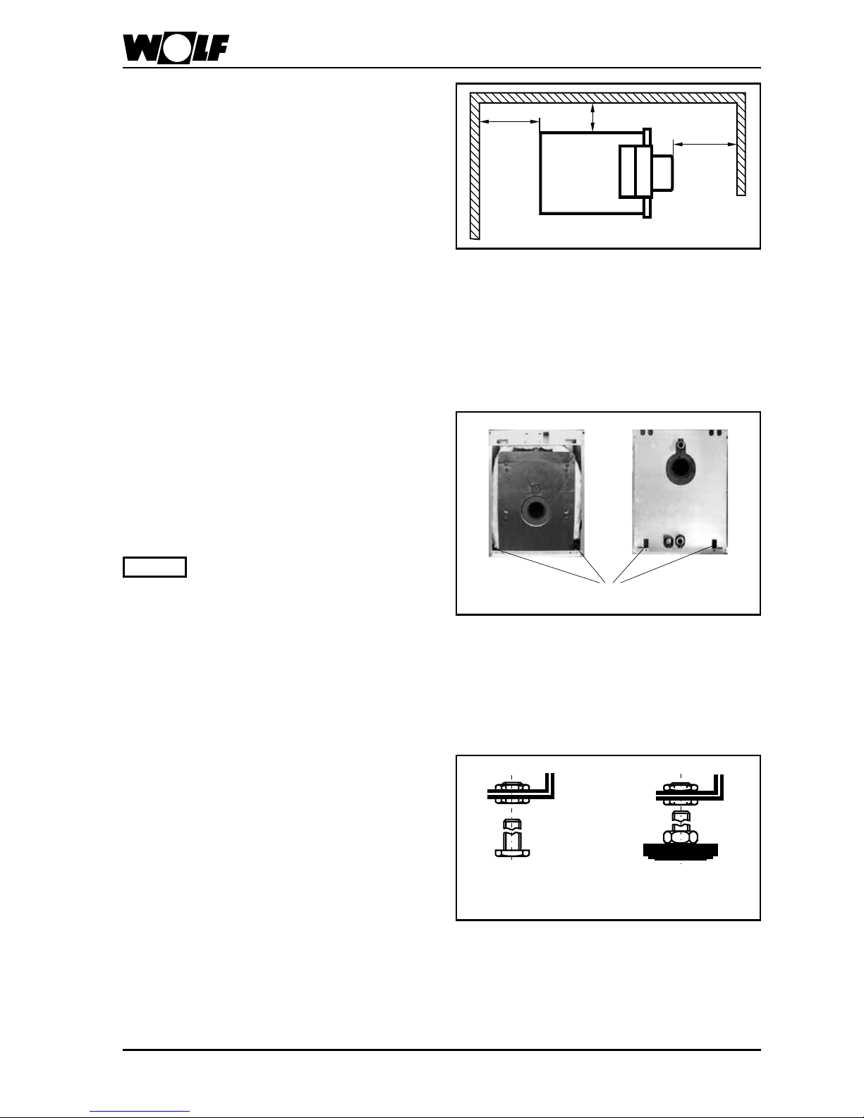
Transportation into the boiler
room
To ease the transportation into the boiler
room, lifting slings with lifting hooks are
offered as accessories.
Only lift the boiler using all four
lifting slings.
Note
Lifting eyes for lifting slings
Boiler installation on adjustable feet
At the factory the boiler is equipped with
four adjustable bolts
• Level the boiler with adjustable feet
(accessory) horizontally or with a slight
incline to the rear.
Feet
(accessory)
Adjustable
bolt
Adjustable bolt/ feet
10
3060918_1203
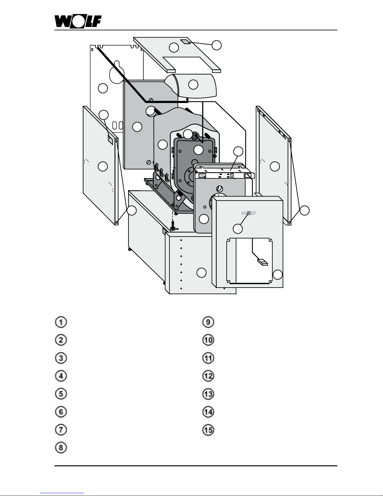
15
11 11
4
8
10
6 6
3
5
7
2
1
13
13
14
12
9
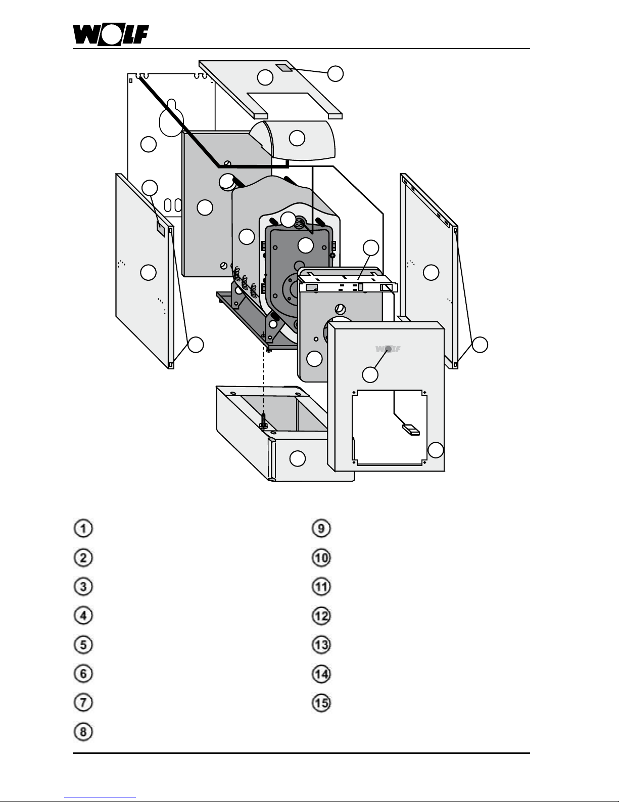
Boiler installation on a plinth
Boiler
Boiler door
Thermal insulation, boiler
Thermal insulation, boiler back
Thermal insulation, boiler front
Side casing
Control unit bracket
Back wall casing
Control unit housing
Casing cover
Spring shackles
Front casing
Type plate
Wolf logo
Plinth (accessory)
113060918_1203
15
11 11
4
8
10
6 6
3
5
7
2
1
13
13
14
12
9
Boiler installation on a horizontal
DHW cylinder
Boiler
Boiler door
Thermal insulation, boiler
Thermal insulation, boiler back
Thermal insulation, boiler front
Side casing
Control unit bracket
Back wall casing
Control unit housing
Casing cover
Spring shackles
Front casing
Type plate
Wolf logo
Horizontal DHW cylinder
 Loading...