


 Loading...
Windsor CS24SP 10060220, CSE24 10060250, CSXEO24 10060300, CSX24 10060270, CSE24SP 10060260 User Manual
...iSCRUB |
|
|
|
|
|
|
Operating Instructions (ENG) |
MODELS: |
CS24 |
CSE24 |
CS24SP |
|
10060210 |
10060250 |
10060220 |
|
CSX24 |
CSXE24 |
CSE24SP |
|
10060270 |
10060290 |
10060260 |
|
CSXEO24 |
|
|
|
10060300 |
|
|
Read these instructions before using the machine
CP
86037660 05/27/08
PRV NO. 980228

MACHINE DATA LOG/OVERVIEW
MODEL _______________________________________
DATE OF PURCHASE __________________________
SERIAL NUMBER ______________________________
SALES REPRESENTATIVE # _____________________
YOUR DEALER
Name: __________________________________________________________________________________________________
Address: _______________________________________________________________________________________________
Phone Number: _________________________________________________________________________________________
OVERVIEW
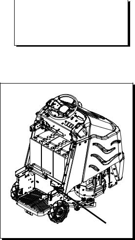
The Chariot Scrubber is a battery powered, stand-on, hard floor scrubber intended for commercial use. The appliance applies a cleaning solution onto a hard floor, scrubs the floor with brushes or pads, and then vacuums the soiled water back into the recovery tank.
2 |
86037660 CHARIOT 11/09/06 |
Machine Data Log/Overview................................ |
2 |
Table Of Contents ................................................ |
3 |
HOW TO USE THIS MANUAL |
|
How To Use This Manual..................................... |
1-1 |
SAFETY |
|
Important Safety Instructions ............................ |
2-1 |
Hazard Intensity Level....................................... |
2-2 |
Safety Label Location........................................ |
2-3 |
OPERATIONS |
|
Technical Specifications.................................... |
3-1 |
How The Machine Works. ................................. |
3-3 |
Components ...................................................... |
3-4 |
Drive Controls.................................................... |
3-5 |
Scrub Controls-Basic & Cylindrical ................... |
3-9 |
Scrub Controls-Deluxe ...................................... |
3-11 |
Scrub Controls-Squeegee................................. |
3-13 |
Machine Operation............................................ |
3-15 |
Pre-Run Machine Inspection........................ |
3-15 |
Starting Machine .......................................... |
3-15 |
Emergency Stop Procedures ....................... |
3-15 |
Filling Solution Tank ..................................... |
3-16 |
Normal Scrubbing......................................... |
3-16 |
To Begin Scrubbing...................................... |
3-17 |
Priming Pump............................................... |
3-17 |
To Stop Scrubbing........................................ |
3-18 |
Double Scrub................................................ |
3-18 |
Emptying And Cleaning Tanks..................... |
3-19 |
MAINTENANCE |
|
Service Schedule .............................................. |
4-1 |
Batteries. ........................................................... |
4-2 |
Squeegee.......................................................... |
4-6 |
Scrub Brushes................................................... |
4-9 |
Scrub Deck-Disk................................................ |
4-10 |
Scrub Deck-Cylindrical...................................... |
4-13 |
Circuit Protection............................................... |
4-18 |
Solution Strainer & Pump-Disk.......................... |
4-19 |
Solution Strainer & Pump-Cylindrical................ |
4-20 |
Vacuum & Float Shut-Off .................................. |
4-22 |
Drive Motor & Brake.......................................... |
4-24 |
Bag Replacement.............................................. |
4-27 |
Transporting Machine........................................ |
4-28 |
Machine Troubleshooting.................................. |
4-29 |
TABLE OF CONTENTS
GROUP PARTS LIST |
|
Bumper .............................................................. |
5-1 |
Control Panel-Basic-Cylindrical......................... |
5-3 |
Control Panel-Deluxe ........................................ |
5-5 |
Control Panel Housing....................................... |
5-7 |
Decal.................................................................. |
5-9 |
Frame-Lower ..................................................... |
5-11 |
Frame-Upper ..................................................... |
5-13 |
Pedal Platform ................................................... |
5-15 |
Rear Cover ........................................................ |
5-19 |
Scrub Brush/Pad Driver..................................... |
5-21 |
Scrub Deck - Disk.............................................. |
5-23 |
Scrub Deck – Cylindrical ................................... |
5-25 |
Scrub Deck Aqua-Mizer™................................. |
5-27 |
Side Squeegee – Cylindrical ............................. |
5-29 |
Scrub deck – Side Squeegee – Cylindrical ....... |
5-31 |
Scrub Deck Skirts .............................................. |
5-33 |
Scrub Deck Lift .................................................. |
5-35 |
Scrub Deck MountingCylindrical ..................... |
5-37 |
Scrub Deck Actuator – Cylindrical..................... |
5-39 |
Solution Cylindrical ............................................ |
5-41 |
Solution Disk...................................................... |
5-43 |
Squeegee - Disk ................................................ |
5-45 |
Squeegee – Cylindrical...................................... |
5-47 |
Squeegee Lift-Basic .......................................... |
5-49 |
Squeegee Lift-Deluxe ........................................ |
5-51 |
Squeegee Swing ............................................... |
5-53 |
Squeegee Lift – Cylindrical................................ |
5-55 |
Steering ............................................................. |
5-59 |
Tank................................................................... |
5-61 |
Vacuum.............................................................. |
5-63 |
Wheel-Front Drive, Chain .................................. |
5-65 |
Wheel-Front Drive, Gear ................................... |
5-67 |
Wheel-Front Brake ............................................ |
5-69 |
Wheel-Rear........................................................ |
5-71 |
Wiring-Batteries ................................................. |
5-73 |
Wiring-Components........................................... |
5-75 |
Wiring-Control Panel-Basic-Cylindrical ............. |
5-77 |
Wiring-Control Panel-Deluxe............................. |
5-79 |
Wiring-Drive Motor............................................. |
5-81 |
Wiring-Main Harness ......................................... |
5-83 |
Wiring-Pedal Platform........................................ |
5-85 |
Wiring Diagram-Basic-Cylindrical...................... |
5-87 |
Wiring-Diagram-Deluxe ..................................... |
5-88 |
Hose Diagram-Disk ........................................... |
5-89 |
Hose Diagram-Cylindrical.................................. |
5-90 |
Suggested Spare Parts ..................................... |
5-91 |
OPTIONS |
|
Back-Up Alarm – Option.................................... |
6-1 |
Battery Cart – Option......................................... |
6-3 |
Seat – Option..................................................... |
6-7 |
Warning Light – Option...................................... |
6-9 |
EC Declaration of Conformity ............................ |
6-11 |
Serial Numbers.................................................. |
6-14 |
Warranty |
|
86037660 CHARIOT 04/15/08 |
3 |
HOW TO USE THIS MANUAL
This manual contains the following sections: |
The SAFETY section contains important information |
|
|
|
regarding hazard or unsafe practices of the |
- HOW TO USE THIS MANUAL |
machine. Levels of hazards are identified that could |
|
- |
SAFETY |
result in product or personal injury, or severe injury |
- |
OPERATIONS |
resulting in death. |
-MAINTENANCE
|
- PARTS LIST |
The OPERATIONS section is to familiarize the |
||||
|
|
|
|
|
operator with the operation and function of the |
|
The HOW TO USE THIS MANUAL section will tell |
machine. |
|
||||
you how to find important information for ordering |
|
|
||||
correct repair parts. |
The MAINTENANCE section contains preventive |
|||||
|
|
|
|
|
maintenance to keep the machine and its |
|
Parts may be ordered from authorized Windsor |
components in good working condition. They are |
|||||
dealers. When placing an order for parts, the |
listed in this general order: |
|||||
machine model and machine serial number are |
|
|
||||
important. Refer to the MACHINE DATA box which |
- |
Batteries |
||||
is filled out during the installation of your machine. |
- |
Scrub Brushes |
||||
The MACHINE DATA box is located on the inside of |
- |
Adjusting Squeegee |
||||
the front cover of this manual. |
- |
Service Schedule |
||||
|
|
|
|
|
- |
Machine Troubleshooting |
|
|
|
|
|
The PARTS LIST section contains assembled parts |
|
|
|
|
|
|
||
|
MODEL _____________________________________ |
|||||
|
illustrations and corresponding parts list. The parts |
|||||
|
DATE OF PURCHASE ________________________ |
|||||
|
lists include a number of columns of information: |
|||||
|
|
|
|
|
||
SERIAL |
NUMBER ____________________________ |
|
|
SALES REPRESENTATIVE # ___________________ |
- REF – column refers to the reference |
||
|
|
|
number on the parts illustration. |
|
|
- PART NO. – column lists the part |
|
|
|
|
number for the part. |
The model and serial number of your machine are |
- |
PRV NO. - Reference No. |
|
located below the battery compartment of the |
- QTY – column lists the quantity of the |
||
machine. |
|
|
part used in that area of the machine. |
|
|
- DESCRIPTION – column is a brief |
|
|
|
|
description of the part. |
|
|
- SERIAL NO. FROM – If this column has |
|
|
|
|
an (*) and a Reference number, see the |
|
|
|
SERIAL NUMBERS page in the back of |
|
|
|
your manual. If column has two asterisk |
|
|
|
(**), call manufacturer for serial number. |
|
|
|
The serial number indicates the first |
|
|
|
machine the part number is applicable |
|
|
|
to. The main illustration shows the most |
|
|
|
current design of the machine. When a |
|
|
|
boxed illustration is shown, it displays |
|
|
|
the older design. |
|
|
- NOTES – column for information not |
|
|
|
|
noted by the other columns. |
|
|
NOTE: If a service or option kit is installed on your |
|
|
|
machine, be sure to keep the KIT INSTRUCTIONS |
|
|
|
which came with the kit. It contains replacement |
|
|
|
parts numbers needed for ordering future parts. |
|
|
|
NOTE: The number on the lower left corner of the |
|
|
|
front cover is the part number for this manual. |
|
1-1 |
86037660 CHARIOT 04/15/08 |
|
|

IMPORTANT SAFETY INSTRUCTIONS
When using an battery powered appliance, basic precaution must always be followed, including the following:
READ ALL INSTRUCTIONS BEFORE USING THIS MACHINE.
To reduce the risk of fire, electric shock, or injury:
Use only indoors. Do not use outdoors or expose to rain.
Use only as described in this manual. Use only manufacturer’s recommended components and attachments.
If the machine is not working properly, has been dropped, damaged, left outdoors, or dropped into water, return it to an authorized service center.
Do not operate the machine with any openings blocked. Keep openings free of debris that may reduce airflow. This machine is not suitable for picking up hazardous dust.
Machine can cause a fire when operating near flammable vapors or materials. Do not operate this machine near flammable fluids, dust or vapors.
This machine is suitable for commercial use, for example in hotels, schools, hospitals, factories, shops and offices for more than normal housekeeping purposes.
Maintenance and repairs must be done by qualified personnel.
If foam or liquid comes out of machine, switch off immediately.
Disconnect battery before cleaning or servicing.
Before the machine is discarded, the batteries must be removed and properly disposed of. Make sure all warning and caution labels are legible and properly attached to the machine.
During operation, attention shall be paid to other persons, especially children.
Before use all covers and doors shall be put in the positions specified in the instructions.
When leaving unattended, secure against unintentional movement.
The machine shall only be operated by instructed and authorized persons.
When leaving unattended, switch off or lock the main power switch to prevent unauthorized use.
Only chemicals recommended by the manufacturer shall be used.
This appliance has been designed for use with the brushes specified by the manufacturer. The fitting of other brushes may affect its safety.
Do not use on surfaces having a gradient of over 10% (6 degrees).
SAVE THESE INSTRUCTIONS
86037660 CHARIOT 11/09/06 |
2-1 |

HAZARD INTENSITY LEVEL
The following symbols are used throughout this guide as indicated in their descriptions:
HAZARD INTENSITY LEVEL
There are three levels of hazard intensity identified by signal words -WARNING and CAUTION and FOR SAFETY. The level of hazard intensity is determined by the following definitions:
WARNING - Hazards or unsafe practices which COULD result in severe personal injury or death.
CAUTION - Hazards or unsafe practices which could result in minor personal injury or product or property damage.
FOR SAFETY: To Identify actions which must be followed for safe operation of equipment.
Report machine damage or faulty operation immediately. Do not use the machine if it is not in proper operating condition. Following is information that signals some potentially dangerous conditions to the operator or the equipment. Read this information carefully. Know when these conditions can exist. Locate all safety devices on the machine. Please take the necessary steps to train the machine operating personnel.
FOR SAFETY:
DO NOT OPERATE MACHINE:
Unless Trained and Authorized.
Unless Operation Guide is Read and understood.
In Flammable or Explosive areas.
In areas with possible falling objects.
WHEN SERVICING MACHINE:
Avoid moving parts. Do not wear loose clothing; jackets, shirts, or sleeves when working on the machine. Use Windsor approved replacement parts.
Batteries emit hydrogen gas. Explosion or fire can result. Keep sparks and open flame away. Keep solution tank in raised position when charging. Keep sparks and flames away from the batteries. Do not smoke around batteries.
Disconnect batteries before working on machine. Only qualified personnel should work inside machine. Always wear eye protection and protective clothing when working on or near batteries. Avoid skin contact with the acid contained in the batteries.
Never allow metal to lie across battery tops.
2-2 |
86037660 CHARIOT 11/09/06 |

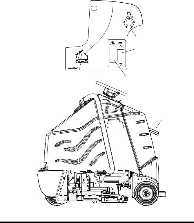
SAFETY LABEL LOCATION
NOTE: These drawings indicate the location of safety labels on the machine. If at any time the labels become illegible, promptly replace them.
86244300 PRV NO. 500955 WARNING LABEL
86252520 PRV NO. 80885 BATTERY CAUTION
86037660 CHARIOT 11/09/06 |
2-3 |
TECHNICAL SPECIFICATIONS
ITEM |
DIMENSION/CAPACITY |
Nominal power |
2100 W |
Rated Voltage |
36 Volts DC |
Rated Amperage |
58 amps |
Batteries |
3 X12 Volt 195-215 AH @ 20 hr. rate |
|
21 in. x 16 in. x 17 in. tall |
Battery Compartment Dimensions |
(533mm x 406mm x 432mm) |
Scrub Brush Motors - Disk Machine |
2 x .3 HP (190 W) |
Scrub Brush Motors - Cylindrical Machine |
2 x .75 HP (560 W) |
Vacuum Motor(s) |
.75 HP (560 W) |
Maximum flow rate of vacuum motor |
77.0 cfm (36.4 liters per second) |
Maximum suction of vacuum motor |
81.8 inches of water (20.3 kPa) |
Propelling Motor |
.75 HP (560 W) |
Mass (GVW) |
1245 lbs (565 kg) |
Weight empty without batteries |
535 lbs (243 kg) |
|
1.3 GPM pump, fully variable with automatic shut-off |
Solution Control |
in neutral |
Solution capacity |
25 gal (95 L) |
Recovery capacity |
25 gal (95 L) |
Scrub brush diameter - Disk Machine |
12 inch (305 mm) |
Scrub brush diameter - Cylindrical Machine |
6 inch (152 mm) |
Scrub brush pressure |
0-150lbs (0-667N) |
Scrub brush speed - Disk Machine |
300 rpm |
Scrub brush speed - Cylindrical Machine |
800 rpm |
Tires |
10 in. (254mm) Solid Scrubber Compound |
Foundation Pressure |
104 psi (715 Kpa) |
Maximum Speed |
3.5 miles/hour (5.6 Km/hour) |
Theoretical Coverage |
24,200 ft /hr @ 2.5 mph with 2 in. overlap |
Frame Construction |
Powder coated steel |
|
Electrical parking brake, sets automatically whenever |
Brake |
operator steps off platform or engages emergency |
stop. |
|
Minimum aisle u-turn width |
56 in. (1425 mm) |
Maximum rated climb and descent angle |
7.5 degrees |
3-1 |
86037660 CHARIOT 11/09/06 |
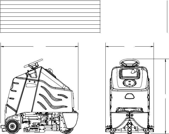
ITEM
Height
Length
Width without squeegee
Width of squeegee - Disk Machine
Width of squeegee - Cylindrical Machine
Width of scrub path - Disk Machine
Width of scrub path - Cylindrical Machine
LENGTH
TECHNICAL SPECIFICATIONS
MEASURE
50.6inches (1285 mm)
52.5inches (1330 mm)
26.5inches (670 mm)
32.7inches (830 mm) 29 inches (737 mm) 24 inches (610 mm) 23 inches (585 mm)
WIDTH |
HEIGHT |
SPECIAL NOTES:
The sound pressure level at the operator’s ear was measured to be 68 dBA. This was a nearfield, broadband measurement taken in a typical industrial environment on a tile floor. This appliance contains no possible source of impact noise. The instantaneous sound pressure level is below 63 Pa.
The weighted root mean square acceleration at the operator’s arms was measured to be below 2.5m/s2 . This was a tri-axial, third-octave-band measurement made during normal operation on a composite tile floor. The measurement and related calculations were made in accordance with ANSI S3.34-1986.
This appliance is not intended for use by persons (including children) with reduced physical, sensory or mental capabilities, or lack of experience and knowledge, unless they have been given supervision or instruction concerning use of the appliance by a person responsible for their safety. Children should be supervised to ensure that they do not play with the appliance.
86037660 CHARIOT 03/27/08 |
3-2 |
HOW THIS MACHINE WORKS
The Chariot® is a battery powered, self-propelled, hard floor scrubber intended for commercial use. The appliance applies a cleaning solution onto a hard floor, scrubs the floor with brushes, and then vacuums the soiled water back into the recovery tank.
The machine's primary systems are the solution system, scrub system, recovery system, and operator control system.
The function of the solution system is to store cleaning solution and deliver it to the scrub system. The solution system consists of the solution tank, strainer, pump, valve and controls. The solution tank stores cleaning solution (water and detergent) until it is delivered to the scrub system. The strainer protects the pump from debris. The valve automatically prevents solution flow unless the scrub brushes are turned on and the machine is being propelled. The solution control switch controls the amount of cleaning solution delivered to the scrub system by controlling the amount of time the pump is on.
The function of the scrub system is to scrub the floor. The disk scrub system consists of two rotary type disk scrub brushes, motors, scrub deck skirt, lift actuator and controls. The brushes scrub the floor as the motors drive the brushes. The brush drive hubs allow the scrub brushes to follow irregularities and changes in the floor without loosing contact with the floor. The scrub deck skirts control the cleaning solution on the floor so that the squeegee can pick it up. The one touch/brush switch controls the motors and lift actuator to turn the motors on and lower the deck, or turn the motors off and raise the deck. The brush pressure switch controls the down pressure on the scrub deck.
The scrub plus system consists of two cylindrical type brushes, motors, scrub deck side squeegees, hopper, lift actuator, and controls. The cylindrical scrub head is designed to eliminate debris that may be caught in the squeegee while scrubbing. Water is applied to the first scrubbing brush turning in a clockwise rotation when viewed from the right side of machine. The first brush scrubs dirt and debris between the brushes. The second scrubbing brush, turning in a counter clockwise rotation, picks up debris and throws it into a removable hopper. Water is allowed to drain out the hopper into the squeegee path where it is recovered from the floor.
The scrub deck side squeegees control the cleaning solution on the floor so that the squeegee can pick it up. The brush pressure switch controls the motors and lift actuator to turn the motors on and lower the deck, or turn the motors off and raise the deck. The brush pressure switch also controls the down pressure on the scrub deck.
The function of the recovery system is to vacuum the soiled water back into the recovery tank. The recovery system consists of the squeegee, vacuum motor, float ball filter, recovery bag and controls. The squeegee wipes the dirty solution off the floor as the machine moves forward. The vacuum motor provides suction to draw the dirty solution off the floor and into the recovery bag. The float ball filter protects the vacuum fan from debris and foam. The recovery bag stores the dirty solution.
The function of the operator control system is to control the direction and speed of the machine. The directional control system consists of the direction control switch, throttle pedal, operator presence pedal, speed control switch, drive reset switch, emergency stop/brake switch, steering wheel, propel controller, and drive wheel. The directional control switch signals forward or reverse direction. The controller interprets signals from the throttle pedal to command the drive wheel to propel or slow the machine. The drive reset switch is to make sure the operator is on platform before machine will propel. The operator presence pedal is to make sure the operator keeps both feet safely on platform while driving. The steering wheel points the drive wheel in the direction desired by the operator. The parking brake automatically engages when the operator steps off the platform. The emergency stop/brake can be used to hold the machine on slopes.
3-3 |
86037660 CHARIOT 11/09/06 |
COMPONENTS
2
1 |
7 |
3
11
5
6
12
10
4 |
9 |
8
1. |
Control Panel-Drive |
7. |
Recovery Dome |
2. |
Control Panel-Scrub |
8. |
Recovery Drain Hose |
3. |
Control Housing |
9. |
Scrub Deck Aqua-Mizer |
4. |
Pedal Platform |
10. |
Scrub Deck Skirts/Side Squeegees |
5. |
Rear Cover |
11. |
Solution Cover |
6. |
Tank |
12. |
Solution Drain Hose |
86037660 CHARIOT 11/09/06 |
3-4 |
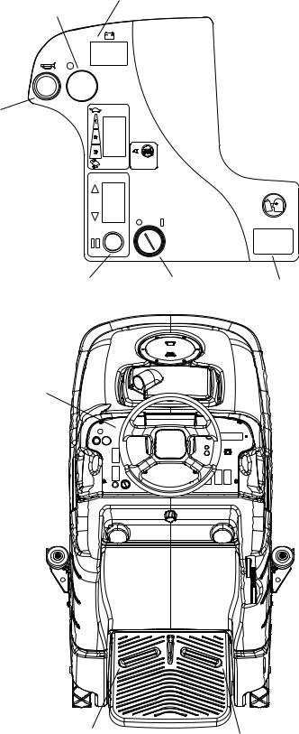
DRIVE CONTROLS
10 (Basic)
2
8
6 
3
7 |
1 |
11 (Basic) |
9
5
4
3-5 |
86037660 CHARIOT 11/09/06 |

|
|
|
DRIVE CONTROLS |
1. |
Key Switch |
7. |
Drive Reset Button |
2. |
Emergency Stop/Brake Switch |
8. |
Horn Button |
3. |
Directional Control Switch |
9. |
Steering Wheel |
4. |
Throttle Pedal |
10. |
Battery Discharge |
5. |
Operator Presence Pedal |
|
Indicator (Basic Only) |
6. |
Speed Control Switch |
11. |
Hour Meter (Basic Only) |
1.KEY SWITCH
Controls the power for machine functions.
To turn the machine power on, rotate key clockwise. To turn the machine off, rotate key counterclockwise.
Deluxe Only: When the key is turned on the battery symbol will flash while the system runs self-diagnostics and returns scrub deck and squeegee to their raised positions, if necessary. The controller will not respond to other commands until this routine is complete.
2.EMERGENCY STOP/BRAKE SWITCH
This safety feature is designed to cut all power to the machine at any time and apply parking brake.
To shut the machine power off, push the Emergency Stop Switch, this will also engage the parking brake and cause the machine to stop immediately.
To reset the machine, rotate the switch clockwise.
3.DIRECTIONAL CONTROL SWITCH
Controls the direction of travel of the vehicle. The position of the switch indicates direction of travel. To travel forward, press the top of the switch.
To travel in reverse, press the bottom of the switch.
4.THROTTLE PEDAL
Controls the speed of the vehicle within the speed control setting selected. Pressing the pedal causes the machine to travel in the direction selected by the Directional Control Switch.
To increase speed, increase pressure on the pedal. To decrease speed, decrease pressure on the pedal.
5.OPERATOR PRESENCE PEDAL
This safety feature is designed to ensure that the operator has their left foot on pedal platform whenever machine is moving. The operator must have left foot on Operator Presence Pedal for machine to move.
86037660 CHARIOT 11/09/06 |
3-6 |
DRIVE CONTROLS
6.SPEED CONTROL SWITCH
Controls the maximum speed of the machine. There are two setting intended for scrubbing, speeds 1 and 2. Speed 3 is recommended for transport only, not scrubbing.
To increase speed, press the top of the switch.
To decrease speed, press bottom of the switch. Speeds can be adjusted at any time, whether machine is moving or not.
Basic: The position of the switch indicates speed setting.
Deluxe: The display indicates speed setting. When the key is turned on the controller will automatically adjust the speed to setting 2.
7.DRIVE RESET SWITCH
This safety feature is designed to ensure safe engagement of propel drive. Each time the machine power is turned on, and each time an operator steps on to the platform, the Drive Reset Switch must be pushed before machine will propel.
8.HORN BUTTON
The horn is activated by pressing the horn button.
9.STEERING WHEEL
The steering wheel turns the front wheel causing the machine to change direction.
3-7 |
86037660 CHARIOT 11/09/06 |
DRIVE CONTROLS
10A. BATTERY CHARGE LEVEL INDICATOR-BASIC
Indicates the charge level of the batteries.
The meter display is divided into 10 vertical bars. Bars illuminated on the far right indicate full charge. Bars flashing near the left side indicate the batteries should be recharged. Further operation of the machine could damage the machine or the batteries.
When the machine is left overnight with less than a full charge, the display may initially indicate a full charge. It will also indicate a full charge if the batteries are disconnected, then reconnected. After a few minutes of operation the meter will give the correct charge level.
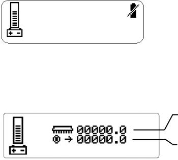
10B. BATTERY CHARGE LEVEL INDICATOR-DELUXE
The battery meter can be viewed at the left side of either information screen 1 or information screen 2. The level of battery charge is indicated by the horizontal bars in the battery meter box. When the batteries require charging, the icon will flash and a battery inhibit icon will appear on the right side of either information screen. Scrub and solution functions that are running when the battery inhibit icon appears will be automatically shut off. It is not possible to restart scrub functions while the battery inhibit is displayed. The controller reserves enough battery charge to allow pick-up of residual water and transport back to a charging station.
11A. HOUR METER-BASIC
Records the number of hours the machine has been in operation. This information is useful in determining when to service the machine.
11B. HOUR METER-DELUXE
Brush Run Time:
Records the time spent with the brushes running and gives true brush motor time.
Traction Motor Time:
Records the time spent propelling the machine and gives true traction motor time.
86037660 CHARIOT 11/09/06 |
3-8 |
SCRUB CONTROLS-BASIC AND CYLINDRICAL
4
2
3
1
1. |
Squeegee Lift Lever |
3. |
Brush Pressure Indicator |
2. |
Scrub Deck Actuator Switch |
4. |
Solution Control Knob |
3-9 |
86037660 CHARIOT 11/09/06 |
SCRUB CONTROLS-BASIC-CYLINDRICAL
1.SQUEEGEE LIFT LEVER
Raises and lowers the squeegee, and turns the vacuum motor on and off.
To lower squeegee and start vacuum motor, lift the lever from its raised position. To raise squeegee and stop vacuum motor, lift the lever from its lowered position.
2.ACTUATOR SWITCH
Raises and lowers the scrub deck, turns the scrub brush motors on and off, and adjusts the amount of brush/pad pressure to the floor.
To lower the scrub deck, turn on scrub brush motors, and/or increase brush pressure, press the bottom of the switch.
To raise the scrub deck, turn off scrub brush motors, and/or decrease brush pressure, press the top of the switch.
3.BRUSH PRESSURE INDICATOR
The brush pressure indicator corresponds to the amp draw of the scrub brush motors to tell how hard the motors are working. The blue zone indicates medium or proper brush pressure. The red zone indicates heavy or excessive brush pressure. Operating in the red zone may cause the brush circuit breakers to trip.
4.SOLUTION CONTROL KNOB
Controls solution flow to scrub deck
To increase flow, rotate knob clockwise.
To decrease flow, rotate knob counterclockwise.
If the brush motors are turned off or the throttle pedal is in neutral, the flow is automatically interrupted until the motors are turned on again. This feature prevents unintentional draining of the solution tank and allows the operator to adjust the solution flow to the scrub deck without resetting each time the scrubbing operation is interrupted.
86037660 CHARIOT 11/09/06 |
3-10 |
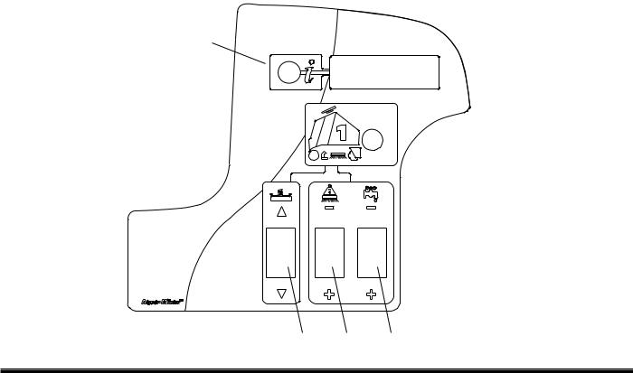
SCRUB CONTROLS-DELUXE
5
 1
1
4 3 2
1. |
One Touch Switch |
4. |
Vacuum/Squeegee Switch |
2. |
Solution Control Switch |
5. |
Display Toggle Switch |
3. |
Brush Pressure Switch |
|
|
1.ONE TOUCH SWITCH
This switch controls the scrub brushes and vacuum all in one touch.
To start scrubbing, press the one touch switch. The brush drive motors will turn on, the scrub deck will lower to the "light scrub" position, the solution will flow at “one bar” rate, the squeegee will lower and the vacuum will turn on. The information display window will show which functions are operating. If the throttle pedal is in the neutral position for more than two seconds the brushes and solution flow will stop. If the one touch switch is activated without brushes installed, the brush motors will stop, the scrub deck will rise, and the brush pressure indicator will display error code 9000.
To stop scrubbing, press the one touch switch. The brush drive motors will turn off, the scrub deck will raise the solution flow will stop, the squeegee will raise after a 15 second delay, and the vacuum motor will turn off. This delay is to clear the vacuum hose of recovered solution.
3-11 |
86037660 CHARIOT 11/09/06 |
SCRUB CONTROLS-DELUXE
2.SOLUTION CONTROL SWITCH
This switch controls the amount of solution flow to the scrub deck. The information screen will show the solution setting. There are 4 different flow settings.
To increase the solution flow, press the bottom of the solution control switch (+). To decrease solution flow, press the top of the switch (-).
If the brush motors are turned off or the throttle pedal is in neutral, the flow is automatically interrupted until the motors are turned on again, or the throttle pedal is pressed down. This feature prevents unintentional draining of the solution tank and allows the operator to adjust the solution flow to the scrub deck without resetting each time the scrubbing operation is interrupted.
3.BRUSH PRESSURE SWITCH
This switch controls the amount of brush pressure to the floor. The information display screen will show the amount of pressure. There are 4 different pressure settings.
To decrease the amount of down pressure, press the top of the brush pressure switch (-). To increase the amount of down pressure, press the bottom of the brush pressure switch (+).
4.VACUUM/SQUEEGEE SWITCH
This switch independently controls the vacuum motor and squeegee position.
To start the vacuum motor and lower the squeegee to the floor, press the bottom of the switch.
To raise the squeegee and turn off the vacuum motor, press the top of the switch. The squeegee will raise after a 15 second delay, and the vacuum motor will turn off 15 seconds later, in order to clear vacuum hose of recovered solution.
5.DISPLAY TOGGLE SWITCH
The display toggle switch allows you to change the information displayed screen. Two screens are available.
Screen 1 displays battery charge level, speed setting, brush pressure setting and solution flow setting, as well as animated scrub brush and vacuum icons when these functions are engaged.
Screen 2 displays battery charge level and hour meters. Hours are displayed for brush run time and traction motor time.
86037660 CHARIOT 11/09/06 |
3-12 |
Loading...