


USER GUIDE
G4 High Volume Combo Brewers
Dispensers not included
READ AND SAVE THESE INSTRUCTIONS
|
NOTICE TO INSTALLER: Please leave this booklet with the machine. |
|
053119D |
FC3 - G4CBHS/G4CBHT, FRONT COVER |
F-10002 revB |
CONTENTS |
CL3 |
|
|
.H\ )HDWXUHV 6SHFLÀFDWLRQV 6\VWHP 5HTXLUHPHQWV................................................................................................ |
FS3 |
,PSRUWDQW 6DIHJXDUGV............................................................................................................................................... |
IS2 |
,QVWDOODWLRQ ,QVWUXFWLRQV *HQHUDO ............................................................................................................................... |
II2 |
,QVWDOODWLRQ ,QVWUXFWLRQV /HYHOLQJ :DWHU 6XSSO\ (OHFWULFDO .................................................................................... |
II35 |
2SHUDWLQJ ,QVWUXFWLRQV .............................................................................................................................................. |
OI2 |
&OHDQLQJ ,QVWUXFWLRQV %UHZHU ................................................................................................................................. |
CI1 |
&OHDQLQJ ,QVWUXFWLRQV 7KHUPDO &RIIHH 6HUYHU ........................................................................................................ |
CI5 |
&OHDQLQJ ,QVWUXFWLRQV 7HD 'LVSHQVHU ..................................................................................................................... |
CI6 |
3URJUDPPLQJ *XLGH ............................................................................................................................................... |
3* |
5RXJK ,Q 'UDZLQJ................................................................................................................................................... |
5' |
,OOXVWUDWHG 3DUWV 5HFRPPHQGHG 3DUWV 0DLQ &KDVVLV ............................................................................................. |
IP3 |
,OOXVWUDWHG 3DUWV 5HFRPPHQGHG 3DUWV 7DQN $VVHPEO\ 6LQJOH ............................................................................ |
IP25 |
,OOXVWUDWHG 3DUWV 5HFRPPHQGHG 3DUWV 7DQN $VVHPEO\ 7ZLQ .............................................................................. |
IP26 |
(OHFWULFDO 6FKHPDWLF * &%+6 .............................................................................................................................. |
ES7 |
(OHFWULFDO 6FKHPDWLF * &%+7 .............................................................................................................................. |
ES8 |
7URXEOHVKRRWLQJ *XLGH............................................................................................................................................ |
7* |
7URXEOHVKRRWLQJ *XLGH............................................................................................................................................ |
7* |
7URXEOHVKRRWLQJ *XLGH.......................................................................................................................................... |
7* |
(UURU &RGHV............................................................................................................................................................. |
EC1 |
3URGXFW :DUUDQW\.................................................................................................................................................... |
3: |
Contact Information
Wilbur Curtis Co., Inc.
6913 Acco Street | Montebello, CA 90640 US
Phone: 323-837-2300 | Toll Free: 800-421-6150
Email: csrassistance@wilburcurtis.com | Web: www.wilburcurtis.com
'PS UIF MBUFTU TQFDJmDBUJPOT BOE JOGPSNBUJPO HP UP XXX XJMCVSDVSUJT DPN 5PMM 'SFF ] .POEBZ 'SJEBZ A.M. - 4:00 P.M. PT Email: techsupport@wilburcurtis.com
%VF UP DPOUJOVFE QSPEVDU JNQSPWFNFOU UIF QSPEVDUT JMMVTUSBUFE QIPUPHSBQIFE JO UIJT HVJEF NBZ WBSZ TMJHIUMZ GSPN UIF BDUVBM QSPEVDU
( $#)4 ( $#)5 $0/5&/54 -*45 ø |
122717A |
KEY FEATURES/SPECIFICATIONS/SYSTEM REQUIREMENTS |
FS3 |
|
|
Key Features
•Multiple Beverage Options – Allows you to brew Coffee, Iced Coffee and Iced Tea from one model.
•Generation Four (G4) Digital Control Module – Large, 4.3” touchscreen. Icon-driven interface streamlines operation. Provides precise control of all critical brewing functions.
•On-Screen Instructions – Provides fast, intuitive training; reduces service calls.
•Built-in Self Diagnostic System – Includes real-time feedback of the brewing process and energy saving mode.
•Industry’s most effective mineral tolerant design.
•Encapsulated control boards – Protect against steam, water and impact.
6SHFLÀFDWLRQV 6HOHFWHG 0RGHOV
(OHFWULFDO 6XSSO\ 5HTXLUHPHQWV
02'(/ |
'(6&5,37,21 |
3+$6( |
92/76 |
$036 |
+($7,1* &21),* |
:,5( |
:$776 |
+(57= |
*$/ +5 |
* &%+6 |
Single, Combo High Volume Brewer |
1 PH |
120/220 V |
15.0/12.7 A |
2 X 1600 W |
2W/3W + G |
1800/2800 W |
50/60 Hz |
12.0 |
* &%+7 |
Twin, Combo High Volume Brewer |
1 PH |
220 V |
23.0/34.0 A |
3 X 2500 W |
3W + G |
5100/7500 W |
50/60 Hz |
21.0 |
'LPHQVLRQV |
|
|
|
|
|
:DWHU 6XSSO\ 5HTXLUHPHQWV |
|
||
02'(/ |
|
+(,*+7 |
:,'7+ |
'(37+ |
6+,3 :(,*+7 |
6+,3 &8%( |
:$7(5 &211(&725 |
:$7(5 35(6685( |
0,1 )/2: 5$7( |
* &%+6 |
|
36.71” |
10.07” |
22.82” |
47.0 lbs |
9.27 cu ft |
µ ÁDUH |
20 - 90 psi |
1.0 gpm |
* &%+7 |
|
36.71” |
18.11” |
22.82” |
76.0 lbs |
16.04 cu ft |
µ ÁDUH |
20 - 90 psi |
2.0 gpm |
Following are the factory default settings for the combination brewer:
• Brew Temperature = 200°F |
• Brew Volume (coffee) = Large-Medium-Small |
||
• |
Minimum Brew Temperature = 195°F |
• |
Brew Volume (tea) = Large-Small |
• |
Water Bypass (coffee) = On LARGE and MEDIUM |
• |
Energy Save Mode = Off |
|
brew only |
|
|
G4CBHS/G4CBHT, KEY FEATURES/SPECS/SYSTEM REQUIREMENTS |
091316B |

IMPORTANT SAFEGUARDS |
IS2 |
|
|
Symbols
This is the safety alert symbol. It is used to alert you to potential physical injury hazards. Obey all safety messages that follow this symbol to avoid possible injury or death.
DANGER - Indicates a hazardous situation which, if not avoided, will result in death or serious injury.
WARNING - Indicates a hazardous situation which, if not avoided, could result in death or serious injury.
CAUTION - Indicates a hazardous situation which, if not avoided, could result in minor or moderate injury.
NOTICE - Indicates a situation which, if not avoided, could result in property damage.
IMPORTANT - Provides information and tips for proper operation.
SANITATION REQUIREMENTS
WARNING - 5IJT QSPEVDU DBO FYQPTF ZPV UP DIFNJDBMT JODMVEJOH "DSZMBNJEF BOE #JTQIFOPM " #1" which are known to the State of California to cause cancer and birth defects or other reproductive harm.
'PS NPSF JOGPSNBUJPO WJTJU XXX 1 8BSOJOHT DB HPW
Important Safeguards/Conventions
WARNING:
•Make sure that this appliance is installed and grounded according to the INSTALLATION
*/4536$5*0/4 CZ RVBMJmFE QFSTPOOFM CFGPSF BUUFNQUJOH UP VTF JU 'BJMVSF UP GPMMPX UIF */45"--"5*0/
INSTRUCTIONS could result in personal injury or void the warranty.
•This appliance is designed for commercial use. Any service other than cleaning and preventive maintenance should be performed by an authorized Wilbur Curtis service technician.
•5P SFEVDF UIF SJTL PG mSF PS FMFDUSJD TIPDL %0 /05 PQFO UIF TFSWJDF QBOFMT 5IFSF BSF OP VTFS serviceable parts inside.
•Keep hands, arms and other items away from hot surfaces of the unit during operation.
•Clean the appliance and any dispensers completely CFGPSF VTJOH UIFN GPS UIF mSTU UJNF BDDPSEJOH UP the CLEANING INSTRUCTIONS. Clean them regularly as instructed in the CLEANING INSTRUCTIONS.
•Use this appliance only for its intended use, brewing/dispensing hot and/or cold beverages/water.
•This appliance is not intended for use by persons (including children) with reduced physical, sensory or mental capabilities or lack of experience and knowledge, unless they have been given supervision or instruction concerning use of the appliance by a person responsible for their safety. Children should be supervised to ensure that they do not play with the appliance.
•Avoid spillage onto the power (mains) connector.
$0''&& 5&" #3&8&34 *.1035"/5 4"'&(6"3%4 4:.#0-4 |
( |
IMPORTANT SAFEGUARDS |
IS2 |
|
|
CE Requirements
•This appliance must be installed in locations where it can be overseen by trained personnel.
•'PS QSPQFS PQFSBUJPO UIJT BQQMJBODF NVTU CF JOTUBMMFE XIFSF UIF UFNQFSBUVSF JT CFUXFFO ¡$ UP ¡$
•"QQMJBODF TIBMM OPU CF UJMUFE NPSF UIBO ¡ GPS TBGF PQFSBUJPO
•"O FMFDUSJDJBO NVTU QSPWJEF FMFDUSJDBM TFSWJDF BT TQFDJmFE JO DPOGPSNBODF XJUI BMM MPDBM BOE OBUJPOBM DPEFT 'PS TBGF VTF BO BMM QPMF EJTDPOOFDUJPO NVTU CF JODPSQPSBUFE JOUP UIF mYFE XJSJOH JO BDDPSEBODF XJUI UIF XJSJOH SVMFT PVUMJOFE JO DMBVTF PG *&$ GPS NFFUJOH UIF NJOJNVN FMFDUSJDBM TBGFUZ PG UIJT TUBOEBSE
•This appliance must not be cleaned by water jet.
•5IJT BQQMJBODF DBO CF VTFE CZ QFSTPOT BHFE GSPN ZFBST BOE BCPWF JG UIFZ IBWF CFFO HJWFO TVQFSWJTJPO PS instruction concerning use of the appliance in a safe way and if they understand the hazards involved.
•,FFQ UIF BQQMJBODF BOE JUT DPSE PVU PG SFBDI PG DIJMESFO BHFE MFTT UIBO ZFBST
•"QQMJBODFT DBO CF VTFE CZ QFSTPOT ZFBST BOE BCPWF XJUI SFEVDFE QIZTJDBM TFOTPSZ PS NFOUBM DBQBCJMJUJFT or lack of experience and knowledge if they have been given supervision or instruction concerning use of the appliance in a safe way and understand the hazards involved.
•$IJMESFO VOEFS UIF BHF PG ZFBST TIPVME CF TVQFSWJTFE UP FOTVSF UIFZ EP OPU QMBZ XJUI UIF BQQMJBODF
•If the power cord is ever damaged, it must be replaced by the manufacturer or authorized service personnel with a special cord available from the manufacturer or its authorized service personnel in order to avoid a hazard.
•Machine must not be immersed for cleaning.
•$MFBOJOH BOE VTFS NBJOUFOBODF TIBMM OPU CF NBEF CZ DIJMESFO VOMFTT UIFZ BSF PMEFS UIBO ZFBST BOE supervised.
•This appliance is intended to be used in household and similar applications such as:
o TUBGG LJUDIFO BSFBT JO TIPQT PGmDFT BOE PUIFS XPSLJOH FOWJSPONFOUT
o CZ DMJFOUT JO IPUFMT NPUFMT BOE PUIFS SFTJEFOUJBM UZQF FOWJSPONFOUT
–bed and breakfast type environments.
•This appliance not intended to be used in applications such as:
–farm houses
•Access to the service areas permitted by Authorized Service personnel only.
•5IF " 8FJHIUFE TPVOE QSFTTVSF MFWFM JT CFMPX E#"
$0''&& 5&" #3&8&34 *.1035"/5 4"'&(6"3%4 4:.#0-4 |
( |

INSTALLATION INSTRUCTIONS |
II2 |
|
|
WARNING: *OTUBMMBUJPO JT UP CF QFSGPSNFE POMZ CZ B RVBMJmFE JOTUBMMFS
WARNING: *NQSPQFS FMFDUSJDBM DPOOFDUJPO NBZ SFTVMU JO BO FMFDUSJD TIPDL IB[BSE 5IJT CSFXFS NVTU CF properly grounded.
NOTICE: %0 /05 DPOOFDU UIJT CSFXFS UP B IPU XBUFS TVQQMZ 5IF XBUFS JOMFU WBMWF JT OPU SBUFE GPS IPU XBUFS %P OPU FYDFFE UIF NBYJNVN XBUFS QSFTTVSF TUBUFE JO UIF SPECIFICATIONS section.
IMPORTANT: 0CTFSWF BMM HPWFSOJOH DPEFT BOE PSEJOBODFT
Installation Instructions
Installation Requirements
•A secure surface capable of supporting the weight of the appliance.
•For units without an attached cord set: Appropriately sized, UL listed, grounding type power cable to meet
UIF FMFDUSJDBM TQFDJmDBUJPOT GPS UIF BQQMJBODF *G ZPV IBWF RVFTUJPOT BCPVU UIF DPSSFDU DBCMF TJ[F BOE MFOHUI DPOTVMU B RVBMJmFE JOTUBMMFS *G UIF BQQMJBODF XJMM CF IBSE XJSFE UP B KVODUJPO CPY UIF QPXFS DBCMF NVTU CF MPOH enough TP UIBU UIF VOJU DBO CF NPWFE GPS DMFBOJOH VOEFSOFBUI
•" HSPVOEFE FMFDUSJDBM DPOOFDUJPO UP BO FMFDUSJDBM DJSDVJU UIBU NFFUT UIF FMFDUSJDBM TQFDJmDBUJPOT PG UIF appliance (see SPECIFICATIONS 5IF DJSDVJU NVTU CF QSPUFDUFE CZ UIF BQQSPQSJBUF TJ[FE DJSDVJU CSFBLFS *G ZPV BSF OPU DFSUBJO UIBU UIF FYJTUJOH DJSDVJU NFFUT UIF SFRVJSFNFOUT GPS ZPVS VOJU DPOTVMU B MJDFOTFE FMFDUSJDJBO
•" XBUFS mMUSBUJPO TZTUFN JT SFRVJSFE UP NBJOUBJO USPVCMF GSFF PQFSBUJPO 8JMCVS $VSUJT $P *OD SFDPNNFOET B 8JMCVS $VSUJT BQQSPWFE XBUFS mMUFS 4FF UIF $VSUJT &RVJQNFOU $BUBMPH GPS B GVMM MJOF PG 8JMCVS $VSUJT BQQSPWFE XBUFS mMUFST
•1PUBCMF XBUFS TVQQMZ MJOF DPOOFDUJPO GSPN UIF XBUFS mMUFS DBQBCMF PG TVQQMZJOH UIF NJOJNVN nPX SBUF SFRVJSFE
CZ UIF TQFDJmDBUJPOT 5IF XBUFS TVQQMZ MJOF NVTU CF BCMF UP DPOOFDU UP UIF nBSF mUUJOH PO UIF CBDL PG UIF VOJU 4FF UIF SPECIFICATIONS section for the correct size. The water line should also be capable of being
DPOUSPMMFE CZ B TIVU PGG WBMWF %P OPU DPOOFDU UIF XBUFS MJOF UP B TBEEMF WBMWF PS OFFEMF WBMWF
 /4' *OUFSOBUJPOBM SFRVJSFT UIF GPMMPXJOH XBUFS DPOOFDUJPO
1 " RVJDLEJTDPOOFDUPSBEEJUJPOBMDPJMFEUVCJOH BUMFBTUUXPUJNFTUIFEFQUIPGUIFappliance JTSFRVJSFE
TP UIBU JU DBO CF NPWFE GPS DMFBOJOH VOEFSOFBUI
2 5IJT FRVJQNFOU JT UP CF JOTUBMMFE XJUI BEFRVBUF CBDL nPX QSPUFDUJPO UP DPNQMZ XJUI BQQMJDBCMF federal, state and local codes.
8BUFS QJQF DPOOFDUJPOT BOE mYUVSFT EJSFDUMZ DPOOFDUFE UP B QPUBCMF XBUFS TVQQMZ TIBMM CF TJ[FE installed and maintained in accordance with federal, state and local codes.
5IF *OUFSOBUJPOBM 1MVNCJOH $PEF PG UIF *OUFSOBUJPOBM $PEF $PVODJM BOE UIF 'PPE BOE %SVH "ENJOJTUSBUJPO '%" 'PPE $PEF NBOVBM EJSFDU UIBU UIJT FRVJQNFOU NVTU CF JOTUBMMFE XJUI BEFRVBUF CBDL nPX QSFWFOUJPO JO DPNQMJBODF XJUI GFEFSBM TUBUF BOE MPDBM DPEFT 'PS VOJUT JOTUBMMFE PVUTJEF PG UIF 6 4 " NBLF TVSF UIBU the installation is in compliance with the applicable plumbing/sanitation code for your area.
#3&8&34 (&/&3*$ */45"--"5*0/ */4536$5*0/4 |
% |
INSTALLATION INSTRUCTIONS
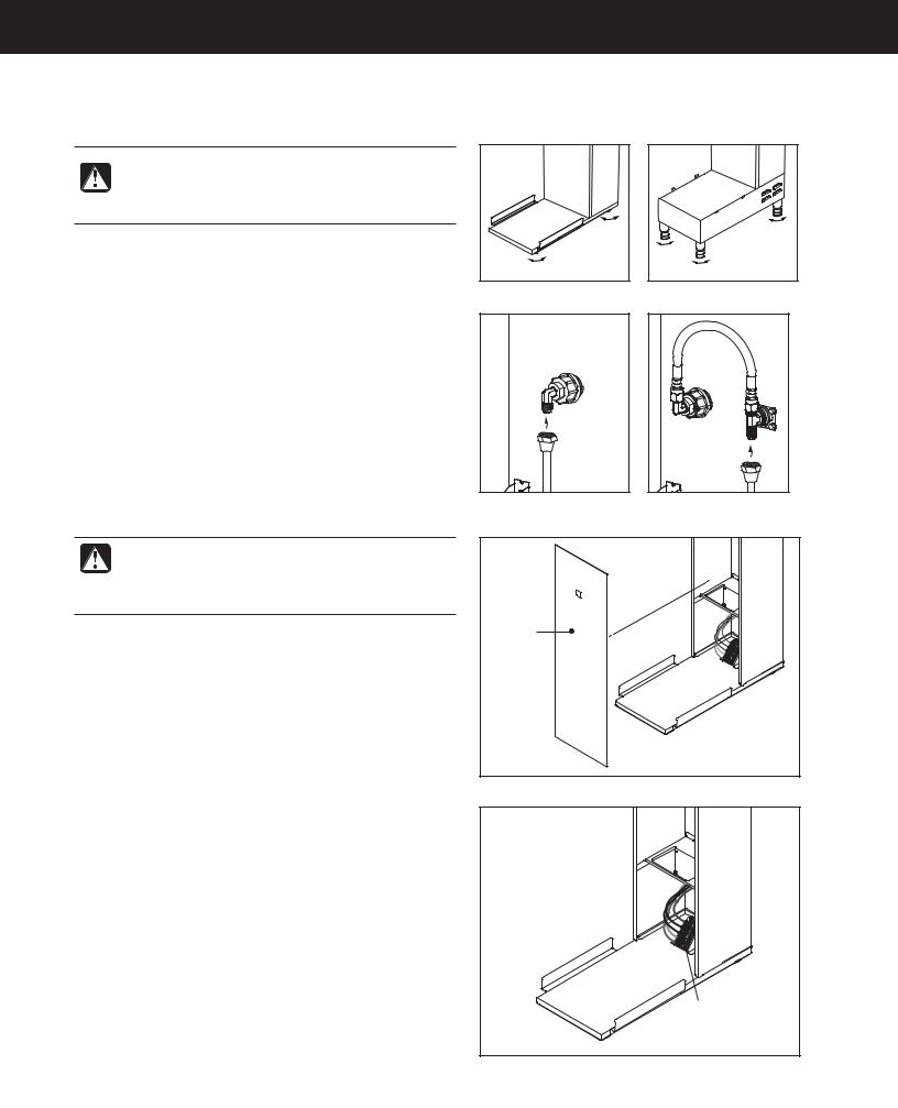
Installation
Leveling
WARNING: Use the leveling legs to level the brewer only. Do not use them to adjust brewer height. Do not extend them higher than necessary.
1Position the brewer on the counter top. Level it left to right and front to back by turning the bottom of the legs.
Connect the Water Supply
2Flush the water supply line prior to installation to
QVSHF BJS BOE EFCSJT GSPN UIF XBUFS mMUFS BOE UVCJOH
3$POOFDU UIF XBUFS TVQQMZ MJOF UP UIF nBSF mUUJOH PO the back of the brewer. Leave the water supply valve closed until the power is connected.
Connect the Brewer Wiring
Brewers Without A Cord Set Attached
WARNING: Turn off power to the junction box at the circuit breaker panel before connecting the power cable to the brewer. Lock out and tag the circuit breaker.
4Remove the screws that hold the front cover in place and remove the cover.
5Loosen the strain relief on the back of the brewer.
6On dual voltage units being operated at 220 Volts (nominal) disconnect the existing power cable from the terminal block and remove.
7Feed the 220 Volt power cable into the brewer.
8On dual voltage units being operated at 220 Volts, disconnect and cap the jumper wire between the “C” and “N” terminals on the terminal block.
9Connect the wires on the power cable to the terminal block inside the brewer.
10Tighten the strain relief and replace the front cover.
11Connect the power cable wires to the terminals in the junction box. See the ELECTRICAL SCHEMATIC for the power supply requirements.
II35
Front panel
Terminal
block
DECANTER/DISPENSER BREWERS, INSTALLATION INSTRUCTIONS - 200F |
112917NC |

INSTALLATION INSTRUCTIONS |
II35 |
|
|
Connect the Brewer Wiring (cont.)
Brewers With A Cord Set Attached
12 On export models with a power cord already installed, install the appropriate type of power plug for your locality. Consult local electrical codes to determine the approved type of power plug for your region.
13Connect the power plug to the appropriate electrical outlet.
WARNING: Connect the power plug to the appropriate type and size electrical outlet. If the electrical outlet is not compatible with the power plug, have it upgraded by a licensed electrician. Do not modify the power plug. Do not use an extension cord. Do not use a power cord/plug that is damaged.
Connect the Bag-in-Box (BIB) Sweetener -
Units Equipped for Brewing Sweet Tea Only
14 Connect two Bag-in-Box (BIB) sweeteners to the brewer sweetener supply hoses as instructed in the
OPERATING INSTRUCTIONS section. Connecting two bags allows the brewer to continue operating if one bag runs out.
Power Up the Brewer
15 Turn on the water supply valve.
16Make sure that the circuit breaker supplying power to the unit is on.
17Turn the toggle switch on the back of the brewer to the
0/ QPTJUJPO 5IF XBUFS UBOL XJMM TUBSU UP mMM 8IJMF UIF UBOL JT mMMJOH JOTQFDU UIF XBUFS TVQQMZ MJOF GPS MFBLT
IMPORTANT: When operating the brewer at higher elevations, reduce the factory set operating temperature (200°F) by 2°F for each 1000 feet of elevation above 4000 feet. See PROGRAMMING GUIDE.
continued...
DECANTER/DISPENSER BREWERS, INSTALLATION INSTRUCTIONS - 200F |
112917NC |
INSTALLATION INSTRUCTIONS |
II35 |
|
|
18When the water in the tank rises to the correct level, the heating elements will turn on automatically. Depending on the incoming water temperature and the electrical
TQFDJmDBUJPOT UIF XBUFS UBOL UZQJDBMMZ SFRVJSFT UP
minutes to reach the factory set operating temperature. When the water has heated, Ready to brew will be displayed on the LCD screen.
19Perform a brew cycle of a least 12 ounces to purge any remaining air from the system. See OPERATING INSTRUCTIONS. During the initial brew cycle and
XIFOFWFS UIF mMUFS JT SFQMBDFE ZPV NBZ IFBS UIF TPVOET PG BJS CFJOH QVSHFE GSPN UIF mMUFS UVCJOH BOE water tank.
DECANTER/DISPENSER BREWERS, INSTALLATION INSTRUCTIONS - 200F |
112917NC |

OPERATING INSTRUCTIONS |
OI2 |
|
|
Brewing Instructions
WARNING - TO AVOID SCALDING, AVOID SPLASHING. Keep body parts clear of the brewer during brewing. Do not remove the brew basket while “Brewing” appears on the display.
WARNING - DO NOT refrigerate unused tea overnight for later consumption.
The G4 Combo Brewer is factory preset for optimal performance.
The brewer should be ON. $POmSN UIJT BU UIF SFBS UPHHMF switch. “Ready to brew” should be on the display.
2Remove the lid from an empty coffee or tea
dispenser and position it on the brew deck. Center it under the brew basket.
3Select the brew basket labeled for the type of beverage being brewed (hot coffee, iced coffee or iced tea)
BOE JOTFSU B DMFBO QBQFS mMUFS
Fill with the proper amount of coffee or leaf tea. Level the
DPGGFF UFB JO UIF mMUFS
|
|
|
|
|
|
|
|
|
|
|
|
|
|
|
|
|
|
|
|
|
|
|
|
|
|
|
|
|
|
|
|
|
|
|
|
|
|
|
|
|
|
|
|
|
|
|
|
|
|
|
|
|
|
|
|
|
|
|
|
|
|
|
|
|
|
|
|
|
|
|
|
|
|
|
|
|
|
|
|
|
|
|
|
|
|
|
|
|
|
|
|
|
|
|
|
|
|
|
|
|
|
|
|
|
|
|
|
|
|
|
|
|
|
|
|
|
|
|
|
|
|
|
|
|
|
|
|
|
|
|
|
|
|
|
|
|
|
|
|
|
|
|
|
|
|
|
|
|
|
|
|
|
|
|
|
|
|
|
|
|
|
|
|
|
|
|
|
|
|
|
|
|
|
|
|
|
|
|
|
|
|
|
|
|
|
|
|
|
|
|
|
|
|
|
|
|
|
|
|
|
|
|
|
|
|
|
|
|
|
|
|
|
|
|
|
|
|
|
|
|
|
|
|
|
|
|
|
|
|
|
|
|
|
|
|
|
|
|
|
|
|
|
|
|
|
|
|
|
|
|
|
|
|
|
|
|
|
|
|
|
|
|
|
|
|
|
|
|
|
|
|
|
|
|
|
|
|
|
|
|
|
|
|
|
|
|
|
|
|
|
|
|
|
|
|
|
|
|
|
|
|
|
|
|
|
|
|
|
|
|
|
|
|
|
|
|
|
|
|
|
|
|
|
|
|
|
|
|
|
|
|
|
|
|
|
|
|
|
|
|
|
|
|
|
|
|
|
|
|
|
|
|
|
|
|
|
|
|
|
4 4MJEF UIF mMMFE CSFX CBTLFU |
)PME ZPVS mOHFS PO UIF |
6 If a keypad appears on |
|||||||||||||||||
into the brew rails under the |
appropriate brew icon. As |
|
the display, the brew code |
||||||||||||||||
control panel. Slide it all the |
soon as you hear the click |
|
feature is enabled (default |
||||||||||||||||
way back until it stops. |
of the brew valve, lift your |
|
is off). Brewing will start |
||||||||||||||||
|
|
|
|
|
mOHFS #SFXJOH XJMM CFHJO |
|
immediately after you enter |
||||||||||||
|
|
|
|
|
|
|
|
|
|
|
|
|
|
|
the brew code. See the |
||||
|
|
|
|
|
|
|
|
|
|
|
|
|
|
|
PROGRAMMING GUIDE to |
||||
|
|
|
|
|
|
|
|
|
|
|
|
|
|
|
set up/disable the brew code. |
||||
The brewer will brew coffee or tea based on the settings programmed into the universal control module (UCM). To change the settings, see the PROGRAMMING GUIDE.
( $#)4 ( $#)5 01&3"5*/( */4536$5*0/4 ø |
" |
|
CLEANING INSTRUCTIONS |
CI1 |
|
|
|
|
|
|
|
|
|
WARNING: HOT SURFACES - To avoid injury, allow the brewer and dispenser(s) to cool before cleaning.
NOTICE - Do not use cleaning liquids, compounds or powders containing chlorine (bleach) or corrosives.
5IFTF QSPEVDUT QSPNPUF DPSSPTJPO BOE XJMM EBNBHF UIF mOJTIFT USE OF THESE PRODUCTS WILL VOID
THE WARRANTY.
Cleaning The Brewer - Daily
WARNING: DO NOT immerse the brewer in water or any other liquid.
The brewer should be OFF. 5VSO UIF CSFXFS PGG CZ nJQQJOH UIF SFBS UPHHMF TXJUDI UP UIF 0'' QPTJUJPO
1Remove the dispenser(s). Wipe exterior brewer surfaces with a damp cloth to remove spills and debris.
2Remove the brew basket(s) and clean them in a mild detergent solution. Use a soft bristled brush for hard to clean areas. Rinse with clean water, then dry.
3Wipe the spray head area with a cloth soaked in a mild detergent solution. Rinse with a cloth soaked with clean water removing any residual detergent. Use a clean, soft cloth to dry.
4Dump out the drip tray(s) (if applicable). Rinse with clean water, then dry with a soft, clean cloth.
Cleaning The Brewer - Weekly
The brewer should be OFF. 5VSO UIF CSFXFS PGG CZ nJQQJOH UIF SFBS UPHHMF TXJUDI UP UIF 0'' QPTJUJPO
1Remove the spray head(s), unscrewing counterclockwise from the dome plate.
2Thoroughly clean and rinse the dome plate area.
3Clean the brew basket rails with a brush soaked with a mild detergent solution. Rinse the area with a cloth soaked with clean water, removing any residual detergent.
4Dry the area with a soft, clean cloth.
5Reattach the spray head(s).
BREWERS - GENERIC, CLEANING INSTRUCTIONS |
080416B |
 Loading...