


White Rodgers Acb1000, Acb1400, Acb1600, Acb2000, Acm1400 Owner's Manual
...
Air Filter Compartment
Model Number
ACM/ACB
With Media Filter ACM1000 ACM1200TM ACM1400 ACM1600 ACM2000 ACM2000U ACM2000X
No Media Filter
ACB1000
ACB1400
ACB1600
ACB2000
OWNER’S MANUAL
•Installation
•Operation
•Technical Repair Guide
•Repair and Upgrade Parts
Please read and familiarize yourself with the contents of this manual before installing, operating or performing maintenance on the unit.
White-Rodgers is a division |
PART NO. 37-6383C |
|
of Emerson Electric Co. |
||
Replaces 37-6383B |
||
www.white-rodgers.com |
||
0446 |
INTRODUCTION
The White-Rodgers Air Cleaner Compartment comes complete with a 5” media furnace air filter. This filter must be changed every three months to maintain efficiency of the filter and furnace system. For maximum efficiency, the compartment can be upgraded to a White-Rodgers Electronic Air Cleaner.
Please read instructions before installing and using the Air Filter Compartment.
▲! CAUTION
The fiber filter used in this cabinet for air cleaning must be replaced every 90 days. Your heating and cooling efficiency will decrease due to insufficient air flow when filter becomes dirty.
▲! WARNING
Do not attempt installation of this unit unless you are familiar with the necessary tools, equipment, and potential hazards.
Installation should be performed only by a qualified service provider.
Failure to do so could result in reduced performance of the unit, serious personal injury or death.
GUARANTEE
White-Rodgers will not assume any responsibility for component failures due to incorrect installation procedures.
RULES FOR SAFE INSTALLATION
AND OPERATION
1.Read the Owners Manual and the Rules for Safe Operation carefully. Failure to follow these rules and instructions could cause a malfunction of filter or unsatisfactory service.
▲! WARNING
Installation of this unit must comply with local electric codes or other applicable codes.
Review and understand local codes prior to installation.
▲! WARNING
Before installing or servicing, always shut off electricity. This will prevent any electrical shocks.
2.Follow a regular service and maintenance schedule for efficient operation.
TABLE OF CONTENTS |
|
Rules for Safe Installation and Operation ............ |
2 |
How the Air Filter Works ...................................... |
3 |
Construction of the Air Filter Compartment ......... |
3 |
Preinstallation ....................................................... |
4 |
Installation ............................................................ |
6 |
Maintenance ......................................................... |
7 |
Repair and Upgrade Parts ................................... |
7 |
BASIC TOOLS REQUIRED
Tin Snip
Screwdriver
Rule or Tape Measure
Drill
DID YOU GET THE RIGHT SIZE
AIR FILTER COMPARTMENT
Model ACB & ACM1000 are designed for heating or cooling blowers delivering 600 to 1200 cubic feet of air per minute (cfm.)
Model ACM1200TM is designed for heating or cooling blowers delivering 1000 to 1600 cfm.
Model ACB & ACM1400 are designed for heating or cooling blowers delivering 1000 to 1600 cfm.
Model ACB & ACM1600 are designed for heating or cooling blowers delivering 1200 to 1800 cfm.
Model ACB, ACM2000 & ACM2000X are designed for heating or cooling blowers delivering 1600 to 2200 cfm.
Model ACM2000U is designed for heating or cooling blowers delivering 1600 to 2200 cfm. with insulation on door and universal rail.
Before installing the filter, make sure you have selected the proper size unit for your heating and cooling system requirements. See specifications on page 4.
2
|
|
|
5" FILTER |
||
HOW THE AIR FILTER WORKS |
|
|
|
|
|
|
|
|
|
|
|
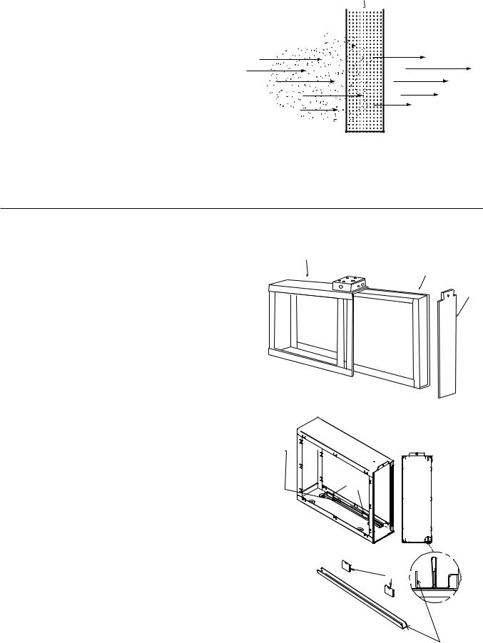
Dirty air flows through your return air ducts and enters the |
DIRTY AIR IN |
|
|
FILTERED AIR OUT |
|
compartment where particles (hair, lint, etc.) are removed |
|
|
|||
|
|
|
|
|
|
by the filter. See figure 1. |
|
|
|
|
|
|
|
|
|
|
|
Filtered air re-enters to the supply duct system of your building.
Figure 1
CONSTRUCTION OF THE AIR FILTER COMPARTMENT
Not only is your air filter compartment easy to install, it is also easy to maintain. Its basic components, and their functions, are as follows: (See Figure 2)
Air Filter Compartment- mounts to existing duct work and houses the filters or optional electronic air cleaner cells.
NOTE: To upgrade your air filter compartment with a high efficiency Electronic Air Cleaner, use the ACR (Air Cleaner Retrofit) Kit for your model. See page 7 for details.
5” Filter - collects dust, dirt and other particles.
Note ACM2000U Compartment: This unit has removable rails (see figure 2A). This unit is installed with the rails to be used with a 24.5” x 19.9” x 4.3” filter. Remove the rails and a 5” filter may be used.
AIR FILTER COMPARTMENT
Figure 2
IF RAILS AND CLIPS ARE
REQUIRED, CLIP RAILS
IN PLACE BEFORE
INSERTING FILTER
RAIL |
AND |
|
|
CLIPS |
|
|
|
5" FILTER
DOOR
 FRONT
FRONT
VIEW
CLIPS
Figure 2A
RAIL
3
PREINSTALLATION
LOCATING THE AIR FILTER
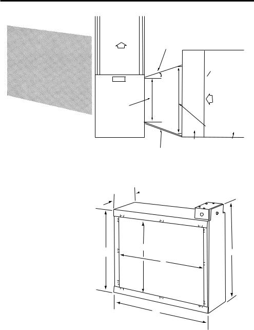
Your air filter must be mounted in the return air duct of a central forced-air system, on the air entering side of your furnace. (See Figure 3 for example.)
Select a location that meets the following:
1.The face of the filter will be at a right angle to the air stream.
2.Allow 25” of clearance in front of the air filter compartment door to permit removal of filters.
See figure 4 for complete compartment dimensions.
3.The air filter is not to be placed in the discharge of either the heating or cooling unit.
4.IMPORTANT: If atomizing spray type humidifier is used, it must be installed downstream from the air filter.
If furnace opening cannot be enlarged to required size, a transition sheet metal section must be used. Transition must be planned for each job. Reduction should not be more than 4 inches per linear foot, approximately 20 angular degrees (Figure 3).
NOT TO EXCEED 20
AIR FLOW
THIS CABINET
CAN ACCEPT
ELECTRONIC AIR CLEANER
OPTION
 (SEE PAGE 7)
AIR FLOW
FURNACE
OPENING
AIR CLEANER
OPENING
FURNACE |
AIR CLEANER |
DUCTWORK |
TRANSITION SECTION (IF NEEDED)
Figure 3
 F
F
C
D |
E |
B
A
Figure 4
Model No. |
A |
B |
C |
D |
E |
F |
ACB/ACM1000 |
20-1/4 |
12-5/8 |
13-9/16 |
16-7/16 |
19-1/16 |
6-7/8 |
|
|
|
|
|
|
|
ACB/ACM1400 |
26-1/4 |
23-5/8 |
13-9/16 |
16-7/16 |
19-1/16 |
6-7/8 |
|
|
|
|
|
|
|
ACB/ACM1600 |
20-1/4 |
12-5/8 |
17-3/4 |
20-5/8 |
23-3/8 |
6-7/8 |
|
|
|
|
|
|
|
ACB/ACM2000 |
26-1/4 |
23-5/8 |
17-3/4 |
20-5/8 |
23-3/8 |
6-7/8 |
|
|
|
|
|
|
|
ACM1200TM |
24-5/8 |
21-29/32 |
13-1/2 |
16-15/32 |
12-13/32 |
4-15/16 |
|
|
|
|
|
|
|
ACM2000U |
24-5/16 |
22-5/16 |
17-3/16 |
20-3/16 |
21-5/32 |
6-7/8 |
|
|
|
|
|
|
|
ACM2000X |
24-5/16 |
22-5/16 |
17-3/16 |
20-3/16 |
21-5/32 |
6-7/8 |
|
|
|
|
|
|
|
4
TYPICAL MOUNTING POSITIONS
AIR FLOW |
AIR FLOW |
|
Figure 5
Figure 6
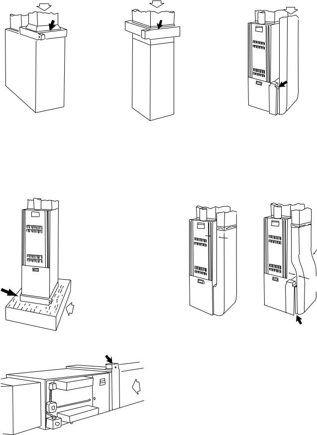
BASEMENT FURNACE (LOWBOY) (Figure 5)
Filter is mounted horizontally in return plenum, just above furnace.
COUNTERFLOW
FURNACE (Figure 6)
Filter is mounted horizontally in return duct or plenum, just above furnace.
HIGHBOY FURNACE (Figure 8)
Installation beneath furnace. Filter mounts horizontally, where return air enters from below. Raise furnace and install beneath base.
AIR FLOW
AIR FLOW
Figure 7
HIGHBOY FURNACE (Figure 7)
Side installation. Filter is mounted vertically, where return air enters side inlet of furnace.
LESS THAN |
|
7 INCHES |
OFFSET |
AT LEAST 9 INCHES
FIGURE 9
AIR |
FLOW |
|
OFFSET INSTALLATION (Figure 9)
Typical use of duct offset to match air filter opening.
If duct connection to furnace allows less than nine inches for mounting the air filter, shorten the lateral trunk, or attach an offset fitting to the elbow.
|
HORIZONTAL FURNACE |
|
|
(Figure 10) |
|
Figure 10 |
Filter is mounted vertically in |
|
the return duct near furnace. |
||
|
5
 Loading...