


OPERATOR’S MANUAL
Models
Z - 180
Z - 180L
Z - 200
IMPORTANT: READ SAFETY RULES AND INSTRUCTIONS CAREFULLY
Warning: This unit is equipped with an internal combustion engine and should not be used on or near any unimproved forestcovered, brush-covered or grass-covered land unless the engine’s exhaust system is equipped with a spark arrester meeting applicable local or state laws (if any). If a spark arrester is used, it should be maintained in effective working order by the operator. In the State of California the above is required by law (Section 4442 of the California Public Resources Code). Other states may have similar laws. Federal laws apply on federal lands. A spark arrester for the muffler is available through your nearest engine authorized service dealer or contact the service department, P.O. Box 361131 Cleveland, Ohio 44136-9722.
WHITE OUTDOOR PRODUCTS COMPANY P.O. BOX 361131 CLEVELAND, OHIO 44136-9722
PRINTED IN U.S.A. |
FORM NO. 770-10104 |
|
(10/98) |

SECTION 1: FINDING YOUR MODEL NUMBER
This Owner’s Guide is an important part of your new Z-Series. It will help you prepare, operate and maintain your mower. Please read and understand what it says.
Before you start to prepare your mower for its first use, please locate the model plate and copy the information from it in this Owner’s Guide. The information on the model plate is very important if you need help from your dealer. See Figure 1.
•Every mower has a model plate. You can locate it by opening the engine cover and looking down at the battery stand. It is located on the rear face of the battery stand.
WHITE OUTDOOR PRODUCTS COMPANY
Copy the model number here:
P.O. BOX 361131
CLEVELAND, OHIO 44136
Copy the serial number here:
Figure 1
SECTION 2: CALLING WARRANTY SERVICE
If you are having difficulty assembling this product or if you have any question regarding the controls, operation or maintenance of this unit, please call the Customer Dealer Referral Line. You can reach them by calling:
1-800-949-4483
Before calling your local dealer, make sure that you have your model and serial numbers ready. By having the model and serial numbers ready, you help your local dealer give you faster service. To find your unit’s model and serial number, see SECTION 2: FINDING YOUR MODEL NUMBER.
2

SECTION 3: IMPORTANT SAFE OPERATION PRACTICES
WARNING: THIS SYMBOL POINTS OUT IMPORTANT SAFETY INSTRUCTIONS WHICH, IF NOT FOLLOWED, COULD ENDANGER THE PERSONAL SAFETY AND/OR PROPERTY OF YOURSELF AND OTHERS. READ AND FOLLOW ALL INSTRUCTIONS IN THIS MANUAL BEFORE ATTEMPTING TO OPERATE YOUR LAWN MOWER. FAILURE TO COMPLY WITH THESE INSTRUCTIONS MAY RESULT IN PERSONAL INJURY. WHEN YOU SEE THIS SYMBOL, HEED ITS WARNING.
DANGER: Your lawn mower was built to be operated according to the rules for safe operation in this manual. As with any type of power equipment, carelessness or error on the part of the operator can result in serious injury. This lawn mower is capable of amputating hands and feet and throwing objects. Failure to observe the following safety instructions could result in serious injury or death.
1.GENERAL OPERATION
•Read, understand, and follow all instructions in the manual and on the machine before starting. Keep this manual in a safe place for future and regular reference and for ordering replacement parts.
•Only allow responsible individuals familiar with the instructions to operate the machine. Know controls and how to stop the machine quickly.
•Do not put hands or feet under mower deck or near rotating parts.
•Clear the area of objects such as rocks, toys, wire, etc., which could be picked up and thrown by the blade. A small object may have been overlooked and could be accidentally thrown by the mower in any direction and cause injury to you or a bystander. To help avoid a thrown objects injury, keep children, bystanders and helpers at least 75 feet from the mower while it is in operation. Always wear safety glasses or safety goggles during operation or while performing an adjustment or repair, to protect eyes from foreign objects. Stop the blade(s) when crossing gravel drives, walks or roads.
•Be sure the area is clear of other people before mowing. Stop machine if anyone enters the area.
•Never carry passengers.
•Disengage blade(s) before shifting into reverse and backing up. Always look down and behind before and while backing.
•Be aware of the mower and attachment discharge direction and do not point it at anyone. Do not operate the mower without either the entire grass catcher or the chute guard in place.
•Slow down before turning. Operate the machine smoothly. Avoid erratic operation and excessive speed.
•Never leave a running machine unattended. Always turn off blade(s), place transmission in neutral, set park brake, stop engine and remove key before dismounting.
•Turn off blade(s) when not mowing.
•Stop engine and wait until blade(s) comes to a complete stop before (a) removing grass catcher or unclogging chute, or (b) making any repairs, adjusting or removing any grass or debris.
•Mow only in daylight or good artificial light.
•Do not operate the machine while under the influence of alcohol or drugs.
•Watch for traffic when operating near or crossing roadways.
•Use extra care when loading or unloading the machine into a trailer or truck. This unit should not be driven up or down a ramp onto a trailer or truck under power, because the unit could tip over, causing serious personal injury. The unit must be pushed manually on a ramp to load or unload properly.
•Never make a cutting height adjustment while engine is running if operator must dismount to do so.
•Wear sturdy, rough-soled work shoes and closefitting slacks and shirts. Do not wear loose fitting clothes or jewelry. They can be caught in moving parts. Never operate a unit in bare feet, sandals, or sneakers.
•Check overhead clearance carefully before driving under power lines, wires, bridges or low hanging tree branches, before entering or leaving buildings, or in any other situation where the operator may be struck or pulled from the unit, which could result in serious injury.
•Disengage all attachment clutches, thoroughly depress the brake pedal, and shift into neutral before attempting to start engine.
•Your mower is designed to cut normal residential grass of a height no more than 10". Do not attempt to mow through unusually tall, dry grass (e.g., pasture) or piles of dry leaves. Debris may build up on the mower deck or contact the engine exhaust presenting a potential fire hazard.
3
2.SLOPE OPERATION
•Slopes are a major factor related to loss of control and tip-over accidents which can result in severe injury or death. All slopes require extra caution. If you cannot back up the slope or if you feel uneasy on it, do not mow it.
•For your safety, use the slope gauge included as part of this manual to measure slopes before operating this unit on a sloped or hilly area. If the slope is greater than 15° as shown on the slope gauge, do not operate this unit on that area or serious injury could result.
DO:
•Mow up and down slopes, not across.
•Remove obstacles such as rocks, limbs, etc.
•Watch for holes, ruts or bumps. Uneven terrain could overturn the machine. Tall grass can hide obstacles.
•Use slow speed. Choose a low enough gear so that you will not have to stop or shift while on the slope. Always keep machine in gear when going down slopes to take advantage of engine braking action.
•Follow the manufacturer’s recommendations for wheel weights or counterweights to improve stability.
•Use extra care with grass catchers or other attachments. These can change the stability of the machine.
•Keep all movement on the slopes slow and gradual. Do not make sudden changes in speed or direction. Rapid engagement or braking could cause the front of the machine to lift and rapidly flip over backwards which could cause serious injury.
•Avoid starting or stopping on a slope. If tires lose traction, disengage the blade(s) and proceed slowly straight down the slope.
DO NOT:
•Do not turn on slopes unless necessary; then, turn slowly and gradually downhill, if possible.
•Do not mow near drop-offs, ditches or embankments.The mower could suddenly turn over if a wheel is over the edge of a cliff or ditch, or if an edge caves in.
•Do not mow on wet grass. Reduced traction could cause sliding.
•Do not try to stabilize the machine by putting your foot on the ground.
•Do not use grass catcher on steep slopes.
3.CHILDREN
Tragic accidents can occur if the operator is not alert to the presence of children. Children are often attracted to the machine and the mowing activity. Never assume that children will remain where you last saw them.
•Keep children out of the mowing area and in watchful care of an adult other than the operator.
•Be alert and turn machine off if children enter the area.
•Before and when backing, look behind and down for small children.
•Never carry children. They may fall off and be seriously injured or interfere with the safe machine operation.
•Never allow children under 14 years old to operate the machine. Children 14 years and over should only operate machine under close parental supervision and proper instruction.
•Use extra care when approaching blind corners, shrubs, trees or other objects that may obscure your vision of a child or other hazard.
•Remove key when machine is unattended to prevent unauthorized operation.
4.SERVICE
•Use extreme care in handling gasoline and other fuels. They are extremely flammable and the vapors are explosive.
•Use only an approved container.
•Never remove fuel cap or add fuel with the engine running. Allow engine to cool at least two minutes before refueling.
•Replace fuel cap securely and wipe off any spilled fuel before starting the engine as it may cause a fire or explosion.
•Extinguish all cigarettes, cigars, pipes and other sources of ignition.
•Never refuel the machine indoors because fuel vapors will accumulate in the area.
•Never store the fuel container or machine inside where there is an open flame or spark, such as a gas hot water heater, space heater or furnace.
•Never run a machine inside a closed area.
•To reduce fire hazard, keep the machine free of grass, leaves or other debris build-up. Clean up oil or fuel spillage. Allow machine to cool at least 5 minutes before storing.
•Before cleaning, repairing or inspecting, make certain the blade and all moving parts have stopped. Disconnect the spark plug wire, and keep the wire away from the spark plug to prevent accidental starting.
•Check the blade and engine mounting bolts at frequent intervals for proper tightness. Also, visually inspect blade for damage (e.g., excessive wear, bent, cracked). Replace with blade which meets original equipment specifications.
•Keep all nuts, bolts and screws tight to be sure the equipment is in safe working condition.
4

•Never tamper with safety devices. Check their proper operation regularly. Use all guards as instructed in this manual.
•After striking a foreign object, stop the engine, remove the wire from the spark plug and thoroughly inspect the mower for any damage. Repair the damage before restarting and operating the mower.
•Grass catcher components are subject to wear, damage and deterioration, which could expose moving parts or allow objects to be thrown. For your safety protection, frequently check components and replace with manufacturer’s recommended parts when necessary.
•Mower blades are sharp and can cut. Wrap the blade(s) or wear gloves and use extra caution when servicing blade(s).
•Check brake operation frequently. Adjust and service as required.
•Muffler, engine and belt guards become hot during operation and can cause a burn. Allow to cool down before touching.
•Do not change the engine governor settings or overspeed the engine. Excessive engine speeds are dangerous.
•Observe proper disposal laws and regulations. Improper disposal of fluids and materials can harm the environment and the ecology.
•Prior to disposal, determine the proper method to dispose of waste from your local Environmental Protection Agency. Recycling centers are established to properly dispose of materials in an environmentally safe fashion.
•Use proper containers when draining fluids. Do not use food or beverage containers that may mislead someone into drinking from them. Properly dispose of the containers immediately following the draining of fluids.
•DO NOT pour oil or other fluids into the ground, down a drain or into a stream, pond, lake or other body of water. Observe Environmental Protection Agency regulations when disposing of oil, fuel, coolant, brake fluid, filters, batteries, tires and other harmful waste.
WARNING - YOUR RESPONSIBILITY: Restrict the use of this power machine to persons who read, understand and follow the warnings and instructions in this manual and on the machine.
Figure 2 Safety Labels Found On Unit
WARNING: The Engine Exhaust from this product contains chemicals known to the State of California to cause cancer, birth defects or other reproductive harm.
5

USE THIS PAGE AS A GUIDE TO DETERMINE SLOPES WHERE YOU MAY NOT OPERATE SAFELY.
Slope Gauge
SIGHT AND HOLD THIS LEVEL WITH A VERTICAL TREE
A POWER POLE
A CORNER OF A BUILDING
OR A FENCE POST
F |
|
|
|
O |
|
|
|
L |
|
|
|
D |
|
|
|
O |
|
|
|
N |
|
|
|
D |
|
|
|
O |
|
|
|
T |
|
|
|
T |
|
|
|
E |
|
|
|
D |
|
|
|
L |
|
|
|
|
IN |
|
|
|
E |
|
|
|
, |
|
|
|
R |
|
|
|
E |
|
|
|
P |
|
|
|
R |
|
|
|
E |
|
|
|
S |
|
|
|
E |
|
|
|
N |
|
|
|
T |
|
|
|
IN |
|
|
|
G |
|
|
|
A |
|
|
|
1 |
|
|
|
5 |
|
|
|
|
° |
|
|
|
|
S |
|
|
|
L |
|
|
|
O |
|
|
|
P |
|
|
|
E |
6
15°
WARNING
Do not mow on inclines with a slope in excess of 15 degrees (a rise of approximately 2-1/2 feet every 10 feet). A riding mower could overturn and cause serious injury. If operating a walk-behind mower on such a slope, it is extremely difficult to maintain your footing and you could slip, resulting in serious injury.
Operate RIDING mowers up and down slopes, never across the face of slopes. Operate WALK-BEHIND mowers across the face of slopes, never up and down slopes.
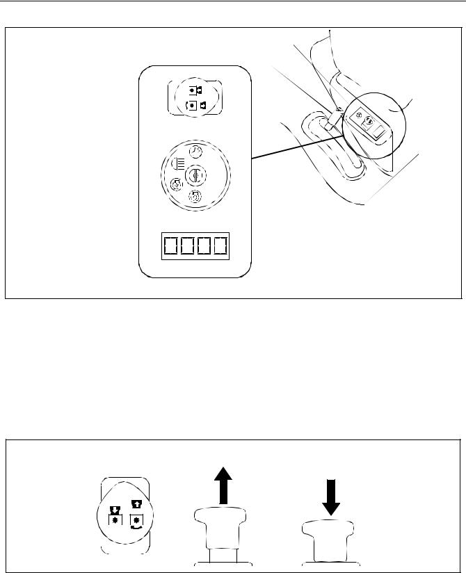
SECTION 4: CONTROLS
Right Control Panel
Lift Handle
PTO Switch
Ignition/Light Switch
Hour/RPM Meter
Front
Figure 3
HOUR/RPM METER
The hour/RPM meter is an LCD (liquid crystal display) display that is located on the Right Control Panel. The meter’s display stays on continuously. (See Figure 3)
•HOUR METER: The meter functions as an hour meter. The hour value is the number of hours of engine operation. Use the hour value to determine when maintenance is required and to cost jobs.
•RPM METER: When the engine is on, the meter functions as an engine RPM gauge.
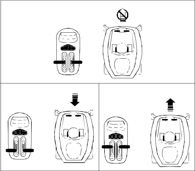
POWER TAKE-OFF (PTO) SWITCH
Top View |
Pull Up |
Push Down |
|
ON
OFF
Figure 4
The PTO switch is located on the Right Control Panel. (See Figure 4) It controls the engagement of the cutting blades. When the switch is:
•UP: The cutting blades are engaged (blades are turning).
•DOWN: The cutting blades are disengaged (not turning).
7
IGNITION/LIGHT SWITCH
 Off
Off
 On/Light
 On
On
 Start
Start
Figure 5
The ignition/light switch is located on the Right Control Panel and is used to start the engine. It is a four position switch.
•In the OFF position the engine is not running. (See Figure 5)
•In the ON/LlGHT position the engine is running and the Head Light is on.
•In the ON position the engine is running and the head light is off.
•In the START position the starter is engaged to the engine flywheel.
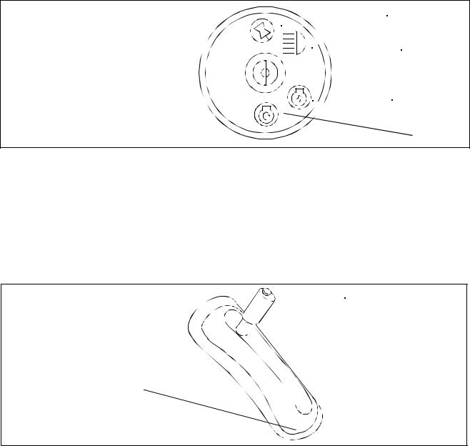
LIFT HANDLE
Height Positions 1 through 7
and L (lock)
Button
 7
7
6
5
4
3
2
1  L
L
Figure 6
The Lift Handle is located on the right fender. It raises and lowers the cutting height of the mower deck used by the Z-series. (See Figure 3) & (See Figure 6)
•1 through 7 (1 - lowest height, 7 - highest height)
•L is the lock out position. The lock position is used when removing the mower deck.
The Choke Lever is located on the Left Control Panel. (See Figure 7) The Choke Lever is operated manually. Having the Choke Lever in the ON position helps the engine to start during initial start-up. During normal operation the Choke Lever should be in the OFF position.
The Throttle Lever is also located on the Left Control Panel and it is used to regulate the engine speed. To get maximum efficiency from cutting, the throttle should be in the FAST position when operating the mower.
(See Figure 7)
8
THROTTLE LEVER AND CHOKE LEVER
Left Control Panel
OFF
Choke Lever |
Throttle Lever |
|
ON
FRONT
Figure 7
PARKING BRAKE
The Parking Brake Pedal is located on the left running board next to the Control Tower. (See Figure 8) It is used to engage the Parking Brake. Engage the Parking Brake when the unit is not in use.
.
Brake Pedal |
|
|
Indicator |
|
|
|
Panel |
||
|
|
|
|
|
|
|
|
|
|
|
|
|
|
|
|
|
|
|
|
|
|
|
|
|
Drive |
|
|
|
Parking Brake |
|||
Handles |
|
|
|
Handle |
|||
|
|
|
|
|
|
|
|
|
|
|
|
|
|
|
|
|
|
|
|
|
|
|
|
Figure 8
DRIVE HANDLES
The Drive Handles (Left and Right) are located at the top of the Control Tower. (See Figure 8) The drive handles are used to move, (propel) steer and stop the Z-series. The drive handles will return toward the neutral position without driver input. However, the driver should place the Drive Handles in the neutral position. Unless the Drive Handles are placed in the neutral position the Z-Series may creep. When the Drive Handles are in the neutral position the unit does not move.
9
When the engine is running, the throttle is set and the Drive Handles are moved from the neutral position, the unit moves in accordance with the driver’s input (push, pull or both). When the driver releases the handles they immediately return towards the neutral position and the unit will slow and stop moving (while the engine continues to run).
The rear wheels propel and steer the unit. The Left Drive Handle controls the Left rear wheel and the Right Drive handle controls the Right rear wheel. Push a handle forward and the respective wheel turns forward. Pull a handle back and the respective wheel turns in reverse.
Each Drive handle has a range in the forward position (push) and the reverse position (pull). If a Drive Handle is moved to the full position (until it stops) the rear wheel turns as fast as the throttle is set. Positions between neutral and full are proportional across the range based on the throttle setting. The Drive Handles can be moved together in the same direction or independent of each other in any combination (i.e. Left push, Right pull).
NOTE: The Drive Handles will return toward neutral when released, but they should be placed in neutral by the driver. If the Drive Handles are not placed in neutral, the tractor may creep.
Speed Control
 Bar
Bar
Wing Nut
Figure 9
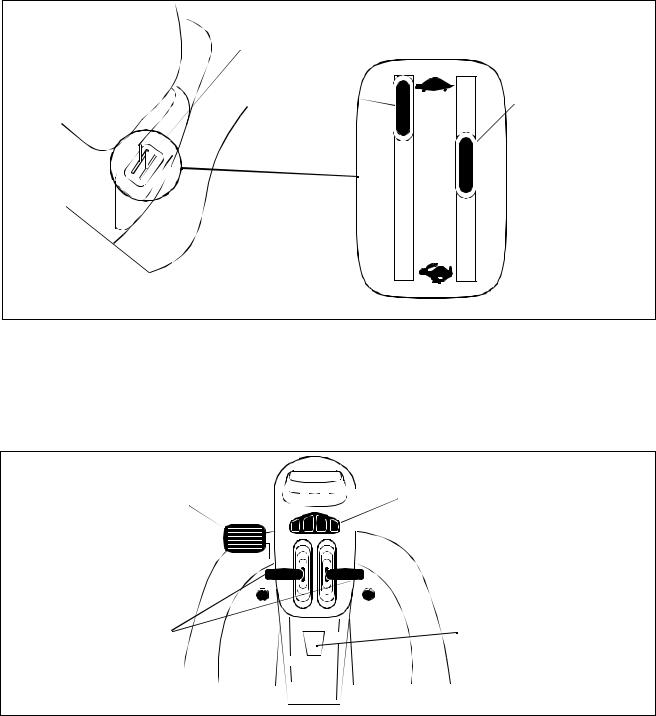
SPEED CONTROL BAR
The Speed Control Bar is connected to the console with two wing nuts. (See Figure 9). It is used as a grab bar for entry or exit from the tractor and allows for pre-set maximum travel speed.
•Loosen the two wing nuts located on either side of the plastic console.
•Rotate speed control bar to desire location.
•Tighten wing nut to secure speed control bar.
NOTE: Limit loosening the wing nuts to 1 1/2 turns. This will insure proper assembly of the screw not visible on the other side of the plastic console. Refer to parts book if screw fell and wing nuts are no longer tightening.
The Speed Control Bar also aids the drive handles in making “perfect U-turns”. Grasping both Drive Handles and the Speed Control Bar at the same time to move forward, release the Left Drive Handle to turn left and then regrasp to continue straight ahead or release the Right Drive Handle to turn right. Refer also to the Quick Reference Chart located in the Operation Section.
10
INDICATOR PANEL
|
|
|
|
|
|
Temperature |
|||||||
Low Engine Oil |
|
|
|
|
|
|
|
|
Battery |
||||
|
|
|
|
|
|
|
|
|
|
|
|
|
|
|
|
|
|
|
|
|
|
|
|
|
|
|
|
|
|
|
|
|
|
|
|
|
|
|
|
|
|
|
|
|
|
|
|
|
|
|
|
|
|
|
|
|
|
|
|
|
|
|
|
|
|
|
|
|
|
|
|
|
|
|
|
|
|
|
|
|
|
|
|
|
|
|
|
|
|
|
|
|
|
|
|
|
|
Figure 10
The Indicator panel is located at the top of the Control Tower. (See Figure 10) There are two or three indicator lights on the panel. When the corresponding light is illuminated it indicates:
•LOW ENGINE OIL: Stop the tractor immediately and check the engine oil level. Continuing to operate with low engine oil can severely damage the engine.
•BATTERY: There is a problem with the charging system or battery. Stop the Z-series and contact your dealer.
•TEMPERATURE: (Liquid Cooled Models only) Stop the engine immediately. Check clean air intake and cooling areas.
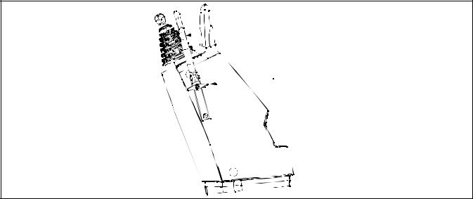
SEAT ADJUSTMENT LEVER
 Seat Adjustment Lever
Figure 11
The Seat Adjustment Lever is located beneath the seat. (See Figure 11) The Seat Adjustment Lever is used to move the seat forward and backward.
1.Pull up on the seat adjustment lever and push the seat forward or back to the desired position.
2.Release the seat adjustment lever so that it locks the seat in place.
WARNING: Do not try to adjust the seat position while operating the Z-Series.
11

SECTION 5: OPERATION
BEFORE OPERATING
1.Study this manual carefully. It has been provided to help you safely operate and maintain this unit.
2.Familiarize yourself with all instruments and controls.
3.Fill the fuel tank according to the engine operator’s manual section.
4.Check the engine oil level according to the engine operators manual section.
5.Check the transmission oil level.
6.Clean the air filter according to the engine operators manual section, if necessary.
7.Check the rear tires for proper inflation pressure. See tire side wall for proper inflation.
8.Adjust the seat for maximum operator comfort, visibility and control.
9.Remove grass and debris from the engine cover panel vents, if necessary.
OPERATING GUIDELINES
•Keep all shields in place and keep away from moving parts.
•NO RIDERS! Keep people and pets at least 75 feet from this unit.
•Always look back before backing.
•Don't point the discharge at people.
•Avoid slopes. This unit can roll over. Use the SLOPE GAUGE to determine safe operating areas.
•Before leaving the seat, disengage the PTO (down), engage the Parking Brake and turn ignition switch to OFF.
•Do not fill gasoline tank when engine is running or while the engine is hot.
STARTING THE ENGINE
The Z-series is equipped with a safety interlock-system with the following features:
•The engine will not crank or start without the Parking Brake fully engaged and the PTO disengaged (down).
•If the operator dismounts the tractor with the PTO in the RUN position, or the Parking Brake disengaged, it automatically shuts the engine off.
WARNING: During operation do not run the engine in confined areas such as storage buildings any longer than necessary. Immediately move the tractor outside into open air.
1.Sit in the seat of the tractor facing forward with your feet straddling the Control Tower.
2.Push the Choke Lever to the full choke position (all the way toward the front of the tractor).
3.Push the Throttle Lever to the fast (Rabbit) position (all the way toward the front of the tractor).
Note: Less choking may be required due to ambient temperature variance and fuel grade. If the engine is warm, choking may not be necessary.
4.Push the power take-off (PTO) switch to OFF.
5.Fully depress the Brake Pedal.
6.Turn the ignition switch to the START position and release it as soon as the engine starts.
Note: Do not engage the starter for more than ten seconds at any one time.
7. Push the Choke Lever to the OFF position (rearward).
Note: In cold weather the starter motor may disengage prematurely. If this happens several times the engine may become flooded.
12

STARTING A FLOODED ENGINE
If the starter disengages several times prematurely, the engine may become flooded. Use the following steps to start a flooded engine:
1.Position the throttle to the idle position.
2.Put the Choke Lever in the OFF position.
3.Turn the ignition switch to the START position and at the same time, slowly move the Choke Lever to the ON position until the engine starts and continues to run.
4.When the engine becomes warm, gradually put the choke lever in the OFF position.
Note: If the engine falters after putting the unit into motion, push the choke forward until the engine runs smoothly. Then gradually pull the choke back as the engine warms.
STOPPING THE ENGINE
1.Bring the tractor to a stop by pulling the drive handles to the neutral position.
2.Push down on the PTO switch (off) if engaged.
3.Set the throttle to the slow position.
4.Allow the engine to idle for a few seconds.
5.Turn the key to the OFF position.
WARNING: Always remove the key from the ignition switch to avoid accidental starting and battery discharge.
OPERATING THE CHOKE LEVER
•ON: Push the lever forward (toward the front of the tractor).
•OFF: Pull the lever back (toward the rear of the tractor).
OPERATING THE THROTTLE LEVER
•FASTER ENGINE SPEED: Push the throttle lever forward toward the Rabbit symbol.
•SLOWER ENGINE SPEED: Pull the throttle lever back toward Turtle symbol.
The Throttle Lever controls the speed of the engine. When set in a given position, it maintains a uniform engine speed. When using power take-off (PTO) equipment (e.g. mower deck) best performance is achieved with the Throttle Lever in the FAST position.
ENGAGING THE PARKING BRAKE
1.Press down on the Brake Pedal and hold.
2.Push down on the Parking Brake Handle in the middle of the Control Tower to lock engagement. (See Figure 8)
Note: The Brake must be engaged when starting the engine.
RELEASING THE PARKING BRAKE
Press down on the Brake Pedal and release.
13
QUICK REFERENCE CHART
The Z-series can turn with a zero radius. The Z-series uses the rear tires to turn. When turning with a zero radius, the rear tires are used as the pivot point. A conventional tractor can make a circle but it needs a turning radius, usually based on the distance between the front and rear wheels. With a shorter overall length and a zero turn radius, the Z-series has excellent maneuverability.
The Z-series does not have a steering wheel, instead drive handles are used to steer and to propel the unit. When the Drive Handles are in the full positions (pull or push) the wheels turn at full speed based on the throttle setting. Positions between neutral and full are proportional across the range based on the throttle setting. This is a departure from what most of us are accustomed. Please take a few minutes to study the diagrams that follows.
RELEASE HANDLES = NEUTRAL - STOP |
|
PULL HANDLES EQUAL BACK = STRAIGHT REVERSE |
PUSH HANDLES EQUAL FORWARD = STRAIGHT |
|
FORWARD |
|
14 |
 Loading...