


1F85-277
Heating & Air Conditioning
7 Day/5-1-1 Programmable/Non-programmable, Auto Changeover, Multi-Stage/Heat Pump Thermostat
INSTALLATION INSTRUCTIONS
Operator: Save these instructions for future use!
FAILURE TO READ AND FOLLOW ALL INSTRUCTIONS CAREFULLY BEFORE INSTALLING OR OPERATING THIS CONTROL COULD CAUSE PERSONAL INJURY AND/OR PROPERTY DAMAGE.
YOUR THERMOSTAT REPLACES
Description |
1F85-277 |
Heat Pump (No Aux. or Emergency Heat) |
Yes |
Heat Pump (with Aux. or Emergency Heat) |
Yes |
Standard Heat & Cooling Systems |
Yes |
Two Stage Heat & Two Stage Cool |
Yes |
Standard Heat Only Systems |
Yes |
Millivolt Heat Only Systems – Floor or Wall Furnaces |
Yes |
Standard Central Air Conditioning |
Yes |
Gas or Oil Heat |
Yes |
Electric Furnace |
Yes |
Hydronic (Hot Water) Zone Heat – 2 Wires |
Yes |
Hydronic (Hot Water) Zone Heat – 3 Wires |
No |
PREPARATIONS
Assemble tools required as shown below.
FLAT BLADE SCREWDRIVER
WIRE CUTTER/STRIPPER
HAND OR POWER DRILL WITH 3/16 INCH DRILL BIT, IF NEEDED
REMOVING OLD THERMOSTAT
! CAUTION
To prevent electrical shock and/or equipment damage, disconnect electric power to system at main fuse or circuit breaker box until installation is complete.
Before removing wires from old thermostat's switching subbase, label each wire with the terminal designation it was removed from.
1.Shut off electricity at the main fuse box until installation is complete. Ensure that electrical power is disconnected.
2.Remove Old Thermostat: A standard heat/cool thermostat consists of three basic parts:
a.The cover, which may be either a snap-on or hinge type.
b.The base, which is removed by loosening all captive screws.
c.The switching subbase, which is removed by unscrewing the mounting screws that hold it on the wall or adaptor plate.
3.Remove the front cover of the old thermostat. With wires still attached, remove wall plate from the wall. If the old thermostat has a wall mounting plate, remove the thermostat and the wall mounting plate as an assembly.
4.Identify each wire attached to the old thermostat.
5.Disconnect the wires from the old thermostat one at a time. DO NOT LET WIRES FALL BACK INTO THE WALL.
6.Install new thermostat using the following procedures.
|
|
|
|
Y2 |
|
|
|
|
C |
|
|
|
|
R |
|
|
|
|
E/W1 |
|
|
|
|
Y1 |
O |
B L |
W2 G |
|
Mounting |
Mounting |
|
|
|
|
|
|
|
Hole |
|
Hole |
|
|
|
|
ELEC. |
|
|
GAS |
|
|
|
|
|
Elec-Gas |
|
ON |
|
AUTO |
Switch |
Figure 1 – Thermostat base
ATTENTION! This product does not contain mercury. However, this product may replace a unit which contains mercury.
Do not open mercury cells. If a cell becomes damaged, do not touch any spilled mercury. Wearing non-absorbent gloves, clean up the spilled mercury and place into a container which can be sealed. If a cell becomes damaged, the unit should be discarded.
Mercury must not be discarded in household trash. When the unit this product is replacing is to be discarded, place in a suitable container and return to White-Rodgers at 2895 Harrison Street, Batesville, AR 72501 for proper disposal.
White-Rodgers is a division |
PART NO. 37-6560A |
|
of Emerson Electric Co. |
||
0430 |
||
www.white-rodgers.com |
MOUNTING AND WIRING
!WARNING
Do not use on circuits exceeding specified voltage. Higher voltage will damage control and could cause shock or fire hazard.
Do not short out terminals on gas valve or primary control to test. Short or incorrect wiring will damage thermostat and could cause personal injury and/or property damage.
Thermostat installation and all components of the system shall conform to Class II circuits per the NEC code.
Electric/Gas Switch (Fan Option)
This thermostat is configured from the factory to operate a heat/ cool, fossil fuel (gas, oil, etc.), forced air system. It is configured correctly for any system that DOES NOT require the thermostat to energize the fan on a call for heat. If you system is an electric heat or heat-pump system that REQUIRES the thermostat to turn on the fan on a call for heat, locate the ELEC/GAS switch on the back of the thermostat (see fig. 1) and switch it to the ELEC position. This will allow the thermostat to energize the fan immediately on a call for heat. If you are unsure if the heating/ cooling system requires the thermostat to control the fan, contact a qualified heating and air conditioning service person.
When the thermostat is configured for Heat Pump, the thermostat will always power the circulator fan on a call for heat in the HEAT mode. The ELEC/GAS switch must be set to match the type of Auxiliary heat your system uses for proper operation in the EMERgency mode.
All wiring diagrams are for typical systems only. Refer to equipment manufacturers’ instructions for specific system wiring information.
! CAUTION
Take care when securing and routing wires so they do not short to adjacent terminals or rear of thermostat. Personal injury and/or property damage may occur.
Attach Thermostat Base to Wall
1.Remove the packing material from the thermostat. Gently pull the cover straight off the base. Forcing or prying on the thermostat will cause damage to the unit.
2.Connect wires beneath terminal screws on base using appropriate wiring schematic (see figs. 2 through 4).
3.Place base over hole in wall and mark mounting hole locations on wall using base as a template.
4.Move base out of the way. Drill mounting holes.
5.Fasten base loosely to wall, as shown in fig. 1, using two mounting screws. Place a level against bottom of base, adjust until level, and then tighten screws. (Leveling is for appearance only and will not affect thermostat operation.) If you are using existing mounting holes, or if holes drilled are too large and do not allow you to tighten base snugly, use plastic screw anchors to secure subbase.
6.Push excess wire into wall and plug hole with a fireresistant material (such as fiberglass insulation) to prevent drafts from affecting thermostat operation.
Battery Location
2 “AA” alkaline batteries are included in the thermostat at the factory with a battery tag to prevent power drainage. You must remove the battery tag to engage the batteries.
If “BATT” is displayed, the batteries are low and should be replaced with fresh “AA” Energizer® alkaline batteries. To replace batteries, press system button to OFF, install the batteries along the top of the base (see Fig. 1). The batteries must be installed with the positive (+) end to the left.
|
|
|
|
|
|
|
|
|
|
|
|
|
|
|
E/W1 |
|
|
|
|
|
THERMOSTAT |
||||
O |
B |
Y2 |
|
|
|
|
|
|
|
C * |
|
|
|
|
|
||||||||||
Y1 |
|
G |
|
W2 |
|
|
|
L |
R |
||||||||||||||||
|
|
|
|
|
|
|
|
|
|
|
|
|
|
|
|
|
|
SYSTEM |
|
|
|
SYSTEM |
|||
|
|
|
|
|
|
|
|
|
|
|
|
|
|
|
|
|
|
|
|
|
|||||
|
|
|
|
|
|
|
|
|
|
|
|
|
|
|
|
|
|
|
|
|
|
||||
Reversing Valve |
|
Reversing Valve |
|
2nd Stage |
|
|
|
|
|
|
|
|
|
|
|
|
|
|
|||||||
|
|
|
|
|
Fan |
|
|
|
|
|
|
MONITOR |
|
|
|
|
|
|
|||||||
|
|
|
|
|
|
Emergency |
|
|
|
|
|
|
|
|
|||||||||||
Energized in Cool |
|
Energized in Heat, |
|
Compressor |
|
Compressor |
|
|
Aux |
|
|
|
SWITCH |
|
|
|
|
||||||||
|
|
|
|
Relay |
|
|
Heat |
|
|
|
|
|
|
||||||||||||
Mode |
|
Off, Emergency |
|
|
|
|
|
|
Heat |
|
|
|
|
|
|
|
|
|
|
|
|||||
|
|
|
|
|
Contactor |
|
|
|
|
Relay |
|
|
|
|
|
|
|
|
|
|
|||||
|
|
|
Mode |
|
|
|
|
|
|
|
Relay |
|
|
|
24 VAC |
|
|
|
Hot |
||||||
|
|
|
|
|
|
|
|
|
|
|
|
|
|
|
|
|
|
|
|
|
120 VAC |
||||
|
|
|
|
|
|
|
|
|
|
|
|
|
|
|
|
|
|
|
|
|
|
|
|
|
Neutral |
|
|
|
|
|
|
|
|
|
|
|
|
|
|
|
|
|
|
|
|
|
|
|
|
|
|
|
|
|
|
|
|
|
|
|
|
|
|
|
|
|
|
|
|
|
|
|
TRANSFORMER |
||||
|
|
|
|
|
|
|
|
|
|
|
|
|
|
|
|
|
|
(Class II Current Limited) |
|||||||
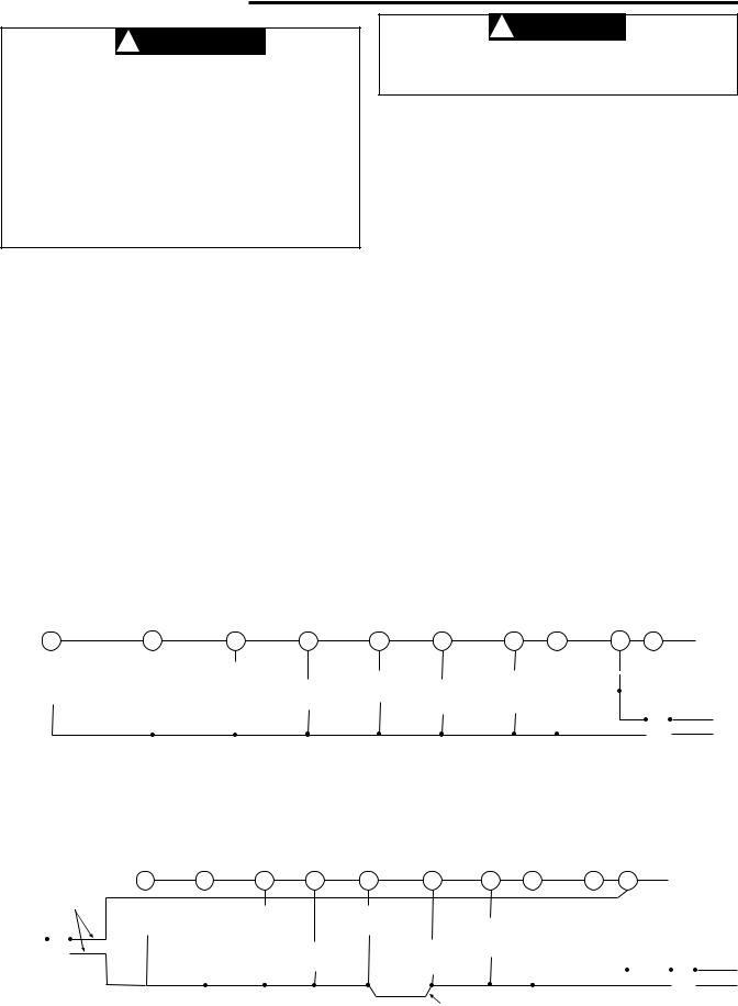
Figure 2. Typical wiring diagram for single transformer heat pump systems
*The 24 volt neutral connection to terminal C on the thermostat is not required if you replace the batteries once a year with fresh “AA” Energizer® alkaline batteries.
|
|
|
|
|
|
|
|
|
|
|
|
|
|
|
|
|
|
NOTE |
|
|
|
|
|
|
|
|
|
|
|
|
|
|
|
|
|
|
|
|
|
|
|
|
|
|
|
|
|
|
|
|
|
|
If safety circuits are in only one of the systems, remove |
|
|
|
|
|
|
|
|
|
|
|
|
|
|
||||||||||||
|
|
|
|
|
|
|
|
|
|
|
|
|
the transformer of the system with NO safety circuits. |
|
|
|
|
|
|
|
|
|
|
|
|
|
|
||||||||||||
|
|
|
|
|
|
|
|
|
|
|
|
|
|
|
|
|
|
|
|
|
|
|
|
|
|
|
|
|
|
|
|
|
|
|
|
|
|
||
|
|
|
|
|
|
|
|
|
|
|
|
|
|
|
|
|
|
|
|
|
|
|
E/W1 |
|
|
|
|
|
THERMOSTAT |
|
|||||||||
|
|
|
|
|
|
|
|
|
|
|
|
|
|
|
|
|
|
|
|
|
|
|
|
|
C * |
|
|
|
|
|
|
||||||||
|
|
|
|
|
|
|
O |
B |
Y2 |
|
|
Y1 |
|
G |
W2 |
|
|
|
|
|
L |
R |
|
||||||||||||||||
CUT AND |
|
|
|
|
|
|
|
|
|
|
|
|
|
|
|
|
|
|
|
|
|
|
|
|
|
|
|
SYSTEM |
|
||||||||||
|
|
|
|
|
|
|
|
|
|
|
|
|
|
|
|
|
|
|
|
|
|
|
|
|
|
|
|
||||||||||||
TAPE OFF! |
|
|
|
|
|
|
|
|
|
|
|
|
|
|
|
|
|
|
|
|
SYSTEM |
|
|
|
|
|
|
|
|
|
|
|
|||||||
|
|
|
|
|
|
|
Reversing |
Reversing |
2nd Stage |
|
|
Fan |
|
|
|
|
|
|
|
|
|
|
Limit or |
|
|
|
|
|
|
|
|||||||||
|
|
|
|
|
|
|
Valve |
|
|
|
|
|
|
|
|
|
|
MONITOR |
|
|
|
|
|
||||||||||||||||
|
|
|
|
|
|
|
Valve |
Compressor |
|
|
Relay |
|
|
|
|
Emergency |
|
|
SWITCH |
|
|
Safety |
|
|
|
|
|
|
|
||||||||||
HOT |
|
|
|
|
Energized in |
|
|
|
|
|
|
|
|
|
|
|
|
|
|
|
|
|
|||||||||||||||||
|
|
|
|
|
|
|
Energized in |
|
|
|
|
|
|
|
|
|
|
|
|
Heat |
|
|
|
|
|
|
Switches |
|
|
||||||||||
120 VAC |
|
|
|
|
|
24 VAC |
Cool Mode |
Heat, Off, |
|
|
|
Compressor |
|
|
|
|
Aux |
|
|
Relay |
|
|
|
|
|
|
|
|
|
|
|
|
|
|
|
||||
|
|
|
|
|
|
|
Emergency |
|
|
|
|
|
|
|
Heat |
|
|
|
|
|
|
|
|
|
|
|
|
|
|
|
|
|
|
|
|||||
|
|
|
|
|
|
|
|
|
|
|
|
|
|
|
|
|
|
|
|
|
|
|
|
|
|
|
|
|
|
|
|
|
|||||||
NEUTRAL |
|
|
|
|
|
|
Mode |
|
|
|
|
Contactor |
|
|
|
|
Relay |
|
|
|
|
|
|
|
|
|
|
|
|
|
|
|
|
|
|
Hot |
|||
|
|
|
|
|
|
|
|
|
|
|
|
|
|
|
|
|
|
|
|
|
|
|
|
|
|
|
|
|
|
|
|
|
|
|
|
|
|
||
|
|
|
|
|
|
|
|
|
|
|
|
|
|
|
|
|
|
|
|
|
|
|
|
|
|
|
|
|
|
24 VAC |
|
|
|
|
|
120 VAC |
|||
|
|
|
|
|
|
|
|
|
|
|
|
|
|
|
|
|
|
|
|
|
|
|
|
|
|
|
|
|
|
|
|
|
|
|
|
|
|||
|
|
|
|
|
|
|
|
|
|
|
|
|
|
|
|
|
|
|
|
|
TWO COMMONS MUST |
|
|
|
|
|
|
|
|
|
|
|
|
Neutral |
|||||
|
|
|
|
|
|
|
|
|
|
|
|
|
|
|
|
|
|
|
|
|
|
|
|
|
|
|
|
|
|
|
|
|
|||||||
|
|
|
|
|
|
|
|
|
|
|
|
|
|
|
|
|
|
|
|
|
|
|
|
|
|
|
|
|
|
|
|
|
|
||||||
|
|
|
|
|
|
|
|
|
|
|
|
|
|
|
|
|
|
|
|
|
|
|
|
|
|
|
TRANSFORMER |
||||||||||||
|
|
|
|
|
|
|
|
|
|
|
|
|
|
|
|
|
|
|
|
|
BE JUMPERED TOGETHER! |
|
|
||||||||||||||||
|
|
|
|
|
|
|
|
|
|
|
|
|
|
|
|
|
|
|
|
|
|
(Class II Current Limited) |
|||||||||||||||||
|
|
|
|
|
|
|
|
|
|
|
|
|
|
|
|
|
|
|
|
|
|
|
|
|
|
|
|
|
|
|
|
||||||||
Figure 3. Typical wiring diagram for two transformer heat pump systems with NO safety circuits
*The 24 volt neutral connection to terminal C on the thermostat is not required if you replace the batteries once a year with fresh “AA” Energizer® alkaline batteries.
2
WIRING DIAGRAMS
NOTE
Polarity must be observed. If the HOT side of the second transformer is jumpered to the COMMON side of the first transformer a short will be made. Damage to equipment will occur when power is restored.
|
|
|
|
|
|
|
|
|
|
|
|
|
|
|
E/W1 |
|
|
|
|
|
|
|
|
|
|
|
|
THERMOSTAT |
|
|
|
|
|
|||||||
O |
B |
|
|
|
|
|
|
|
|
|
|
C * |
|
|
|
|
|
|
|
|
|
|
|
|
|
|
|
|
|
|||||||||||
Y2 |
|
Y1 |
|
G |
|
W2 |
|
|
|
|
L |
R |
|
|
|
|
|
|
|
SYSTEM |
|
|
|
|
|
|
||||||||||||||
|
|
|
|
|
|
|
|
|
|
|
|
|
|
|
|
|
|
|
|
|
|
|
|
|
|
|
|
|
|
|
|
|
Limit or |
|
|
|||||
|
|
|
|
|
|
|
|
|
|
|
|
|
|
|
|
|
|
|
|
|
|
|
|
|
Limit or |
|
|
|
|
|
|
|
|
|
|
Safety |
HOT |
|||
|
|
Reversing |
|
|
|
|
|
|
|
|
|
|
|
|
|
|
|
|
|
|
|
|
Safety |
|
24 VAC |
|
|
|
120 VAC |
Switches |
|
|
||||||||
|
|
|
|
|
|
|
|
|
|
|
|
|
|
|
|
|
|
|
|
|
|
|
|
|||||||||||||||||
|
|
|
|
|
|
|
|
|
|
|
|
Emergency |
|
|
SYSTEM |
|
|
|
|
Switches |
|
|
|
|
|
|
|
|
||||||||||||
Reversing |
|
Valve |
|
2nd Stage |
|
|
|
Fan |
|
|
|
Heat |
|
|
MONITOR |
|
|
|
|
|
|
|
|
|
|
|
|
|
|
|
|
|
|
NEUTRAL |
||||||
|
Energized in |
|
|
|
|
|
|
|
|
|
|
|
|
|
|
|
|
|
|
|
|
|
|
|
|
|
|
|
||||||||||||
Valve |
|
Heat, Off, |
|
Compressor |
|
|
Relay |
|
|
|
Relay |
|
|
SWITCH |
|
|
|
|
24 VAC |
|
|
|
|
Auxiliary |
|
|
|
NOTE |
|
|||||||||||
|
|
|
|
|
|
|
|
|
|
|
|
|
|
|
|
|
|
|
|
|||||||||||||||||||||
Energized in |
|
|
|
|
|
|
|
|
|
|
|
|
|
|
|
|
|
|
|
|
|
ACCESSORY |
|
|
Heating |
|
|
|
|
|||||||||||
|
|
|
|
|
|
|
Aux |
|
|
|
|
|
|
|
|
|
|
|
||||||||||||||||||||||
Cool Mode |
|
Emergency |
|
|
|
Compressor |
|
|
|
|
|
|
|
|
|
|
|
|
|
|
RELAY N.O. |
|
Transformer |
The accessory relay scheme |
||||||||||||||||
|
|
Mode |
|
|
|
|
Contactor |
|
|
|
Heat |
|
|
|
|
|
|
|
|
|
|
|
CONTACT |
|
|
(Class II |
|
is required when safety |
||||||||||||
|
|
|
|
|
|
|
|
|
|
|
|
|
|
|
|
|
|
|
|
|
|
|
||||||||||||||||||
|
|
|
|
|
|
|
|
|
Relay |
|
|
|
|
|
|
|
|
|
|
|
|
|
|
|
|
|
Current Limited) |
|||||||||||||
|
|
|
|
|
|
|
|
|
|
|
|
|
|
|
|
|
|
|
|
|
|
|
|
COMMON |
|
circuits exist in both systems. |
||||||||||||||
|
|
|
|
|
|
|
|
|
|
|
|
|
|
|
|
|
|
|
|
|
|
|
|
|
|
|
|
|
|
|
|
|
|
|
|
|
|
|
|
|
|
|
|
|
|
|
|
|
|
|
|
|
|
|
TWO COMMONS MUST |
|
|
|
|
|
|
Limit or |
|
|
|
|
|
|
|
|
|
Limit or |
|
|
|
||||||
|
|
|
|
|
|
|
|
|
|
|
|
|
|
|
|
|
|
|
|
|
|
|
|
|
|
|
|
|||||||||||||
|
|
|
|
|
|
|
|
|
|
|
|
|
|
BE JUMPERED TOGETHER! |
|
|
|
Safety |
|
|
|
|
|
|
|
|
|
Safety |
HOT |
|||||||||||
|
|
|
|
|
|
|
|
|
|
|
|
|
|
|
|
|
|
|
|
|
|
|
|
Switches |
24 VAC |
|
|
|
|
120 VAC |
Switches |
|||||||||
|
|
|
|
|
|
|
|
|
|
|
|
|
|
|
|
|
|
|
|
|
|
|
|
|
|
|
|
|
|
|
|
|
|
|||||||
|
|
|
|
|
|
|
|
|
|
|
|
|
|
|
|
|
|
|
|
|
|
COMMON |
|
|
|
|
|
|
|
|
|
|
|
|||||||
|
|
|
|
|
|
|
|
|
|
|
|
|
|
|
|
|
|
|
|
|
|
|
|
|
|
|
|
|
|
|
|
|
|
|
|
|
NEUTRAL |
|||
|
|
|
|
|
|
|
|
|
|
|
|
|
|
|
|
|
|
|
|
|
|
|
|
|
|
|
|
|
|
|
|
|
|
|
|
|||||
|
|
|
|
|
|
|
|
|
|
|
|
|
|
|
|
|
|
|
|
|
|
|
|
|
|
|
|
|
|
|
|
|
|
|
|
|
|
|||
|
|
|
|
|
|
|
|
|
|
|
|
|
|
|
|
|
|
|
|
|
|
|
|
|
|
Heat Pump Transformer |
|
|
|
|
|
|
||||||||
|
|
|
|
|
|
|
|
|
|
|
|
|
|
|
|
|
|
|
|
|
|
|
|
|
|
(Class II Current Limited) |
|
|
|
|
|
|||||||||
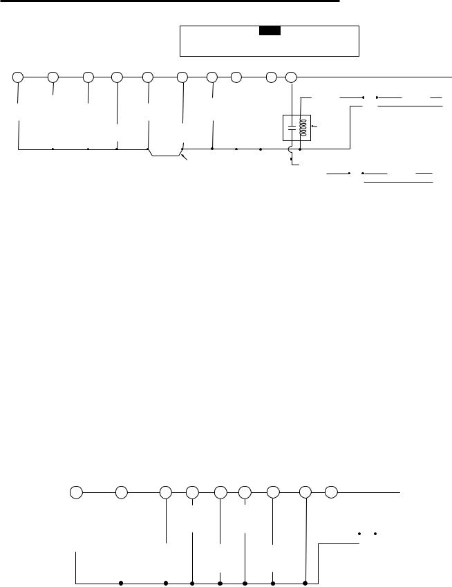
Figure 4. Typical wiring diagram for two transformer heat pump systems with safety circuits in BOTH systems
*The 24 volt neutral connection to terminal C on the thermostat is not required if you replace the batteries once a year with fresh “AA” Energizer® alkaline batteries.
Heat Pump Terminal Outputs
Refer to equipment manufacturers' instructions for specific system wiring information.
You can configure the thermostat for use with the following heat pump system types:
HEAT PUMP TYPE 1. Single stage compressor system; gas or electric backup.
This thermostat is designed to operate a single-transformer system. If you have a two-transformer system, cut and tape off
one transformer. If transformer safety circuits are in only one of the systems, remove the transformer of the system with NO safety circuits. If required, replace remaining transformer with a 75VA Class II transformer. After disconnecting one transformer, the two commons must be jumpered together.
Use the terminal output information below to help you wire the thermostat properly for your heat pump system. After wiring, see CONFIGURATION section for proper thermostat configuration.
|
|
|
|
THERMOSTAT TERMINALS (HEAT PUMP) |
|
|
||||
SYSTEM |
L |
C* |
R |
W2 |
E/W1 |
Y2 |
Y1 |
G |
O |
B |
Heat |
Malfunction |
24 Volt |
24 Volt |
HP 1 and |
Emergency |
No |
Heat and |
Blower/Fan Energized |
Energized |
Energized |
Pump 1 |
Light |
(Common) |
(Hot) |
Emergency |
Mode |
Output |
Cool mode |
on call for Heat |
in Cool |
in Heat |
|
|
|
|
2nd stage |
1st stage |
|
1st stage |
and Cool |
Mode |
OFF |
|
|
|
|
|
||||||
Heat |
|
|
|
HP 2 |
|
2nd |
(compressor) |
Set GAS/ELEC switch |
|
Emergency |
Pump 2 |
|
|
|
3rd stage |
|
stage |
|
for Emergency mode |
|
mode |
|
|
|
|
|
|
compressor |
|
|
|
|
*The 24 volt neutral connection to terminal C on the thermostat is not required if you replace the batteries once a year with fresh “AA” Energizer® alkaline batteries.
|
|
|
|
|
|
|
|
|
|
|
|
|
|
E/W1 |
C * |
|
THERMOSTAT |
||||||||
|
|
|
|
|
|
|
|
|
|
Y2 |
|
|
|
|
|
|
|||||||||
O |
B |
Y1 |
|
G |
|
|
|
W2 |
R |
SYSTEM |
|||||||||||||||
|
|
|
|
|
|
|
|
|
|
|
|
|
|
|
|
|
|
|
|
||||||
|
|
|
|
|
|
|
|
|
|
|
|
|
|
|
|
|
|
|
|
||||||
|
|
|
|
|
|
|
|
|
|
|
|
|
|
|
|
|
|
|
|
|
|
|
|
||
|
|
|
|
|
|
|
|
|
Compressor |
|
|
Heat |
|
|
|
|
|
|
|
|
|
|
|||
|
|
|
|
|
|
|
|
|
Contactor |
|
|
Relay |
|
|
|
|
|
|
|
|
|
|
|||
Reversing |
|
Reversing |
|
|
|
|
|
|
|
|
|
|
|
|
|
|
|
|
|||||||
|
|
|
|
|
Stage 2 |
|
Stage 1 |
|
|
|
|
|
|
|
|
|
Hot |
||||||||
Valve |
|
Valve |
|
|
|
|
|
|
|
|
|
|
|
|
|
|
|||||||||
|
|
|
|
|
|
|
|
|
|
|
|
|
|
|
|
|
|
|
|
|
|
|
|
|
|
Energized in |
|
Energized in |
|
|
|
|
|
|
|
|
|
|
|
|
|
|
24 VAC |
|
|
|
|
|
120 VAC |
||
Cool Mode |
|
Heat Mode |
|
Compressor |
|
|
|
|
|
|
Heat |
|
|
|
|
|
|
|
|
|
|||||
Fan |
|
|
|
|
|
|
|
Neutral |
|||||||||||||||||
|
|
|
Off Emergency |
|
Contactor |
|
|
|
|
|
Relay |
|
|
|
|
|
|
|
|||||||
|
|
|
|
|
|
Relay |
|
|
|
|
|
TRANSFORMER |
|||||||||||||
|
|
|
|
|
|
Stage 1 |
|
|
|
|
|
|
Stage 2 |
|
|
||||||||||
|
|
|
|
|
|
|
|
|
|
|
|
|
|
|
(Class II, Current Limited) |
||||||||||
|
|
|
|
|
|
|
|
|
|
|
|
|
|
|
|
|
|
|
|
|
|
|
|
|
|
Figure 5. Typical wiring diagram for single transformer multi-stage systems
*The 24 volt neutral connection to terminal C on the thermostat is not required if you replace the batteries once a year with fresh “AA” Energizer® alkaline batteries.
3
Multi-Stage Terminal Outputs
Refer to equipment manufacturers' instructions for specific system wiring information.
You can configure the thermostat for use with either multi-stage electric heat systems or multi-stage gas systems. When configured for electric heat, the G terminal (blower/fan) will be energized on a call for heat.
This thermostat is designed to operate a single-transformer system. If you have a two-transformer system, cut and tape off
one transformer. If transformer safety circuits are in only one of the systems, remove the transformer of the system with NO safety circuits. If required, replace remaining transformer with a 75VA Class II transformer. After disconnecting one transformer, the two commons must be jumpered together.
Use the terminal output information below to help you wire the thermostat properly for your multi-stage system. After wiring, see CONFIGURATION section for proper thermostat configuration.
|
|
|
|
THERMOSTAT TERMINALS (MULTI-STAGE) |
|
|
||||
SYSTEM |
L |
C* |
R |
W2 |
E/W1 |
Y2 |
Y1 |
G |
O |
B |
Multi-stage |
Malfunction |
24 Volt |
24 Volt |
Heat Mode |
Heat mode |
Cool Mode |
Cool Mode |
Blower/Fan Energized |
Energized |
Energized |
|
Light |
(Common) |
(Hot) |
2nd stage |
1st stage |
2nd stage |
1st stage |
on call for Cool (and |
in Cool |
in Heat, Off, |
|
|
|
|
|
|
|
|
Heat if configured |
Mode |
Emergency |
|
|
|
|
|
|
|
|
to Electric Heat) |
|
Modes |
|
|
|
|
|
|
|
|
|
|
|
*The 24 volt neutral connection to terminal C on the thermostat is not required if you replace the batteries once a year with fresh “AA” Energizer® alkaline batteries.
CHECK THERMOSTAT OPERATION
NOTE
To prevent static discharge problems, touch side of thermostat to release static build-up before touching any keys.
If at any time during testing your system does not operate properly, contact a qualified serviceperson.
Fan Operation
If your system does not have a G terminal connection, skip to
Heating System.
1.Turn on power to system.
2.Move FAN switch to ON position. The blower should begin to operate.
3.Move FAN switch to AUTO position. The blower should stop immediately.
! CAUTION
Do not allow the compressor to run unless the compressor oil heaters have been operational for 6 hours and the system has not been operational for at least 5 minutes.
Heating System
1.Press SYSTEM button to select the Flame icon ( ). If the auxiliary heating system has a standing pilot, be sure to light it.
2.Press  to adjust thermostat setting to 1° above room temperature. The heating system should begin to
operate. The display should show “STG1”. However, if the setpoint temperature display is flashing, the compressor lockout feature is operating (see Configuration menu, item 5).
3.Adjust temperature setting to 3° above room temperature. If your system configuration is set at MS2, HP2 or HP1, the auxiliary heat system should begin to operate and the display should show “STG1+2”.
4.Press  to adjust the thermostat below room temperature. The heating system should stop operating.
Emergency System
EMER bypasses the Heat Pump to use the heat source wired to terminal E on the thermostat. EMER is typically used when compressor operation is not desired, or you prefer back-up heat only.
1.Press SYSTEM button to select EMER. “EMER” will flash on the display.
2.Press  to adjust thermostat setting above room temperature. The Aux. heating system will begin to
operate. The display will show “STG1” flashing “EMER”
and Flame icon ( ) to indicate that the Aux. system is operating.
3.Adjust temperature setting to 3° above room temperature. The auxiliary heat system should begin to operate and the display should show “STG1+2”.
4.Press  to adjust the thermostat below room temperature. The Aux. heating system should stop operating.
! CAUTION
To prevent compressor and/or property damage, if the outdoor temperature is below 50°F, DO NOT operate the cooling system.
Cooling System
1.Press SYSTEM button to select the Snowflake icon ( ).
).
2.Press  to adjust thermostat setting below room temperature. The blower should come on immediately on high speed, followed by cold air circulation. The display should show “STG1”.
3.Adjust temperature setting to 3° below room temperature. The second stage cooling should begin to operate and the display should show “STG1+2”.
4.Press  to adjust the temperature setting above room temperature. The cooling system should stop operating.
4
 Loading...