


1F86-0471
Installation 2
Wiring Connections 2
Thermostat Quick Reference 3
Installer Configuration Menu 4
Operating Your Thermostat 6
Programming 6
Troubleshooting 8
www.white-rodgers.com
80 Series Thermostat with80 Series Thermostat with
80 Series Thermostat with80 Series Thermostat with
80 Series Thermostat with
Automatic Heat/Cool Changeover OptionAutomatic Heat/Cool Changeover Option
Automatic Heat/Cool Changeover OptionAutomatic Heat/Cool Changeover Option
Automatic Heat/Cool Changeover Option
PART NO. 37-6749A
0604
Single Stage or Heat Pump
Installation and Operating Instructions for Model:
APPLICATIONS
Description
Gas or Oil Heat Yes
Electric Furnace Yes
Heat Pump (No Aux. or Emergency Heat) Yes
Heat Pump (with Aux. or Emergency Heat) No
Systems with up to 3 Stages Heat, 2 Stages Cool No
Heat Only Systems Yes
Millivolt Heat Only Systems – Floor or Wall Furnaces Yes
Cool Only Systems Yes
Hydronic (Hot Water) Zone Heat – 2 Wires Yes
Hydronic (Hot Water) Zone Heat – 3 Wires Yes
THERMOSTAT APPLICATION GUIDE
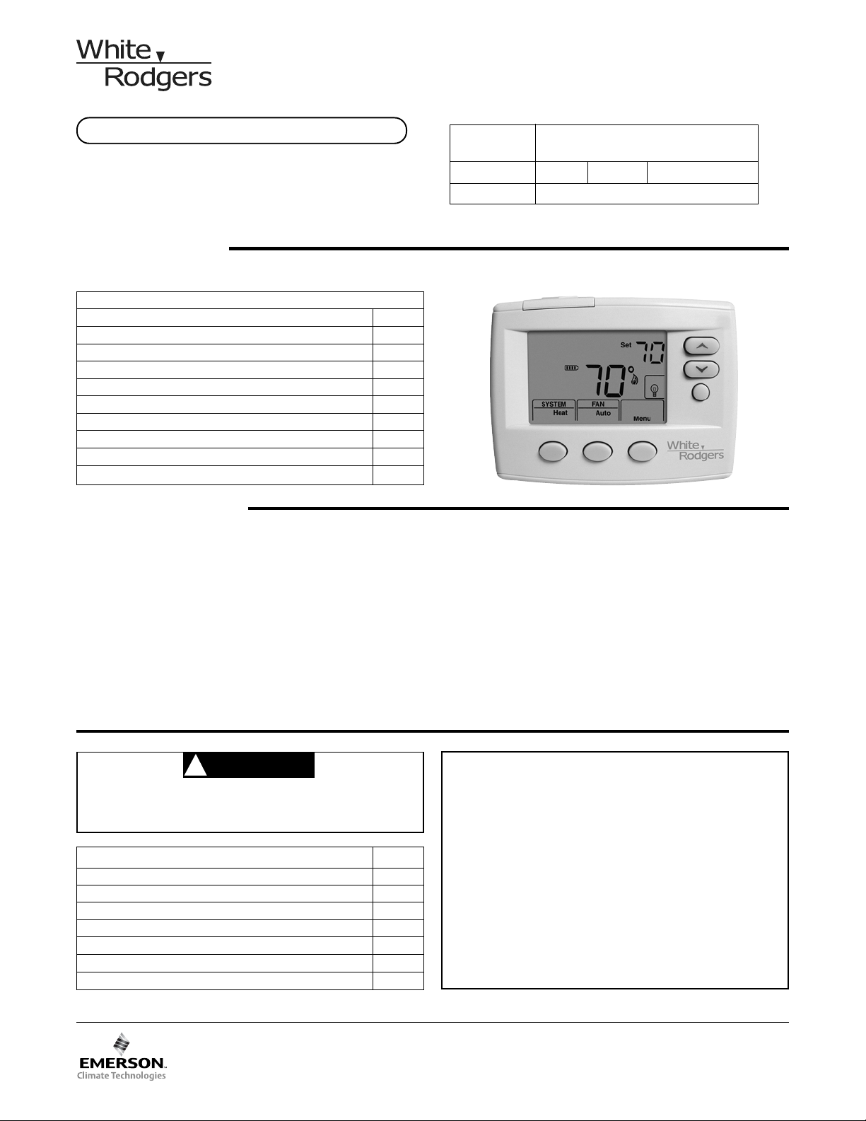
1F86-0471 Thermostat
SPECIFICATIONS
Electrical Rating:
Battery Power . . . . . . . . . . . . . . . . . . . . . . . . . mV to 30 VAC, NEC Class II, 50/60 Hz or DC
Input-Hardwire . . . . . . . . . . . . . . . . . . . . . . . . 20 to 30 VAC
Terminal Load . . . . . . . . . . . . . . . . . . . . . . . . . . . . 1.0 A per terminal, 1.5A maximum all terminals combined
Setpoint Range . . . . . . . . . . . . . . . . . . . . . . . . . . . 45° to 90°F (7° to 32°C)
Differential (Single Stage) . . . . . . . . . . . . . . . . . . . Heat 0.6°F; Cool 1.2°F (adjustable)
Differential (Heat Pump) . . . . . . . . . . . . . . . . . . . . Heat 1.2°F; Cool 1.2°F (adjustable)
Operating Ambient . . . . . . . . . . . . . . . . . . . . . . . . . 32° to +105°F (0° to +41°C)
Operating Humidity . . . . . . . . . . . . . . . . . . . . . . . . 90% non-condensing max.
Shipping Temperature Range . . . . . . . . . . . . . . . . -4° to +150°F (-20° to +65°C)
Dimensions Thermostat . . . . . . . . . . . . . . . . . . . . . 3.4"H x 4.4"W x 1.3"D
To prevent electrical shock and/or equipment dam-
age, disconnect electric power to system at main fuse
or circuit breaker box until installation is complete.
CAUTION
!
ATTENTION: MERCURY NOTICE
This product does not contain mercury. However, this
product may replace a product that contains mercury.
Mercury and products containing mercury must not be
discarded in household trash. Do not touch any spilled
mercury. Wearing non-absorbent gloves, clean up any
spilled mercury and place in a sealed container. For proper
disposal of a product containing mercury or a sealed
container of spilled mercury, place it in a suitable shipping
container and send it to:
White-Rodgers
2895 Harrison Street
Batesville, AR 72501
Index Page
Model Programming Choices
1F80-0471
5/2 Day 5/1/1 Day Non-Prog rammable
1F86-0471 Non-Programmable
Save these instructions for future use!
FAILURE TO READ AND FOLLOW ALL INSTRUCTIONS
CAREFULLY BEFORE INSTALLING OR OPERATING THIS
CONTROL COULD CAUSE PERSONAL INJURY AND/OR
PROPERTY DAMAGE.
2
WIRING CONNECTIONS
Refer to equipment manufacturers' instructions for specific
system wiring information. After wiring, see CONFIGURA-
TION section for proper thermostat configuration.
WARNING
!
Thermostat installation and all components of the
control system shall conform to Class II circuits per
the NEC code.
INSTALLATION
Once fully down, snap the door back into position. To
replace the batteries, set system to OFF, following the
instructions above.
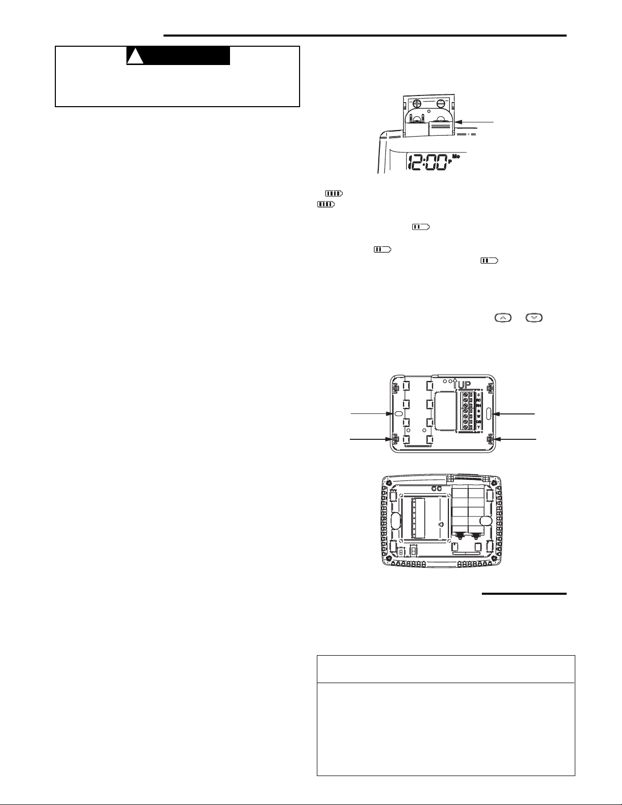
Figure 2 – Thermostat base and rear view of thermostat
Remove Old Thermostat
A standard heat/cool thermostat consists of three basic parts:
1.The cover, which may be either a snap-on or hinge type.
2.The base, which is removed by loosening all captive screws.
3.The switching subbase, which is removed by unscrewing
the mounting screws that hold it on the wall or adapter
plate. Before removing wires from old thermostat,
label each wire with the terminal designation from
which it was attached. Disconnect the wires from the old
thermostat one at a time. Do not let wires fall back into
the wall.
Installing New Thermostat
1. Pull the ther mostat body off the thermosta t base. Forcing
or prying on the ther mosta t will cause damage to the unit.
2. Place base over hole in wall and mark mounting hole
locations on wall using base as a template.
3. Move base out of the way. Drill mounting holes. If you
are using existing mounting holes and the holes drilled
are too large and do not allow you to tighten base snug-
ly, use plastic screw anc hors to secure the base.
4. Fasten base snugly to wall using mounting holes shown
in Figure 2 and two mounting screws. Leveling is for
appearance only and will not affect thermostat operation.
5. Connect wires to ter minal bloc k on base.
6. Push excess wire into wall and plug hole with a fire re-
sistant material (such as fiberglass insulation) to prevent
drafts from affecting thermostat operation.
7. Carefully line the ther mostat up with the base and sna p
into place.
SS/HP Switch
(Conventional or Heat Pump Selection)
The SS/HP switch is factory set to the SS position. In this
position, thermostat is configured as conventional single
stage. If you have a single stage heat pump system, switch
SS/HP to HP position (see figure 2).
Terminal
Designation Description
O/B . . . . .Changeover valve for heat pump
Y . . . . . . Compressor Relay
W . . . . . . Heat Relay
G . . . . . .Fan Relay
RH . . . . .Power for Heating
RC . . . . .Power for Cooling
C . . . . . . Common wire from secondary side of cooling
system transformer or heat only system transformer
2
TERMINAL DESIGNATION DESCRIPTIONS
Electric/Gas Switch (Fan Option)
The ELEC/GAS switch is factory set to the GAS position. In
this position, the thermostat will not power the circulator fan
on a call for heat, but will power the circulator on a call for
cool.
If your system requires that the thermostat power the
circulator fan on a call for heat, this switch should be set to
the ELEC position. Typically, gas and oil heating systems do
not require the thermostat to power the circulator fan during
a call for heat. If your heat is gas or oil, the switch should be
set to the GAS position.
When the thermostat is configured for Heat Pump, the
thermostat will always power the circulator fan on a call for
heat in the HEAT mode.
“AA” Alkaline Batteries
Figure 1 – Battery door shown open
Mounting
Hole
Mounting
Hole
Place Level
across
Mounting Tabs
(for appearance only)
Place Level
across
Mounting Tabs
(for appearance only)
SS
HP
GAS
ELEC
Batteries
2 "AA" alkaline batteries are included in the thermosta t. To
install the batteries, pull the battery door as shown by the
arrow and lift open. Using the polarity indicated inside the
battery door, insert the batteries. To close the battery door,
swing the door down while pulling in the direction of arrow.
Thermostat can be powered by system AC power or Battery.
If is displayed the thermostat is battery powered. If
is not displayed, thermostat is system powered with
optional battery bac k-up. When battery power remaining is
approximately half the will be displayed. If the home is
going to be unoccupied for an extended period (over 3
months ) and is displayed, the batteries should be
replaced before leaving. When Change is displayed,
install fresh “AA” alkaline batteries immedia tely. The setpoint
temperature will offset by 10 degrees (10 degrees cooler in
heat mode / 10 degrees warmer in Cool mode) when less
than two months of battery life remain. (If of fset occur s the
normal setpoint can be manually reset with
or , if
batteries are not replaced another offset will occur within two
days).
3
Displays the power level of the
2 "AA" batteries:
indicates good power level.
indicates batteries at about
half power. “Change ” indicates
batteries are low and should be
replaced with 2 new “AA” Alkaline
batteries.
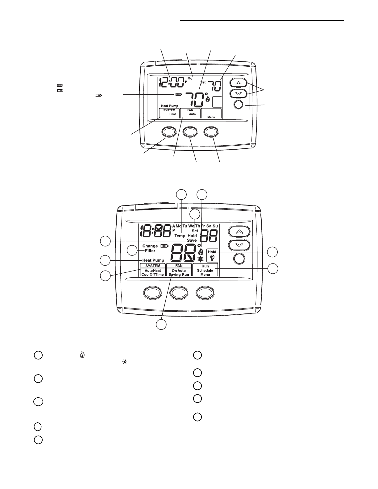
Time
Day of Week
Setting
Temperature
Room
Temperature
Temperature Up/Down
HOLD Button
SYSTEM
Button
FAN
Button
SYSTEM
Indicator
FAN
Indicator
MENU/SCHEDULE/RUN
Button
Home Screen Description
Figure 4 – Home Screen Display
Figure 5 – Programming & Configuration Items
10
1
2
3
4
5
6
7
8
9
THERMOSTAT QUICK REFERENCE
10
Displays "Hold" in programmable mode when in "Hold"
mode. Displays Light Bulb in non-programmable
mode.
9
Displays "Heat Pump" when system is configured
as Heat Pump thermostat.
8
Displays "Save" when Cool Savings
TM
is working.
7
Displays "Run Schedule", "Schedule", or "Menu".
6
Displays Fan Mode (On, Auto) or "Run" in Menu
mode or "Saving" in Cool Savings
TM
Mode.
5
Displays System Mode (Heat, Cool, Auto, Off) or
Time in menu mode.
2
The word HOLD is displayed when the thermostat is
in the HOLD mode. Temp HOLD is displayed when
the thermostat is in a Temporary HOLD mode.
3
Displays Change Filter when the system has run for
the programmed filter time period as a reminder to
change or clean your filter.
4
Displays "Set" for setpoint when in Run Program mode.
1
Flame icon ( ) is displayed when the system is in
HEAT mode. Snowflake icon (
) is displayed when the
system is in COOL mode.
Programming and Configuration Items
 Loading...