


Save these instructions for future use!
FAILURE TO READ AND FOLLOW ALL INSTRUCTIONS CAREFULLY BEFORE INSTALLING OR OPERATING THIS CONTROL COULD CAUSE PERSONAL INJURY AND/OR PROPERTY DAMAGE.
Blue 2” Single Stage Thermostat
Installation and Operating Instructions
Model |
Programming Choices |
|
|
1F80-0261 |
5/1/1 Day Programmable |
|
|
APPLICATIONS
1F80-0261 Thermostat
For use with the following Class II systems:
•Single Stage systems
•Single-stage heat pump systems with no Aux heat
DO NOT USE WITH:
•Systems exceeding 30 VAC and 1.5 amps
•3-wire zoned hydronic heating systems
SPECIFICATIONS
Electrical Rating: |
|
Battery Power................................................. |
mV to 30 VAC, 50/60 Hz or DC |
Input-Hardwire................................................ |
20 to 30 VAC |
Terminal Load........................................................ |
1.0 A per terminal, 1.5A maximum all terminals combined |
Setpoint Range...................................................... |
45° to 90°F (7° to 32°C) |
Differential (Single Stage)...................................... |
Heat 0.6°F; Cool 1.2°F (adjustable) |
Differential (Heat Pump) ........................................ |
Heat 1.2°F; Cool 1.2°F (adjustable) |
Operating Ambient................................................. |
32° to +105°F (0° to +41°C) |
Operating Humidity................................................ |
90% non-condensing max. |
Shipping Temperature Range ................................ |
-40° to +150°F (-40° to +65°C) |
Dimensions Thermostat......................................... |
3-3/4”H x 4-3/4”W x 1-1/2”D |
PRECAUTIONS
This thermostat is intended for use with a low voltage NEC Class II system. Do not use this thermostat with a line voltage system. If in doubt about whether your wiring is millivolt, line, or low voltage, have it inspected by a qualified heating and air conditioning contractor or electrician.
Do not exceed the specification ratings.
All wiring must conform to local and national electrical codes and ordinances.
This control is a precision instrument, and should be handled carefully. Rough handling or distorting components could cause the control to malfunction.
! CAUTION
To prevent electrical shock and/or equipment damage, disconnect electric power to system at main fuse or circuit breaker box until installation is complete.
!WARNING
Do not use on circuits exceeding specified voltage. Higher voltage will damage control and could cause shock or fire hazard.
Do not short out terminals on gas valve or primary control to test. Short or incorrect wiring will damage thermostat and could cause personal injury and/or property damage.
Thermostat installation and all components of the system shall conform to Class II (current limited) circuits per the NEC code. Failure to do so could cause a fire hazard.
|
PART NO. 37-7009B |
www.white-rodgers.com |
Replaces 37-7009A |
0917 |
INSTALLATION
REMOVE OLD THERMOSTAT
1.Shut off electricity at the main fuse box until installation is complete. Ensure that electrical power is disconnected.
2.Remove the front cover of the old thermostat. With wires still attached, remove wall plate from the wall. If the old thermostat has a wall mounting plate, remove the thermostat and the wall mounting plate as an assembly.
3.Identify each wire attached to the old thermostat using the labels enclosed with the new thermostat.
4.Disconnect the wires from old thermostat one at a time. DO
NOT LET WIRES FALL BACK INTO THE WALL.
5.Install new thermostat using the following procedures.
ATTENTION!
This product does not contain mercury. However, this product may replace a unit which contains mercury.
Do not open mercury cells. If a cell becomes damaged, do not touch any spilled mercury. Wearing nonabsorbent gloves, take up the spilled mercury and place into a container which can be sealed. If a cell becomes damaged, the unit should be discarded.
Mercury must not be discarded in household trash. When the unit this product is replacing is to be discarded, place in a suitable container. Refer to www.white-rodgers.com for location to send the product containing mercury.
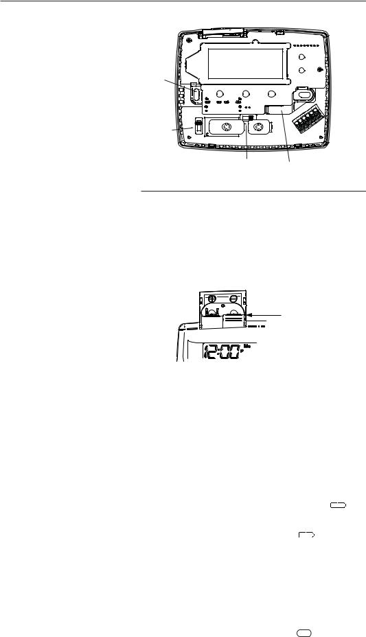
ATTACH THERMOSTAT BASE TO WALL
1.Remove the packing material from the thermostat. Gently pull the cover straight off the base. Forcing or prying on the thermostat will cause damage to the unit.
2.Place base over hole in wall and mark mounting hole locations on wall using base as a template (see Fig.1).
3.Move base out of the way. Drill mounting holes.
4.Push wires through opening in thermostat base.
5.Fasten base loosely to wall using two mounting screws. Place a level against bottom of base, adjust until level, and then tighten screws. (Leveling is for appearance only and will not affect thermostat operation.) If you are using existing mounting holes, or if holes drilled are too large and do not allow you to tighten base snugly, use plastic screw anchors to secure subbase.
6.Connect wires to terminals on base using appropriate wiring schematic (see figs. 2 through 4).
7.Push excess wire into wall and plug hole with a fire-resistant material (such as fiberglass insulation) to prevent drafts from affecting thermostat operation.
O/B TERMINAL SWITCH SELECTION
The O/B switch on this thermostat is factory set to the “O” position. This will accommodate the majority of heat pump applications, which require the changeover relay to be energized in COOL. If the thermostat you are replacing or the heat pump being installed with this thermostat requires a “B” terminal, to energize the changeover relay in HEAT, the O/B switch must be moved to the “B” position.
Battery
 Door
Door
Mounting
Hole
Mounting

 Hole
Hole
O/B
Switch
Gas/Elec |
Opening |
Switch |
for wires |
Figure 1. Thermostat Base
GAS / ELEC SWITCH
If your system is a heat pump, the GAS/ELEC Switch must be set to ELEC (see Fig. 1) If your system is a single stage, the switch must be set to GAS. The switch setting must agree with the system configuration selected in the configuration menu.
BATTERY LOCATION
“AA” Alkaline Batteries |
Two “AA” alkaline batteries are installed in your thermostat with a battery tag to prevent power drainage. Prior to use, open the battery door and remove the battery tag. To open, pull the battery door as shown by the arrow and lift open. The two “AA” batteries will operate all functions or maintain time and continuously display the temperature during a loss of AC power. Installed batteries will also allow programming prior to installation. To replace batteries, pull the battery door shown by the arrow and lift open. Using the polarity indicated inside the battery door, insert the batteries. To close the battery door, swing the door down while pulling in the direction of arrow. Once fully down, snap the door back into position.
Thermostat can be powered by system AC power or Battery. If  is displayed, the thermostat is battery powered.If


 is not displayed, thermostat is system powered with optional battery back-up. When battery power remaining is approximately half, the
 will be displayed. When “Change
 ” is displayed, install fresh “AA” alkaline batteries immediately. For best results, use new premium brand alkaline batteries such as Duracell® or Energizer®. We recommend replacing batteries every 2 years. If the home is going to be unoccupied for an extended period (over 3 months) and
 is displayed, the batteries should be replaced before leaving. When less than two months of battery life remain, the setpoint temperature will offset by 10 degrees (10 degrees cooler in Heat mode / 10 degrees warmer in Cool mode). If offset occurs, the normal setpoint can be manually reset with
 or
or  . Another offset will occur within two days if batteries are not replaced. To replace the batteries, set system to OFF.
2
INSTALLATION
ENERGY MANAGEMENT RECOVERY (EMR)
When the EMR feature is activated the thermostat’s microcomputer calculates the time it will take to change the room temperature to the next heat or cool program setting. Then the thermostat will start the system before the next programmed period so that the desired temperature is reached at or near the beginning of the period (the thermostat calculates 15 minutes for every 1°F temperature change). This feature provides better efficiency by allowing gradual temperature changes.
For example: The thermostat is programmed to provide an overnight heating temperature of 66°F, and during the next program period, beginning at 6:00 AM, the programmed temperature is 70°F. With EMR activated, the thermostat will
automatically start the heating system at 5:00 AM, so that the programmed temperature of 70°F is reached by about 6:00 AM.
If the overnight room temperature drops only to 68°F, the thermostat will start the system at 5:30 to reach the programmed temperature of 70°F at 6:00.
The thermostat is shipped with the EMR feature active, which means that the thermostat will start the heating system before the beginning of the next program period.
To deactivate the EMR function, see the Configuration menu on Page 5). The thermostat will then wait until the programmed time to start the system for a temperature change.
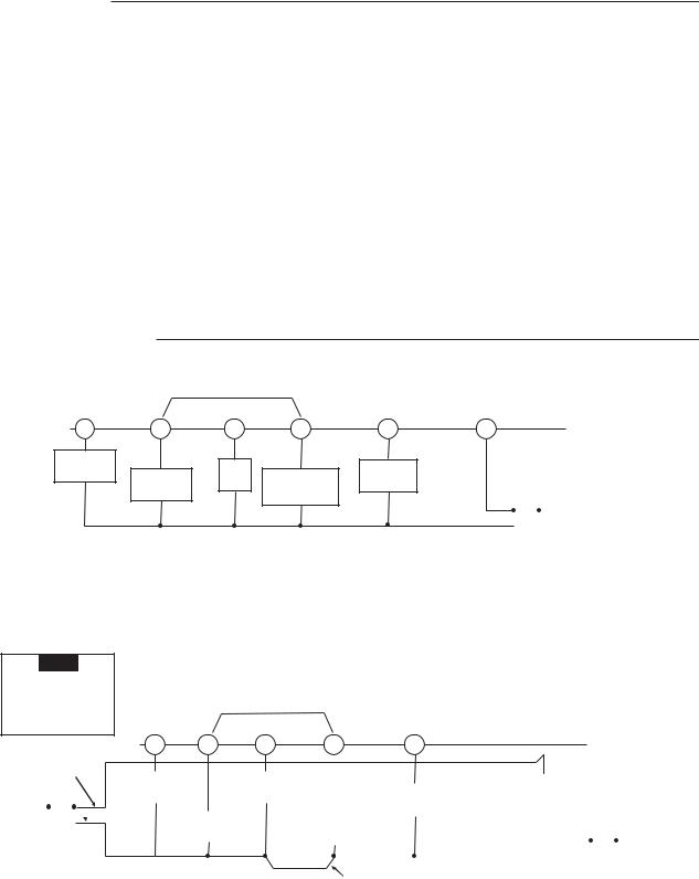
WIRING DIAGRAMS
Optional Jumper for
|
Single Stage Heat Pump |
|
||
O/B |
Y |
G |
W |
C |
Changeover |
|
Fan |
|
|
Relay* |
Compressor |
|
Optional |
|
Relay |
|
|||
|
Heat Relay |
|||
|
Contactor |
|
||
|
|
|
||
|
|
|
|
|
*Changeover Relay is energized in COOL when O/B switch is in the “O” position Changeover Relay is energized in HEAT when O/B switch is in the “B” position
THERMOSTAT
R
SYSTEM
24 VAC |
|
|
|
|
|
Hot |
|
|
|
|
|
120 VAC |
|
|
|
|
|
|
|
|
|
|
|
|
|
|
Neutral |
|
|
|
|
|
|
TRANSFORMER
(Class II Current Limited)
Figure 2. Typical wiring diagram for single transformer single stage systems
NOTE
If safety circuits are in only one of the systems, remove the transformer of the system with NO safety circuits.
Optional Jumper for
Single Stage Heat Pump
 THERMOSTAT
|
|
|
|
|
|
|
O/B |
Y |
|
G |
W |
|
|
C |
R |
|
|
|
|
|||||||||
CUT AND |
|
|
|
|
|
|
|
|
|
|
|
|
|
|
|
|
SYSTEM |
|
|
|
|
|||||||
TAPE OFF! |
|
|
|
|
|
|
|
|
|
|
|
|
|
|
|
|
|
|
|
|
|
|
||||||
|
|
|
|
|
|
|
Changeover |
|
|
Fan |
|
|
|
|
|
|
|
|
Limit or |
|
|
|
|
|
||||
|
|
|
|
|
|
Relay* |
|
|
Relay |
|
|
|
|
|
|
Optional |
|
Safety |
|
|
|
|
|
|||||
HOT |
|
|
|
|
|
|
|
|
|
|
|
|
|
|
|
|
|
|
|
|
||||||||
|
|
|
|
|
|
24 VAC |
|
|
|
|
|
|
|
|
|
|
|
|
|
Switches |
|
|
|
|
|
|||
120 VAC |
|
|
|
|
|
|
Compressor |
|
|
|
Heat Relay |
|
|
|
|
|
|
|
|
|
|
|
|
|||||
|
|
|
|
|
|
|
|
|
|
|
|
|
|
|
|
|
|
|
|
|
|
|
||||||
|
|
|
|
|
|
|
|
|
Contactor |
|
|
|
|
|
|
|
|
|
|
|
|
|
|
Hot |
||||
NEUTRAL |
|
|
|
|
|
|
|
|
|
|
|
|
|
|
|
|
|
|
|
|
|
|
|
|
||||
|
|
|
|
|
|
|
|
|
|
|
|
|
|
|
|
|
|
|
|
|
||||||||
|
|
|
|
|
|
|
|
|
|
|
|
|
|
|
|
|
|
|
|
|
|
|
|
|
|
|
|
|
|
|
|
|
|
|
|
|
|
|
|
|
|
|
|
|
|
|
|
|
|
24 VAC |
|
|
|
|
|
120 VAC |
|
|
|
|
|
|
|
|
|
|
|
|
|
|
|
|
|
|
|
|
|
|
|
|
|
|
|
|||
|
|
|
|
|
|
|
|
|
|
|
|
|
|
|
|
TWO COMMONS MUST |
|
|
|
|
|
|
|
|
Neutral |
|||
|
|
|
|
|
|
|
|
|
|
|
|
|
|
|
|
|
|
|
|
|
|
|
|
|||||
|
|
|
|
|
|
|
|
|
|
|
|
|
|
|
|
|
|
|
|
|
|
|
|
|
||||
* Changeover Relay is energized in COOL when O/B switch is in the “O” position |
|
|
|
|
TRANSFORMER |
|||||||||||||||||||||||
|
|
BE JUMPERED TOGETHER! |
|
|
||||||||||||||||||||||||
|
|
|
(Class II Current Limited) |
|||||||||||||||||||||||||
Changeover Relay is energized in HEAT when O/B switch is in the “B” position |
|
|
|
|
|
|
|
|||||||||||||||||||||
Figure 3. Typical wiring diagram for two transformer single stage systems with NO safety circuits
3

WIRING DIAGRAMS
|
|
|
|
|
|
|
|
|
|
|
|
|
|
|
|
|
|
|
|
|
|
|
|
|
NOTE |
|
|
|
|
|
|
|
|
|
|
||||
|
|
|
|
|
|
|
|
|
|
|
|
|
|
|
|
Polarity must be observed. If the HOT side of the |
|
||||||||||||||||||||||
|
|
|
|
|
|
|
|
|
|
|
|
|
|
|
|
second transformer is jumpered to the COMMON side |
|
||||||||||||||||||||||
|
|
Optional Jumper for |
|
|
|
|
|
|
|
|
|
of the first transformer a short will be made. Damage |
|
||||||||||||||||||||||||||
|
|
|
|
|
|
|
|
|
|
|
to equipment will occur when power is restored. |
|
|||||||||||||||||||||||||||
|
|
Single Stage Heat Pump |
|
|
|
|
|
|
|
|
|
||||||||||||||||||||||||||||
|
|
|
|
|
|
|
|
|
|
|
|
|
|
|
|
|
|
|
|
|
|
|
|
|
|
|
|
|
|
|
|
|
|||||||
|
|
|
|
|
|
|
|
|
|
|
|
|
|
|
|
|
|
|
|
|
THERMOSTAT |
|
|
|
|
|
|
|
|
|
|
|
|||||||
O/B |
|
Y |
|
G |
W |
|
|
C |
R |
|
|
|
SYSTEM |
|
|
|
|
|
|
|
|
|
|
|
|
||||||||||||||
|
|
|
|
|
|
|
|
|
|
|
|
|
|
|
|
|
|
|
|
|
|
|
|
|
|
Limit or |
|
|
|
|
|
|
|||||||
|
|
|
|
|
|
|
|
|
|
|
|
|
|
|
|
|
|
|
|
|
|
|
|
|
|
|
|
|
|
|
|
|
|
|
|
|
|
||
|
|
|
|
|
|
|
|
|
|
|
|
|
|
|
|
Limit or |
|
|
|
|
|
|
|
|
|
|
|
|
|
|
Safety |
|
HOT |
||||||
|
|
|
|
|
|
|
|
|
|
|
|
|
|
|
|
Safety |
|
24 VAC |
|
|
|
|
|
120 VAC |
Switches |
|
|
|
|
|
|
||||||||
|
|
|
|
|
|
|
|
|
|
|
|
|
|
|
|
Switches |
|
|
|
|
|
|
|
|
|
|
|
|
|
|
|||||||||
Changeover |
|
|
Fan |
|
|
|
|
|
Optional |
|
|
|
|
|
|
|
|
|
|
|
|
|
|
|
|
|
|
|
|
|
|
NEUTRAL |
|||||||
|
|
|
|
|
|
|
|
|
|
|
|
|
|
|
|
|
|
|
|
|
|
|
|
|
|
|
|
|
|||||||||||
Relay* |
|
|
|
Relay |
|
|
|
|
|
|
|
|
|
|
|
24 VAC |
|
|
|
|
|
|
|
|
|
|
|
|
|
|
|
|
|
|
|
|
|
||
|
|
|
|
|
|
|
|
|
|
|
|
|
|
|
|
|
|
Auxiliary |
|
|
|
|
|
|
|
|
|
|
|
|
|||||||||
|
|
|
|
|
|
|
|
|
|
|
|
|
|
|
|
ACCESSORY |
|
|
Heating |
|
|
|
|
|
NOTE |
|
|||||||||||||
|
Compressor |
|
|
|
|
Heat |
|
|
|
|
|
|
|
|
RELAY N.O. |
|
Transformer |
|
The |
|
accessory relay scheme |
||||||||||||||||||
|
|
|
|
|
|
|
|
|
|
|
|
||||||||||||||||||||||||||||
|
|
Contactor |
|
|
|
|
Relay |
|
|
|
|
|
|
|
|
CONTACT |
|
|
(Class II |
|
is |
required |
when safety |
||||||||||||||||
|
|
|
|
|
|
|
|
|
|
|
|
|
|
|
|
|
|
|
|
Current Limited) |
|||||||||||||||||||
|
|
|
|
|
|
|
|
|
|
|
|
|
|
|
|
COMMON |
|
circuits exist in both systems. |
|||||||||||||||||||||
|
|
|
|
|
|
|
|
|
|
|
|
|
|
|
|
||||||||||||||||||||||||
|
|
|
|
|
|
|
|
|
|
|
|
|
|
|
|
|
|
|
|
|
|
|
|
||||||||||||||||
|
|
|
|
|
|
|
|
|
|
|
|
|
|
|
|
|
|
|
|
|
|
|
|
|
|
|
|
|
|
|
|
|
|
|
|||||
|
|
|
|
|
|
|
|
|
|
|
|
|
|
|
|
|
|
|
|
|
|
|
|
|
|
|
|
|
|
|
|
|
|
|
|
|
|
|
|
|
|
|
|
|
|
|
|
TWO COMMONS MUST |
|
|
Limit or |
|
|
|
|
|
|
|
|
|
|
|
Limit or |
|
|
|
|
|
|
|
|||||||||
|
|
|
|
|
|
|
|
BE JUMPERED TOGETHER! |
|
|
Safety |
|
|
|
|
|
|
|
|
|
|
|
|
Safety |
HOT |
||||||||||||||
|
|
|
|
|
|
|
|
|
|
|
COMMON |
|
|
Switches |
24 VAC |
|
|
|
|
120 VAC |
Switches |
||||||||||||||||||
|
|
|
|
|
|
|
|
|
|
|
|
|
|
|
|
|
|
|
|
|
|
|
|
|
|
|
|
|
|
|
|||||||||
|
|
|
|
|
|
|
|
|
|
|
|
|
|
|
|
|
|
|
|
|
|
|
|
|
|
|
|
|
|
|
|||||||||
* Changeover Relay is energized in COOL when O/B switch is in the “O” position |
|
|
|
|
|
|
|
|
|
|
|
|
|
|
|
|
|
|
|
|
NEUTRAL |
||||||||||||||||||
|
|
|
|
|
|
|
|
|
|
|
|
|
|
|
|
|
|
|
|||||||||||||||||||||
|
|
|
|
|
|
|
|
|
|
|
|
|
|
|
|
|
|
|
|
|
|
|
|
|
|
|
|
||||||||||||
|
|
|
|
|
Heat Pump Transformer |
|
|
|
|
|
|
|
|
|
|
|
|
||||||||||||||||||||||
Changeover Relay is energized in HEAT when O/B switch is in the “B” position |
|
|
|
|
|
|
|
|
|
|
|
|
|
|
|
|
|
||||||||||||||||||||||
|
|
|
|
|
|
|
|
|
|
|
|
|
|
|
|
|
(Class II Current Limited) |
|
|
|
|
|
|
|
|
|
|
|
|||||||||||
Figure 4. Typical wiring diagram for two transformer single stage systems with safety circuits in BOTH systems
THERMOSTAT QUICK REFERENCE
Before you begin programming your thermostat, you should be familiar with its features and with the display and the location and operation of the thermostat buttons and switches (see fig. 5). Your thermostat consists of two parts: the thermostat cover and the base. To remove the cover, pull it straight out from the base. To replace the cover, line up the cover with the base and press until the cover snaps onto the base.
The Thermostat Buttons and Switches
1Raises temperature setting.
2Lowers temperature setting.
3TIME button.
4SYSTEM switch (COOL, OFF, HEAT, EMER).
5PRGM (program) button.
6FAN switch (ON, AUTO).
7RUN/HOLD (program) button.
The Display
8Indicates days of the week.
9Indicates setpoint temperature. This is blank when system switch is in the OFF position. Setpoint temperature is displayed (flashing) if the thermostat is in lockout mode to prevent the compressor from cycling too quickly.
10“Save” indicates the Cool Savings feature is enabled in the configuration menu. “Save” (flashing) indicates Cool Savings feature is active.
11Flame icon ( ) is displayed when the SYSTEM switch is in the HEAT position. Flame icon (
 ) is displayed flashing when thermostat is calling for heat. Snowflake icon (
 ) is displayed (non-flashing) when the SYSTEM switch is in the COOL position. Snowflake icon (
 ) is displayed (flashing) if the thermostat is calling for cool.
12Displays current temperature.
13“Service” indicates a diagnostic fault in the heating/cooling system. It does not indicate a fault in the thermostat.
14“Change Filter” is displayed when the system has run for the programmed filter time period as a reminder to change or clean your air filter.
15 “ |
|
|
|
|
|
|
|
” indicates power level of batteries. “Change |
|
|
|
” |
|
|
|
|
|
|
|
|
|
|
|||
indicates batteries should be replaced. |
|
|
|
|
||||||||
16Indicates time.
17“A” “P” indicates time as Morning (A) Evening (P).
18“Temp Hold”indicates temporary hold or “Hold” indicates hold mode.
Figure 5. Thermostat display, buttons, and switches
1
2
SYSTEM
3 |
4 |
5 |
6 |
7 |
|
|
17 |
18 |
|
16 |
|
|
|
8 |
|
|
|
|
|
|
|
|
|
9 |
15 |
|
|
|
|
|
|
|
|
10 |
14 |
|
13 |
12 |
11 |
4
 Loading...