


|
1E30(W)/1F30(W) |
|
WHITE-RODGERS |
Non-Anticipated |
|
Millivolt Room Thermostat |
||
|
||
|
INSTALLATION INSTRUCTIONS |
|
|
|
Operator: Save these instructions for future use!
FAILURE TO READ AND FOLLOW ALL INSTRUCTIONS CAREFULLY BEFORE INSTALLING OR OPERATING THIS CONTROL COULD CAUSE PERSONAL INJURY AND/OR PROPERTY DAMAGE.
DESCRIPTION
These low voltage thermostats are specially designed for use on self-generating systems. They are non-antici- pated, enabling them to be used on self-generated systems having pilot generator outputs from 250 to 750 millivolts.
1F30
1E30
If in doubt about whether your wiring is millivolt, line, or low voltage, have it inspected by a qualified heating and air conditioning contractor, electrician, or someone familiar with basic electricity and wiring.
Do not exceed the specification ratings.
All wiring must conform to local and national electrical codes and ordinances.
CONTENTS |
|
Description .......................................................... |
1 |
Precautions ......................................................... |
1 |
Specifications ...................................................... |
2 |
Installation ........................................................... |
2 |
Select Thermostat Location |
|
Route Wires to Location |
|
Attach Thermostat to Wall |
|
Operation & Maintenance ................................... |
3 |
Calibrating Thermometer |
|
Calibrating Thermostat |
|
PRECAUTIONS
This control is a precision instrument, and should be handled carefully. Rough handling or distorting components could cause the control to malfunction.
! CAUTION
To prevent electrical shock and/or equipment damage, disconnect electric power to system, at main fuse or circuit breaker box, until installation is complete.
Do not short out terminals on gas valve or primary control to test. Short or incorrect wiring will burn out heat anticipator and could cause personal injury and/or property damage.
!WARNING
Do not use on circuits exceeding 750 millivolts. Higher voltage will damage control and could cause shock or fire hazard.
ATTENTION!
This product contains mercury. There will not be any exposure to mercury under normal conditions of use. This product may replace a unit which contains mercury. Do not open mercury cells. If a cell becomes damaged, do not touch any spilled mercury. Wearing non-absorbent gloves, take up the spilled mercury with sand or other absorbent material and place into a container which can be sealed. If a cell becomes damaged, the unit should be discarded. Mercury must not be discarded in household trash. When this unit or the unit it is replacing is to be discarded, place in a suitable container and return to us at WHITE-RODGERS.
|
|
|
|
|
|
WHITE-RODGERS DIVISION |
PART NO. 37-5583A |
|
|
|
|
|
|
EMERSON ELECTRIC CO. |
Replaces 37-9587C |
|
|
|
|
|
|
||
|
|
|
|
|
|
9797 REAVIS RD., ST. LOUIS, MO. 63123 |
|
|
|
|
|
|
|
(314) 577-1300, Fax (314) 577-1517 |
9531 |
|
|
|
|
|
|
||
|
|
|
|
|
|
Printed in U.S.A. |
|
|
|
|
|
|
|
9999 HWY. 48, MARKHAM, ONT. L3P 3J3 |
|
|
|
|
|
|
|
(905) 475-4653, FAX (905) 475-4625 |
|
|
|
|
|
|
|
|
|
|
|
|
|
|
|
|
R
SPECIFICATIONS
ELECTRICAL DATA |
THERMAL DATA: |
Switch Rating: 250 to 750 millivolt DC 0.1 Amps |
Temperature Range: 10° to 32°C (50° to 90°F) |
|
Differential: 1.7°C (3°F) |
Switch Action: SPST - Sealed mercury switch |
|
INSTALLATION
SELECT THERMOSTAT LOCATION
Proper location insures that the thermostat will provide a comfortable home temperature. Observe the following general rules when selecting a location:
1.Locate thermostat about 5 ft. above the floor.
2.Install thermostat on a partitioning wall, not on an outside wall.
3.Never expose thermostat to direct light from lamps, sun, fireplaces or any temperature radiating equipment.
4.Avoid locations close to windows, adjoining outside walls, or doors that lead outside.
5.Avoid locations close to air registers or in the direct path of air from them.
6.Make sure there are no pipes or duct work in that part of the wall chosen for the thermostat location.
7.Never locate thermostat in a room that is warmer or cooler than the rest of the home, such as the kitchen.
8.Avoid locations with poor air circulation, such as behind doors or in alcoves.
9.The living or dining room is normally a good location, provided there is no cooking range or refrigerator on opposite side of wall.
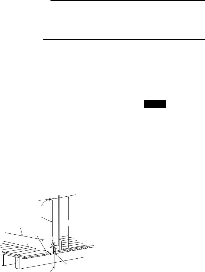
1/2" HOLE FOR
THERMOSTAT WIRE
STOUT CORD WITH 6"
CHAIN ATTACHED
APPROXIMATELY
BASEBOARD 5 FEET
STRIP MOLDING
1/4" GUIDE HOLE FOR SIGHTING
QUARTER ROUND
REMOVED
3/4" HOLE IN FLOOR OF PARTITION
HOOKED WIRE FOR SNAGGING CHAIN
Figure 1. Routing Thermostat Wires
ROUTE WIRES TO LOCATION
1.If an old thermostat is being replaced and is in a satisfactory location, and the wiring appears to be in good condition, use existing wiring. If in doubt, rewire.
2.If a new location is chosen or if this is a new installation, thermostat wire must first be run to the location selected. All wiring must conform with local and national electrical codes and ordinances.
NOTE
Because of the small amount of power available on selfgenerating systems, the gas valve may not operate if there is too much resistance in the circuit. Therefore, choose a location that does not require any more wire than the recommended lengths shown in the Thermostat
Wire Length Table.
THERMOSTAT WIRE LENGTH TABLE
Solid |
Max. Length |
Max. Combined Length |
Wire Sizes |
(2-wire cable) |
(2 single wires) |
|
|
|
No. 18 |
30 ft. |
60 ft. |
No. 16 |
50 ft. |
100 ft. |
No. 14 |
80 ft. |
160 ft. |
3.Probe for obstructions in partition before drilling 1⁄2” hole in wall at selected location. Take up quarter round and drill a small guide hole for sighting (see Fig. 1). From basement, drill 3⁄4” hole in partition floor next to guide hole. In houses without basements, drill 1⁄2” hole through ceiling and into partition from above (see Fig. 1).
4.Through this hole drop a light chain, or 6” chain attached to a strong cord. Snag cord in basement with hooked wire. In houses without basements, drop cord through hole in ceiling and down partitioning; snag cord at the thermostat location.
5.Attach thermostat wire to cord and pull wire through hole in wall so that 6” of wire protrudes.
2

! CAUTION
To prevent electrical shock and/or equipment damage, disconnect electric power to system, at main fuse or circuit breaker box, until installation is complete.
NOTE
This typical wiring diagram shows only terminal identification and wiring hook-up. Always refer to the wiring instructions provided by the equipment manufacturer for system hook-up.
All wiring should be installed according to local and national electrical codes and ordinances.
ATTACHING THERMOSTAT
1.Remove cover from thermostat by gripping the base in one hand. Use the other hand to pull gently at the top or bottom of the cover.
2.Carefully remove the shipping protective packing from the switch.
3.Pull wires through the opening in the thermostat base and connect wires beneath the terminal screws (see Fig. 2 & 3).
5.Position thermostat base over hole in wall and mark mounting hole location on wall.
6.Drill mounting hole.
7.Fasten base loosely to wall using mounting screws. Place a level against the top of the thermostat base, adjust until level, and tighten mounting screws to secure base. If holes in wall are too large and do not allow you to tighten the mounting screws securely, use plastic expansion plugs.
8.Snap cover on the thermostat base and set temperature lever to desired setpoint.
9.Turn on electrical power to system.
|
Thermostat |
|
Switch |
Terminal |
Heat |
Screws |
THERMOSTAT |
|
|
Power Generator |
SYSTEM |
|
|
Pilot Flame |
|
|
Heating |
|
System |
4. Push excess wiring back into wall and plug hole with
fire resistant material (such as fiberglass insulation) to Figure 2. Typical Wiring Diagram prevent drafts from affecting thermostat operation.
Terminal
Screws
COVER |
THERMOSTAT |
|
|
|
BASE |
Figure 3. Parts of Thermostat |
|
THERMOSTAT |
|
COVER |
BASE |
Mounting screws |
|
|
OPERATION & MAINTENANCE
CALIBRATING THERMOMETER ON
THERMOSTAT COVER
If thermometer reading on cover does not match the thermostat:
1.Remove thermostat cover.
2.Set cover on table near an accurate thermometer.
3.Allow at least 10 minutes for thermometer to sense room temperature.
4.If the thermometer readings are the same, replace thermostat cover.
5.If the thermometer readings are different, insert a small screwdriver blade into the thermometer shaft in the back of the cover. Adjust until the cover thermometer matches the other thermometer (See Fig. 4).
6.Replace thermostat cover.
Thermometer
Adjustment
Back Side of
Thermostat Cover
Figure 4. Calibrating Thermostat Thermometer
3
 Loading...