


1311
Printed in U.S.A.
Operator: Save these instructions for future use!
FAILURE TO READ AND FOLLOW ALL INSTRUCTIONS CAREFULLY BEFORE
INSTALLING OR OPERATING THIS CONTROL COULD CAUSE PERSONAL
INJURY AND/OR PROPERTY DAMAGE.
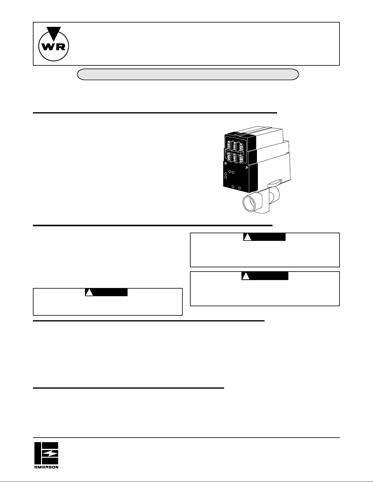
DESCRIPTION
These water valves provide a low cost system of zoned tem-
perature control wherever hot water is the heating medium. In
new construction, the heating piping system can be laid out to
produce any number of independent temperature controlled
zones by use of these valves.
In existing buildings, a variety of zone heating combinations can
be obtained, depending on the particular piping lay-outs. Each
zone requires one water valve and one thermostat, but only
one circulator is required for the entire system. New con-
struction properly piped, will not require flow control valves,
since the water valve itself performs this function.
Existing construction, where flow control valves have been
installed, will operate quite satisfactorily without removing the
existing flow control valves.
PRECAUTIONS
This zone valve motor is intended for use with a low voltage
system; do not use this zone valve with a millivolt or line voltage
system. If in doubt about whether your wiring is millivolt, line or
low voltage, have it inspected by a qualified heating contractor
or electrician.
Do not exceed the specification ratings.
All wiring must conform to local and national electrical codes and
ordinances.
To prevent electrical shock and/or equipment damage,
disconnect electric power to system at main fuse or
circuit breaker box until installation is complete.
To prevent injuries from scalding always drain system
before unlatching valve assembly from body.
INST ALLA TION INSTRUCTIONS
TYPE 1311
HYDRONIC ZONE VALVES
(3 WIRE)
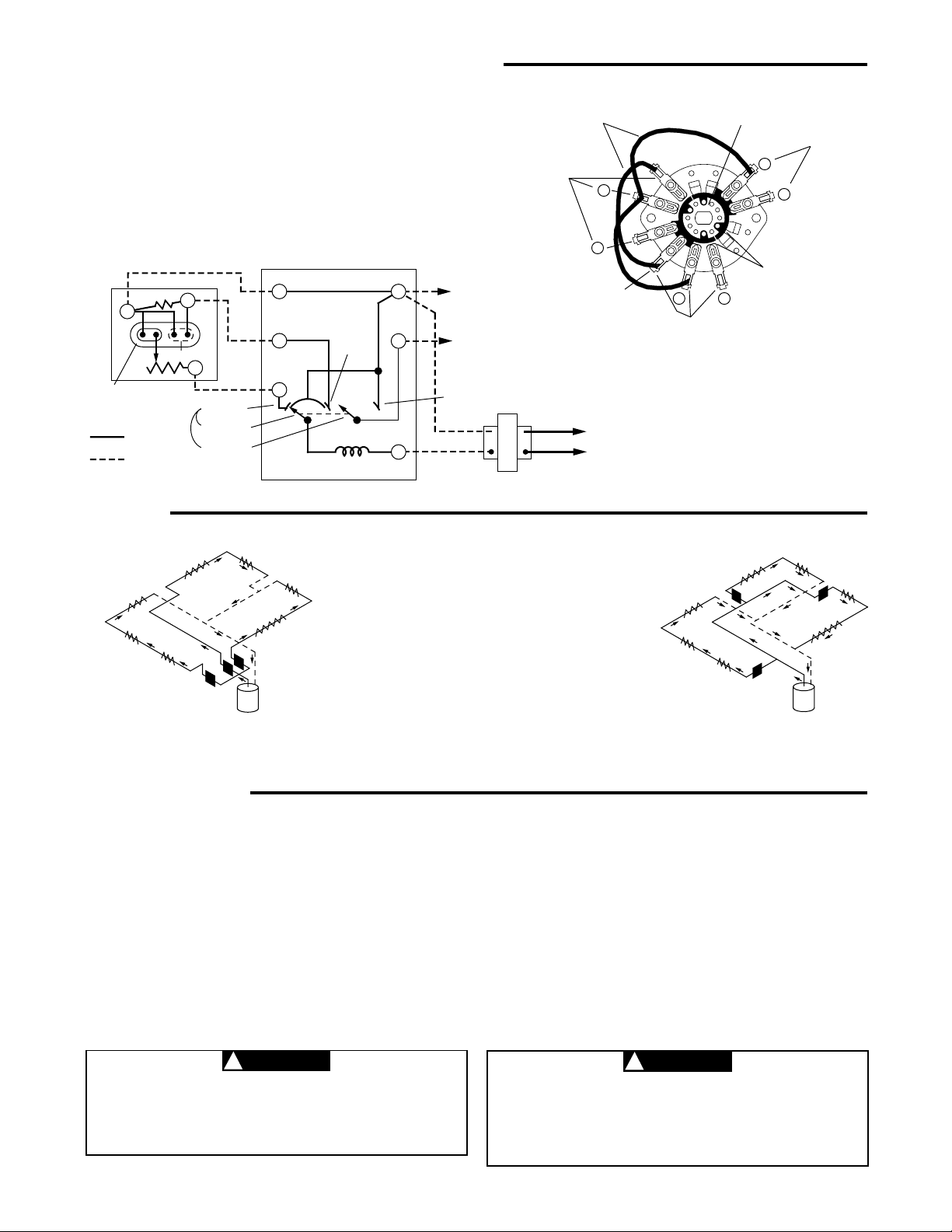
The schematic shows the valve in the closed position. As the
thermostat calls for heat, the valve motor is energized and
begins to open the valve. Soon thereafter side “A” of motor
switch makes with the holding contacts. This contact provides a
holding circuit to prevent the valve from stopping part way
through its cycle if the thermostat is changed to the satisfied
Do not use on circuits exceeding specified voltages.
Higher voltages will damage control and could cause
shock or fire hazard.
SPECIFICATIONS
All guarantees are void if these specifications are exceeded.
Maximum water temperature: 240°F (115°C)
Maximum system pressure: 50 PSI
Differential across valve: 15 PSI
Electrical Rating:
Valve Motor: 25 VAC (.40 Amp.)
Auxiliary Contacts: Do not exceed 2.0 Amp. at 25 VAC
(Terminals 2 and 3)
Timing: Approximately 45 seconds from full open to full close
or full close to full open.
Friction loss equivalents:
3/4" valve – 2-1/2 ft. copper tubing
1" valves – 4 ft. copper tubing
1-1/4" valves – 7 ft. copper tubing
PRINCIPLE OF OPERATION
position. Just before the valve reaches the full-open position,
side “B” of motor switch closes (providing a low voltage auxiliary
circuit for starting burner and/or circulator). The motor stops with
the valve in the open position when side “A” of motor switch
breaks the holding contact. (Completing a circuit through con-
tact “6” and the thermostat anticipator.)
PART NO. 37-5421B
Replaces 37-5421A
9812
WHITE-RODGERS DIVISION
EMERSON ELECTRIC CO.
9797 REAVIS RD., ST. LOUIS, MO. 63123
(314) 577-1300, Fax (314) 577-1517
9999 HWY. 48, MARKHAM, ONT. L3P 3J3
(905) 475-4653, FAX (905) 475-4625
CAUTION
!
CAUTION
!
WARNING
!
WHITE-RODGERS
2
PRINCIPLE OF OPERATION (Continued)
When thermostat is satisfied, the valve motor is again ener-
gized. Just after the valve starts to close, side “A” of motor switch
makes with holding contact providing a holding circuit. The side
“B” of motor switch opens (breaking auxiliary circuit), and side
“A” of motor switch makes with contact “4” then breaks the
holding circuit stopping the valve in the closed position. (Fig. 2)
The contact arrangement is constructed so that when the shaft
of the motor revolves 90° a new set of stationary contacts makes
while the old set breaks. (Fig. 1)
NOTE: To check motor operation without thermostat
connected, jumper 4 to 5 to open valve; jumper
5 to 6 to close valve.
MOTOR SHAFT:
Revolves in 90° intervals
with each thermostat cycle.
STATIONARY CONTACTS
(TERMINALS 2 & 3)
STATIONARY CONTACTS
(TERMINALS 2 , 6 & COM.)
JUMPER WIRES
NOTE: INTERNAL PARTS AND
WIRING OF WATER VALVE.
COMMON
2
6
4
3
2
2
ROTATING BOARDS:
Each Board makes/breaks
1 set of contacts with each
90° revolution of motor
shaft on thermostat
demand.
▼
▼
▼
▼
▼
▼
▼
▼
▼
▼
▼
▼
▼
▼
▼
Use only silicone grease, water, or soap suds on O-ring
or Valve Body to facilitate assembly. Use of vaseline or
any petroleum grease or oil will cause O-ring to deterio-
rate.
Be sure that bayonet lock securely latches mounting
plate to body. Failure to do so could allow valve head
to separate from body and result in scalding injuries
and/or water damage.
1. Remove body assembly only from shipping carton. Valve
head and stem should be left in carton at this time for
protective purposes. Do not assemble head to body before
attaching body into line.
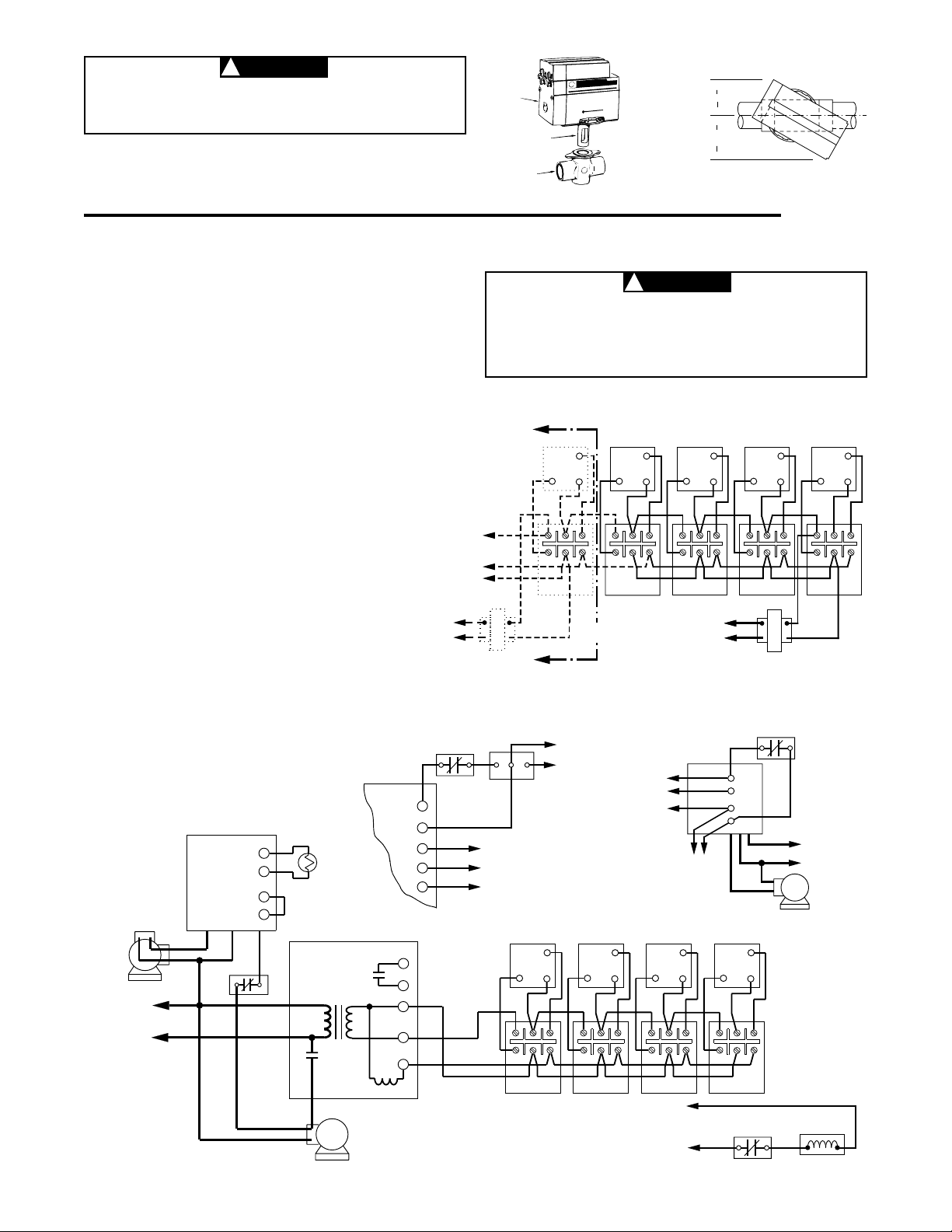
2. Mount the valve body in the line in any desired position
except upside down. CAUTION: Provide the necessary
clearances for turning valve head sideways when assem-
bling it to valve body (see fig. 3). Note that terminal end of
valve head requires more clearance.
3. Be sure that any excess solder, flux, or other foreign matter
is thoroughly removed from the valve bore.
4. With valve body mounted in the line, remove the head
assembly from the carton, and carefully wipe stem with a soft
cloth to remove any dust or grit.
5. The valve head may now be assembled to the valve body.
With valve head positioned as shown in figure 5, insert valve
stem into valve bore, push downward, and turn valve head
until it locks to valve body.
6. Support piping with a pipe hanger on each side of valve. The
valve is now ready to be wired.
ALL GUARANTEES ARE VOID IF THE VALVE IS NOT ASSEMBLED ACCORDING TO THESE INSTRUCTIONS.
INSTALLATION
The two most commonly used piping systems are
shown below. Plan 1 is popular for new installations,
while plan 2 is frequently used for converting two-pipe
systems.
This valve does not seal completely. A small amount of
leakage through valve is permitted. The amount de-
pends on valve size and pressure differential across
closed valve. Do not use if your application requires
complete seal off. Maximum leakage at rated differen-
tial is two, four or six gal. per hour for 3/4", 1" or 1-1/4"
valves, respectively.
729
PLAN 1
Water valves installed at the boiler
header to provide a separate sup-
ply to each zone.
PLAN 2
A common main supplies all
zones, with a water valve installed
on the riser to each zone.
Fig. 3
Fig. 4
PIPING
▼
TRANSFORMER
INTERNAL
WIRING
EXTERNAL
WIRING
MOTOR
ANTIC.
SATISFIED
CALL FOR
HEAT
HOLDING
CONTACT
SIDE “A”
OPEN
POSITION
WATER VALVE
THERMOSTAT
TO AUXILIARY CIRCUIT
FOR OPERATING BURNER
AND/OR CIRCULATOR.
(NOTE: IF SAME TRANS-
FORMER POWERS BOTH
THE AUXILIARY CIRCUIT
AND THE WATER VALVE,
CONNECT AUXILIARY CIR-
CUIT TO TERMINALS 1 AND
3 INSTEAD OF 2 AND 3.)
SIDE “B”
OPEN
POSITION
2
3
6
5
4
LINE
▼
▼
▼
▼
▼
▼
▼
CLOSED
POSITION
SIDE “A” OF
MOTOR SWITCH
SIDE “B” OF
MOTOR SWITCH
▼
1
4
6
5
STATIONARY CONTACTS
(TERMINALS 2, 4 & COM.)
(Valve is shown in the open position)
Fig. 1
Fig. 2
SCHEMATIC OF VALVE
CAUTION
!
CAUTION
!
3
F
F
T
T
V1
V2
1
2
3
4
56
4
56
4
56
4
56
1
2
3
452
6
1
2
3
452
6 1
2
3
452
6 1
2
3
452
6
To prevent injuries from scalding always drain system
before unlatching valve assembly from body.
▼
▼
▼
▼
2-3/4" MINIMUM
CLEARANCE
2" MINIMUM
CLEARANCE
VALVE
HEAD
STEM
BODY
Fig. 5
DIAGRAM FOR SYSTEMS WHERE BURNER AND
CIRCULATOR OPERATION IS INDEPENDENT OF
THERMOSTAT
Fig. 6 Using Type 1311 Zone Valve
T2
T1-V1
V2-L1
Z-L2
MUST BE N.E.C.
CLASS 1 WIRING
MUST BE
N.E.C. CLASS 1
WIRING
CIRCULATOR
MOTOR
1
2
3
{
TO ZONE
VALVES
TO 24 VOLT
GAS VALVE
YELLOW
HIGH LIMIT
TYPE 8A02A-1
CIRCULATOR MOTOR
HIGH LIMIT
RELAY CONTACTS
(24V OR 750 MV)
TRANSFORMER
RELAY COIL
WHITE
BLACK
WHITE
ORANGE
RELAY
CONTACTS
(LINE
VOLTAGE)
BURNER
MOTOR
IGNITION
TRANS.
TYPE 668 OIL
BURNER CONTROL
N
LINE
HOT
BLACK
TYPE 8A03A-2
ORANGE
V1
V2
TH
TH PG
PG
3
2
1
TYPE 8A03A-2
HIGH LIMIT
MUST BE N.E.C.
CLASS 1 WIRING
750 MV
GAS VALVE
1
2
3
}
TO ZONE VALVES
Alternate Wiring for using
750 Mv. Gas Valve
Alternate Connections
For Type 8A02A Relay
Fig. 7 Diagram
for Oil-fired
System using
8A03A-2
24 VAC
GAS VALVE
HIGH LIMIT
1
3
MUST BE N.E.C.
CLASS 1 WIRING
Fig. 7a Diagram for
Gas-Fired System
All wiring should be done according to local and national electrical codes
Do not attempt to wire two or more zone valves in
parallel to operate from a single thermostat. (If valves
are wired in parallel, the motors may run continuously,
due to feedback between the motor holding circuits.)
For best connections, use #18 Thermostat wire. #16 will also
work satisfactorily.
Make connections to screw terminals according to wiring dia-
gram.
NOTE: To check motor operation without thermostat con-
nected, jumper 4 to 5 to open valve; jumper 5 to 6 to close
valve.
If the boiler manufacturer recommends a wiring diagram, follow
his instructions. If none are available, the following diagrams
show suggested circuits for Type 1311 Water Valves in conjunc-
tion with other W-R controls.
A 40 VA transformer will handle up to four (4) water valves. A 20
VA transformer will handle up to two (2) water valves.
Clearances required for assembling valve head to valve body.
4
56
4
56
4
56
4
56
4
56
1
2
3
452
6
1
2
3
452
6
1
2
3
452
61
2
3
452
61
2
3
452
6
ADDITIONAL
ZONES
HOT
LINE
N
TRANSFORMER
DIAGRAM FOR SYSTEMS WHERE INTERNAL TRANSFORMER OF RELAY CONTROL SUPPLIES POWER
FOR ZONE VALVES
WIRING
TYPE 956
FLAME DETECTOR
HOT
LINE
N
750 MV
POWER
GENERATOR
CAUTION
!
CAUTION
!
 Loading...