


Whirlpool WHAB-6013, WHAF-0435AC, WHAB-6014, WHAB-6012, WHAB-6015 User Manual
...model / modelo |
model / modelo |
WHAF-0335AB |
WHAF-0435AC |
System tested and certified by NSF International against ANSI/NSF Standard 53 for Lead, Cyst and VOC Reduction (see the claims specified on the Performance Data Sheet) and Standard 42 for Chlorine, Taste and Odor Reduction.
Sistema verificado y certificado por el instituto NSF International según lo dispuesto por la norma ANSI/NSF 53 en lo que se refiere a la disminución de plomo, esporas y COV (ver lo dispuesto en la ficha técnica de rendimiento) y la norma 42 en lo que se refiere a la disminución de cloro, sabor y olor.
model / modelo |
model / modelo |
WHAB-6014 |
WHAB-6012 |
WHAB-6015 |
WHAB-6013 |
The WHAB faucet unit is tested and certified by NSF International against ANSI/NSF Standard 42 for material and structural integrity requirements only.
El grifo WHAB ha sido verificado y certificado por el instituto NSF International según lo establecido por la norma 42 NSI/NSF 42en lo que se refiere a la integridad estructural y de los materiales únicamente.
UNDER SINK
MODULAR
FILTRATION SYSTEM
Installation Instructions and
Use and Care Guide
For questions about features, operation/performance, parts, accessories or service, call: 1-866-363-9472.
Or visit our website at www.whirlpool.com
SISTEMA DE
PURIFICACIÓN
MODULAR
PARA INSTALAR BAJO FREGADEROS
Instrucciones de instalación y guía de usos y cuidados
Para mayor información sobre características, operación y funcionamiento, repuestos, accesorios o servicio técnico, comuníquese al 1-866-363-9472.
O visite nuestra página en Internet... www.whirlpool.com
Table of Contents/Índice......................................... |
2 |
8563999 / OEM030099-284

TABLE OF CONTENTS
INTRODUCTION TO ULTRAEASE™ UNDER SINK |
|
MODULAR FILTRATION SYSTEM.......................................... |
3 |
ASSISTANCE OR SERVICE....................................................... |
3 |
INSTALLATION REQUIREMENTS.............................................. |
3 |
Location Requirements............................................................. |
4 |
Water Supply Requirements.................................................... |
6 |
INSTALLATION INSTRUCTIONS................................................ |
7 |
Tools and Parts............................................................................ |
7 |
Install the Filterhead Valve and Filter Cartridge................ |
8 |
Install the faucet........................................................................ |
10 |
Connect faucet to filters.......................................................... |
11 |
FILTRATION SYSTEM ACCESSORIES.................................. |
12 |
FLUSHING THE FILTRATION SYSTEM................................ |
12 |
FLOW MONITOR.................................................................... |
12 |
FAUCET FEATURES (WHAB-6014, WHAB-6015)............. |
12 |
Vegetable sprayer...................................................................... |
12 |
FAUCET CARE (WHAB-6014, WHAB-6015)...................... |
12 |
Cleaning....................................................................................... |
12 |
BEFORE CALLING FOR SERVICE........................................ |
12 |
TROUBLESHOOTING............................................................. |
13 |
ULTRAEASE™ FILTRATION UNIT WARRANTY................... |
13 |
PERFORMANCE DATA SHEETS............................................ |
14 |
ÍNDICE
PRESENTACIÓN DEL SISTEMA DE PURIFICACIÓN |
|
MODULAR ULTRAEASE™ PARA INSTALAR |
|
BAJO FREGADEROS.............................................................. |
18 |
ASISTENCIA O SERVICIO TÉCNICO.................................... |
18 |
REQUISITOS PARA LA INSTALACIÓN.................................. |
19 |
Requisitos para la ubicación................................................. |
19 |
Requisitos del suministro de agua..................................... |
22 |
INSTRUCCIONES PARA LA INSTALACIÓN.......................... |
22 |
Herramientas y piezas............................................................ |
22 |
Instalación de la válvula de la cabeza del filtro y el |
|
cartucho que contiene el filtro............................................ |
24 |
Instalación del grifo................................................................ |
26 |
Conexión del grifo a los filtros............................................ |
27 |
ACCESORIOS PARA EL SISTEMA DE PURIFICACIÓN..... |
28 |
LIMPIEZA DEL SISTEMA DE PURIFICACIÓN................... |
28 |
MONITOR DE CIRCULACIÓN DE AGUA............................ |
28 |
CARACTERÍSTICAS DEL GRIFO |
|
(WHAB-6014, WHAB-6015)................................................ |
28 |
Rociador de legumbres.......................................................... |
28 |
CUIDADOS DEL GRIFO (WHAB-6014, WHAB-6015)..... |
28 |
Limpieza...................................................................................... |
28 |
ANTES DE LLAMAR AL SERVICIO TÉCNICO.................... |
29 |
GUÍA DE PROBLEMAS Y SOLUCIONES............................ |
29 |
GARANTÍA DE LA UNIDAD DE PURIFICACIÓN |
|
ULTRAEASE™.......................................................................... |
30 |
FICHAS TÉCNICAS DE RENDIMIENTO.............................. |
31 |
2
INTRODUCTION ULTRAEASE™ UNDER SINK
MODULAR FILTRATION SYSTEM
Welcome to a New Era in Home Water Filtration Systems.
Thank you for purchasing the UltraEase™ Modular filtration system, Whirlpool Brand's latest innovative under sink water filtration system. This system will provide you with many years of great-tasting water.
Whether from your town’s water treatment plant or decaying pipes in your home, sediment rust, sand, silt and iron can be present in your water. What’s more, chlorine, lead and cyst levels may further affect the quality of your water. Your new UltraEase™ easy to connect filters, effectively reduce these unwanted particles from your water supply more simply than ever.
The unit’s NSF-certified filter cartridges have been tested to process up to 1,200 gallons of water before any replacement is needed (approximately 6 to 12 months* depending on your water consumption and flow rate). See the last page for more details. Replacing a filter is an easy “lift ‘n’ snap” operation, complete with an automatic shut-off water valve. And should you decide to upgrade to a more comprehensive water filtration system, your UltraEase™ easy to connect Filter Unit’s modular design allows you to add on other components that filter chemicals for even better-tasting water. As an option, you can also add to your system the DirectChill™ and/or the DirectHot™ units.
* The contaminants or other substances removed or reduced by this water filter are not necessarily in all users' water. Filter life varies depending on local water conditions and the volume of water used. We recommend you change your filter every 12 months. However, it can be replaced earlier if there is a drop in pressure at the faucet or when the monitor indicates.
ASSISTANCE OR SERVICE
If you need assistance or service, first see “Troubleshooting” section. Additional help is available by calling 1-866-363-9472. Monday to Friday 8:00 a.m. - 6:00 p.m. (EST) or write:
Whirlpool Water Products P.O. Box 13150
Columbus, OH 43213-0150
Please include a daytime phone number in your correspondence.
For installation and service, call: 1-866-363-9472 or visit our website at www.whirlpool.com.
Keep this book and your sales slip together for future reference. You must provide proof of purchase or installation date for in-warranty service.
Write down the following information about your appliance to help you obtain assistance or service if you need it. You will need to know your complete model number. You can find this information on the packaging.
Dealer name _______________________________________________________________________________________________________
Address ___________________________________________________________________________________________________________
Phone number_________________________________ Model number_____________________________________________________
Purchase date______________________________________________________________________________________________________
INSTALLATION REQUIREMENTS
IMPORTANT:
Observe all governing codes and ordinances. Check location where the faucet will be installed. Make sure you have everything necessary for correct installation. It is the responsibility of the installer to comply with installation specifications and with state and local plumbing codes.
The faucet requires a 1-3\8’’ (3.5cm) diameter opening in the sink or countertop. The faucet can be installed in place of the sink spray hose. If faucet is not to be installed in sink spray hose opening, it is recommended that a qualified installer be contacted to drill a hole through your sink or countertop. Thickness of countertop at the hole must not exceed 1-3/4’’ (4.4cm).
Cold water supply connection must be available. See ‘’Water supply requirements’’, section. Water connections use easy to connect fittings which do not require sealing compounds to keep them from leaking.
3
Note:
On the easy to connect fittings the white collet represents “water in”. The blue collet represents “water out”.
Location Requirements
Filtration unit layouts
1
|
2 |
|
|
7 |
8 |
3 |
6 |
|
|
|
3
3
4
5
1
2
9
8
3 7
3
3
4
6
5
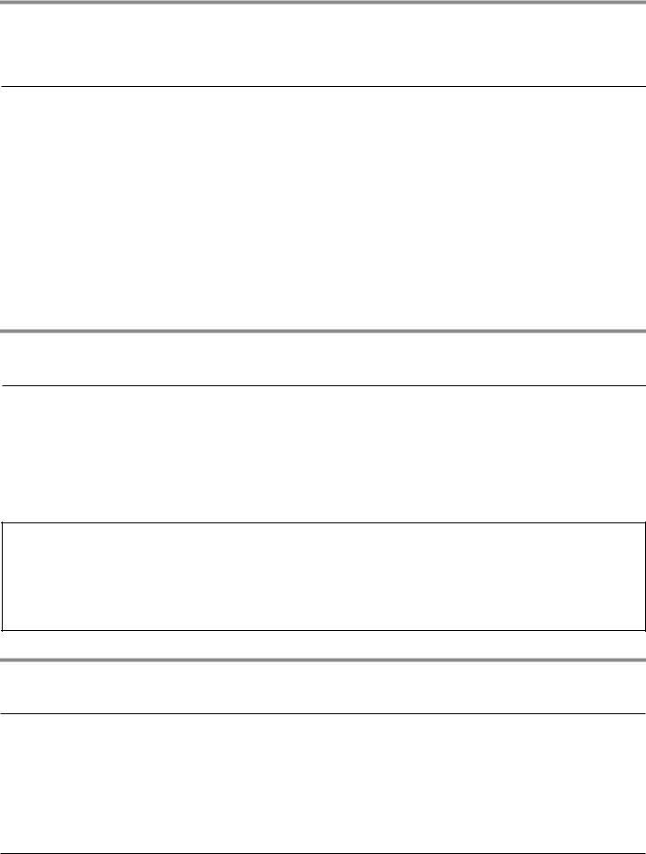
Layout 1
Installing UltraEase™ Dual stage water filtration Unit A+B (WHAF-0335AB), requires the Whirlpool™ UltraEase™ faucet (WHAB-6012 or 6013 or 6014 or 6015) sold separately.
If faucet is not to be installed in sink spray hose opening, cut 1-3/8” (3.5 cm) dia. sink or countertop cutout.
1-3/4” (4.4 cm) max. countertop or sink thickness.
1.Faucet installed in spray hose opening in sink (styles vary by model)
2.Cold water supply line
3.White tube included with faucet
4.“T” water line connector included with faucet
5.Flow monitor included with faucet
6.Wall mounting clips for tubing
7.White “water in” collet
8.Blue “water out” collet
Layout 2
Installing UltraEase™ Specialty water filtration Unit C (WHAF-0435AC sold separately), requires the UltraEase™ Dual stage water filtration Unit A+B (WHAF-0335AB) and Whirlpool™ UltraEase™ faucet (WHAB-6012 or 6013 or 6014 or 6015) sold separately.
1.Faucet installed in spray hose opening in sink (styles vary by model)
2.Cold water supply line
3.White tube included with faucet
4.“T” water line connector included with faucet
5.Specialty filtration sold separately
6.Flow monitor included with faucet
7.Wall mounting clips for tubing
8.White “water in” collet
9.Blue “water out” collet
4

1
|
2 |
|
|
|
|
8 |
|
|
9 |
|
|
|
11 |
|
|
|
3 |
7 |
|
|
6 |
|
|
10 |
|
14.75" |
|
3 |
(37.46 cm) |
||
|
|||
4 |
5 |
|
|
|
8.72" |
10.30" |
|
|
(22.14 cm) |
(26.16 cm) |
1
|
|
2 |
10 |
8 |
|
|
|
|
|||
|
12 |
|
9 |
|
|
|
|
3 |
|
7 |
|
|
|
|
|
||
|
|
|
6 |
12" |
|
|
|
|
|
(30.5 cm) |
|
11 |
|
|
|
|
|
|
|
|
8.50" |
7.375" |
|
|
|
|
(18.8 cm) |
||
4 |
5 |
3 |
(21.6 cm) |
||
|
|||||
|
|
|
|
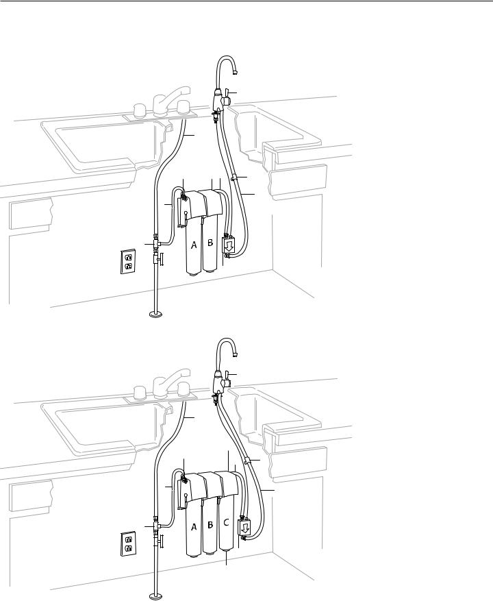
Layout 3
Adding the UltraEase™ DirectChill™ unit (WHAF-0115AG), requires the UltraEase™ Dual water filtration Unit A+B (WHAF-0335AB) and Whirlpool™ UltraEase™ faucet (WHAB-6012 or 6013 or 6014 or 6015) sold separately.
UltraEase™ Specialty water filtration Unit C (WHAF-0435AC) is optional in this layout (sold separately).
1.Faucet installed in spray hose opening in sink (styles vary by model)
2.Cold water supply line
3.White tube included with faucet
4.Specialty filtration sold separately
5.Flow monitor included with faucet
6.“T” water line connector included with faucet
7.DirectChill™ unit
8.Blue tube included with chiller
9.Wall mounting clips for tubing
10.White “water in” collet
11.Blue “water out” collet
Layout 4
Adding the UltraEase™ DirectHot™ unit (WHAF-0115AF), requires the UltraEase™ Dual water filtration Unit A+B (WHAF-0335AB).
IMPORTANT:
A Dual temperature faucet is included with the DirectHot™ unit. It does not require the faucet model WHAB-6012 or 6013 or 6014 or 6015.
UltraEase™ Specialty water filtration Unit C (WHAF-0435AC) is optional in this layout (sold separately).
1.Dual temperature faucet included with the DirectHot™ unit
2.Cold water supply line
3.White tube included with DirectHot™ unit
4.Specialty filtration sold separately
5.Flow monitor included DirectHot™ unit
6.“T” water line connector included with faucet
7.DirectHot™ unit
8.Yellow tubing
9.Red tubing
10.Wall mounting clips for tubing
11.White “water in” collet
12.Blue “water out” collet
5
|
|
1 |
|
2 |
|
|
10 |
|
12 |
11 |
9 |
|
|
 14
14
3
8
6
13
7
5
4
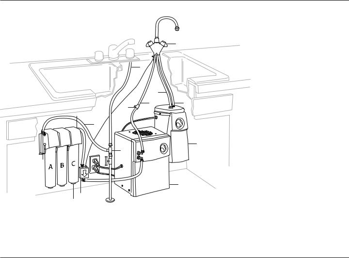
Layout 5
If you wish to add the UltraEase™ DirectHot™ unit (WHAF-0115AF) and the UltraEase™ DirectChill™ unit (WHAF-0115AG), it will require the UltraEase™ Dual water filtration Unit A+B (WHAF-0335AB).
IMPORTANT:
A Dual temperature faucet included with the Direct Hot unit. It does not require the faucet model WHAB-6012 or 6013 or 6014 or 6015. UltraEase™ Specialty water Filtration Unit C (WHAF-0435AC) is optional in this layout (sold separately).
1.Dual temperature faucet included with the DirectHot™ unit
2.Cold water supply line
3.White tubing with included DirectHot™ unit
4.Specialty filtration sold separately
5.Flow monitor included with DirectHot™ unit
6.“T” water line connector included with faucet
7.DirectChill™ unit
8.DirectHot™ unit
9.Yellow tubing
10.Red tubing
11.Blue tubing included with chiller
12.Wall mounting clips for tubing
13.White “water in” collet
14.Blue “water out” collet
Water Supply Requirements
If local codes permit, connect the UltraEase™ modular filtration system feed line to the cold water supply line with the ‘’T’’ connector (supplied with UltraEase™ faucets product number WHAB-6012, WHAB-6013, WHAB-6014, WHAB6015 and DirectHot™ unit WHAF-0115AF).
If you are using the UltraEase™ filtration unit, the Directchill™ unit and/or the DirectHot™* unit should be connected after the filtration unit.
IMPORTANT: If local codes do not permit the use of the ‘’T’’ connector, special feed valves can be obtained from your local plumbing supply distributor. Do not connect the filters to the hot water line. This will ruin the filters. The water pressure to the DirectChill™ unit or DirectHot™* unit should not drop below 30 psi (min.) nor rise above 100 psi (max.).
*Delineated that the DirectHot™ unit is not tested or certified by NSF International.
6
INSTALLATION INSTRUCTIONS
IMPORTANT:
Do not use with water that is microbiologically unsafe or of unknown quality without adequate disinfection before or after the system. Systems that are certified for cyst reduction may be used on disinfected water that may contain filterable cysts.
Tools and Parts
Tools Needed
Assemble the required tools and parts before starting installation. Read and follow the instructions provided with any tools listed here.
Pencil |
Measuring tape |
|
Phillips screwdriver |
Small level |
|
Drill with 1/16’’ drill bit |
1-3/8’’ hole saw |
|
Adjustable wrench |
Utility knife |
|
|
|
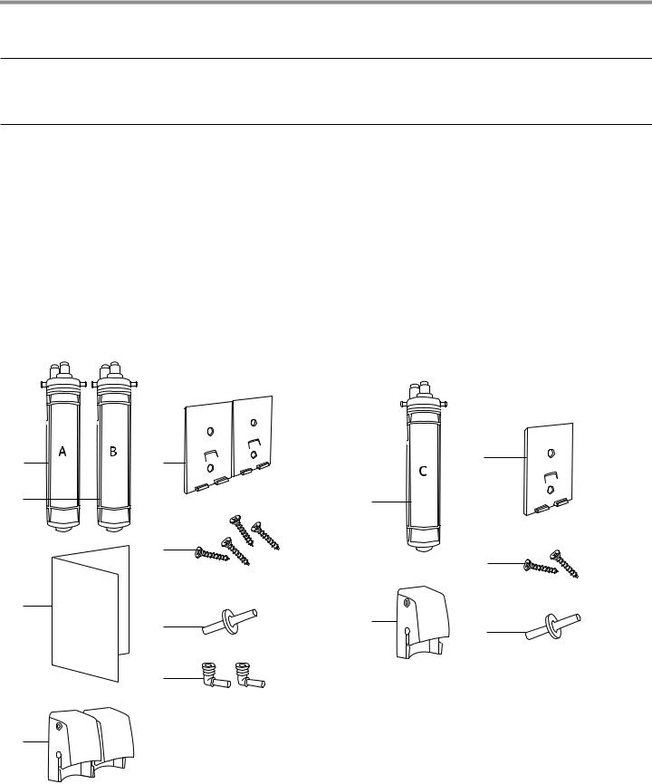
|
Dual stage water filtration system |
Additional filtration available |
|
(model WHAF-0335AB) |
Specialty water filtration system |
|
Parts Supplied |
(model WHAF-0435AC) |
|
|
|
Parts Supplied |
1 |
5 |
2
6
3
7
8
4
1. |
Filter cartridge Unit A |
6. |
4 Phillips head screws |
|
2. |
Filter cartridge unit B |
7. |
1 connector tube |
|
3. |
Easy-mount template |
8. |
2 elbow fittings |
|
4. |
2 |
Filterhead valves |
|
(one with blue collet and |
5. |
2 |
Mounting brackets |
|
one with white collet) |
3
1
4
2
5
1. |
Filter cartridge Unit C |
4. |
2 Phillips head screws |
|
2. |
1 |
Filterhead valve |
5. |
1 connector tube |
3. |
1 |
Mounting bracket |
|
|
7
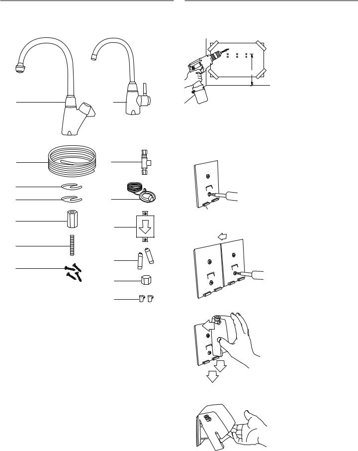
Standard or tall neck faucet
Parts Supplied
|
1 |
or |
|
model WHAB-6014 |
model WHAB-6012 |
|
model WHAB-6015 |
model WHAB-6013 |
|
2 |
8 |
|
3 |
|
|
4 |
9 |
|
5 |
10 |
|
|
|
|
6 |
|
|
|
11 |
|
7 |
|
|
|
12 |
|
|
13 |
1. |
Faucet |
8. ‘’T’’ water line connector |
2. 8 feet of white tubing |
9. Flow monitor indicator ring |
|
3. |
1 rubber washer |
and switch |
4. |
1 metal retaining bracket |
10. Flow monitor |
5. |
1 retaining nut |
11. 2 AA batteries |
6. |
1 threaded rod |
12. Cap |
7. 4 Phillips screw |
13. 2 wall mounting clips |
|
Install the Filterhead Valve
and Filter Cartridge
A B C
unit unit unit
14”
1.Determine the cartridge installation location on the wall under the sink. The mounting template is to help you to locate the mounting bracket. Keep in mind that the center of the top holes on the mounting template must be at least 14’’ (35.6 cm) from the bottom of the under sink cabinet. Position the mounting template securely with tape. Once template is level, drill the guide holes.
NOTE: Be careful not to drill into plumbing or wiring inside the wall.
2.Using 2 Phillips head screws provided, mount 1 bracket to wall (position on left for Unit A).
Tabs must be
located at the bottom.
1
2
3 Click
3.Mount Unit B mounting bracket to wall, to the immediate right of Unit A bracket. The brackets should interlock with each other.
4.Press filterhead valve firmly against the top of the mounting bracket.
Pressing firmly, slowly slide the filterhead valve downwards until both the top and bottom tabs are secure.
Slide the filterhead valve to the center of the mounting bracket. (You should hear a slight click when filterhead valve is secure).
5.Make sure filterhead valve is open by pulling up on the center front.
8
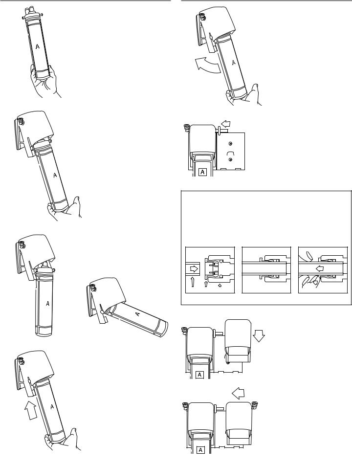
FRONT
FRONT
6.Grasp the base of the filter cartridge with the word “Front” facing you.
9.Push back on a downward arc until the filter cartridge stops.
FRONT
7.Lay the filter cartridge into the filterhead valve cradle.
FRONT
FRONT
10.Place the connector tube into the blue collet “water out” on the right side of the first assembled filterhead valve.
FRONT
FRONT
FRONT
FRONT
FRONT
IMPORTANT:
Do not install the filter cartridge as shown below.
FRONT
8.Push filter catridge up into the filterhead valve until it stops. The 2 colorstrips should be aligned (one in the filterhead valve cradle and one in the filter cartridge).
How to insert tubing in easy to connect fitting
Insert the tubing squarely. See figure A.
Make sure to insert tube completely. See figure B. Push in collet while removing tube. See figure C.
Tube |
Collet |
Body |
Figure A |
Figure B |
Figure C |
11. Take the “B” filterhead valve and place it at the top right of
1 the mounting bracket. Pressing the filterhead valve firmly against the mounting bracket, slide the unit downwards securing both the top and bottom tabs.
12. Slide the “B” filterhead valve to the left, making sure the
2
connector tube goes into the “B” filterhead valve white collet “water in”. Slide to the left until it is centered on the second mounting bracket. (You should hear a slight click, when “B” filterhead valve is secure).
If you do not install the filter C, put the elbow fitting with the blue collet into “B” filterhead valve blue collet “water out”.
13. Repeat step 5 to install filter B.
9
|
|
|
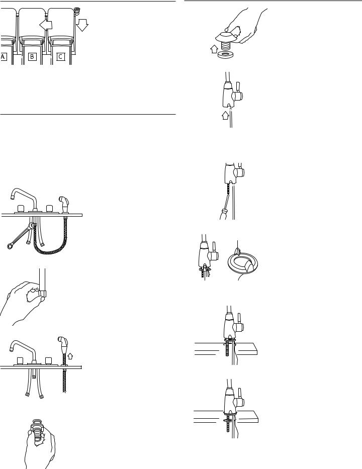
14. If you install filterhead valve C, |
4. Remove hose guide and |
|
Click |
|
repeat steps 2 to 7. If you do |
gasket from sink hole. |
2 |
1 |
not install filterhead valve C |
|
|
|
|
|
(WHAF-0435AC), go to “Install |
|
|
|
|
the faucet” section. |
|
NOTE: At this point, you could install the DirectChill™ unit (WHAF-0115AG) and/or the DirectHot™ unit with dual faucet (WHAF-0155AF) sold separately. Please refer to the Use and Care Guides for those specific products.
If you do not install these options, please follow the next steps.
Install the faucet
See the ”Location requirements” and the ”Water supply requirements” section prior to starting the faucet installation.
NOTE: If your existing faucet has a removable sprayer and you would like to install your new UltraEase™ faucet in the sprayer hole, start the installation at step 9. If not, start at step 14.
1. Turn off both hot and cold water supply to your faucet. Disconnect sprayer hose from faucet fitting.
IMPORTANT: Cap the sprayer hose outlet with the included cap. Use seal compound or Teflon® tape to make a water tight seal.
2. Remove sprayer.
3. From under sink, remove locknut of hose guide.
5.With a utility knife, cut the white tubing at 4 feet. Make sure to make a clean cut at a 90° angle.
IMPORTANT: After cutting the tube, squeeze the tubing back to a round shape.
6.Insert the white tubing into the collet at the bottom of the faucet. Make sure if tubing is fully inserted in the collet.
7.Screw the threaded rod into the faucet base with Phillips screwdriver until tight.
Key |
8. Slide the flow monitor indicator |
|
ring up to the base of the |
|
faucet over the 48” tubing and |
|
the threaded rod. |
Make sure the key is inserted into the key slot on the faucet
bottom.
flow monitor indicator ring
9.Place the rubber washer on the sink surface over the hole. Drop the 48” tubing and faucet assembly down into the hole in the sink. Make sure the flow
monitor wire goes in that hole.
10. From below, install the C shape metal retaining plate over the threaded valve.
10
11. Screw on the retaining nut to secure the faucet.
Connect faucet to filters
1. Insert elbow fitting with blue collet into the blue collet flow monitor outlet.
2. Insert the white tubing into 1 


 the blue collet of the elbow of
the flow monitor outlet.
NOTE: If you choose to install the DirectChill™ unit, connect this tubing to the DirectChill™ unit (for more details please refer to the DirectChill™ Use and Care Guide).
2
3. Insert the 12” long white tubing into the white collet of the flow monitor inlet.
4. Connect the other tubing end to the blue collet elbow of the filterhead valve B (or C
if installed).
5. With the 2 Phillips head screws, install the flow monitor to the cabinet wall.
6.Connect the flow monitor wire to the faucet flow monitor by inserting the connection plug into the flow monitor inlet.
7.Remove screw from cover and install 2 AA batteries in the flow monitor. Replace cover and screw.
8.Disconnect the cold water line to your sink faucet.
9.Install T-fitting included. Use seal compound or Teflon® tape.
10.Cut the white tubing to fit the required installation location. Push white tubing into easy to connect port of T-fitting. Connect the other end to
the filterhead valve elbow fitting of filterhead valve A (white collet).
11.Double check all connections by pulling gently on each portion of tubing.
11
 Loading...