


WDF550SAHB0
Whirlpool WDF550SAHB0, WDF550SAHS0, WDF550SAHW0, WDF518SAHW0, WDF518SAHM0 Installation Guide
...
INSTALLATION INSTRUCTIONS
UNDERCOUNTER DISHWASHER
LAVAVAJILLAS EMPOTRADA CON TINA
INSTRUCTIONS D’INSTALLATION
LAVE-VAISSELLE ENCASTRÉ
Table of Contents ........................................................2
........................................................................21
Indice
Table des matières
....................................................40
W11160365C

TABLE OF CONTENTS
DISHWASHER SAFETY ................................................... 3
INSTALLATION REQUIREMENTS ................................... 4
Tools and Parts ......................................................................... 4
18" Product and Cabinet Opening Dimensions ........................6
24" Product and Cabinet Opening Dimensions ........................7
Location Requirements .............................................................8
Drain Requirements ..................................................................8
Water Supply Requirements .....................................................8
Electrical Requirements ............................................................8
INSTALLATION INSTRUCTIONS ..................................... 9
Prepare Cabinet Opening—NewUtilities ..................................9
Moisture Barrier—Recommended for Wood Countertops .......9
Direct Wire Routing .................................................................10
Prepare Dishwasher ................................................................10
Remove Access Panel ............................................................ 11
Connect Elbow to Valve ..........................................................11
Connect Fill Hose to Elbow ....................................................11
Power Cord Connection .........................................................12
Utility Routing Channel Location ............................................13
Choose Anchor Attachment Method ...................................... 14
Direct Wire Electrical Connection ...........................................17
Connect Water Line to House Shutoff Valve...........................18
Connect Drain Hose ...............................................................18
Complete Installation .............................................................. 20
Reinstall Access Panel ............................................................20
Check Operation ..................................................................... 20
If Dishwasher Does Not Operate ............................................ 20
Additional Tips ........................................................................ 20
2
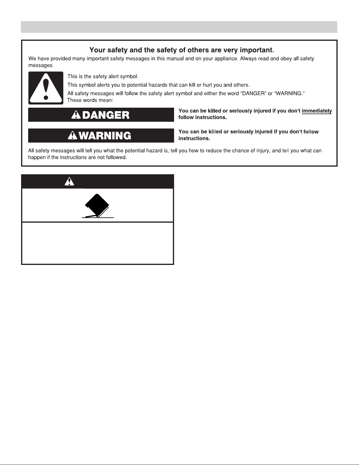
DISHWASHER SAFETY
WARNING
Tip Over Hazard
Do not use dishwasher until completely installed.
Do not push down on open door.
Doing so can result in serious injury or cuts.
You Need to:
■ Slowly open dishwasher door while someone grasps the rear
of the dishwasher. Remove shipping materials and drainhose.
Close dishwasher door until latched.
NOTE: Each dishwasher is tested at the factory and may
contain some residual water in the tub as a result of the test.
■ Observe all governing codes and ordinances.
■ Install this dishwasher as specied in these instructions.
■ Installation should be performed by a qualied servicetechnician.
■ The dishwasher must be installed to meet all electrical
andplumbing national and local codes and ordinances.
Care shall be exercised when the appliance is installed
orremoved, to reduce the likelihood of damage to the
powercord.
WARNING: To reduce the risk of electric shock, re, or injury
to persons, the installer must ensure that the dishwasher is
completely enclosed at the time of installation.
3
INSTALLATION REQUIREMENTS
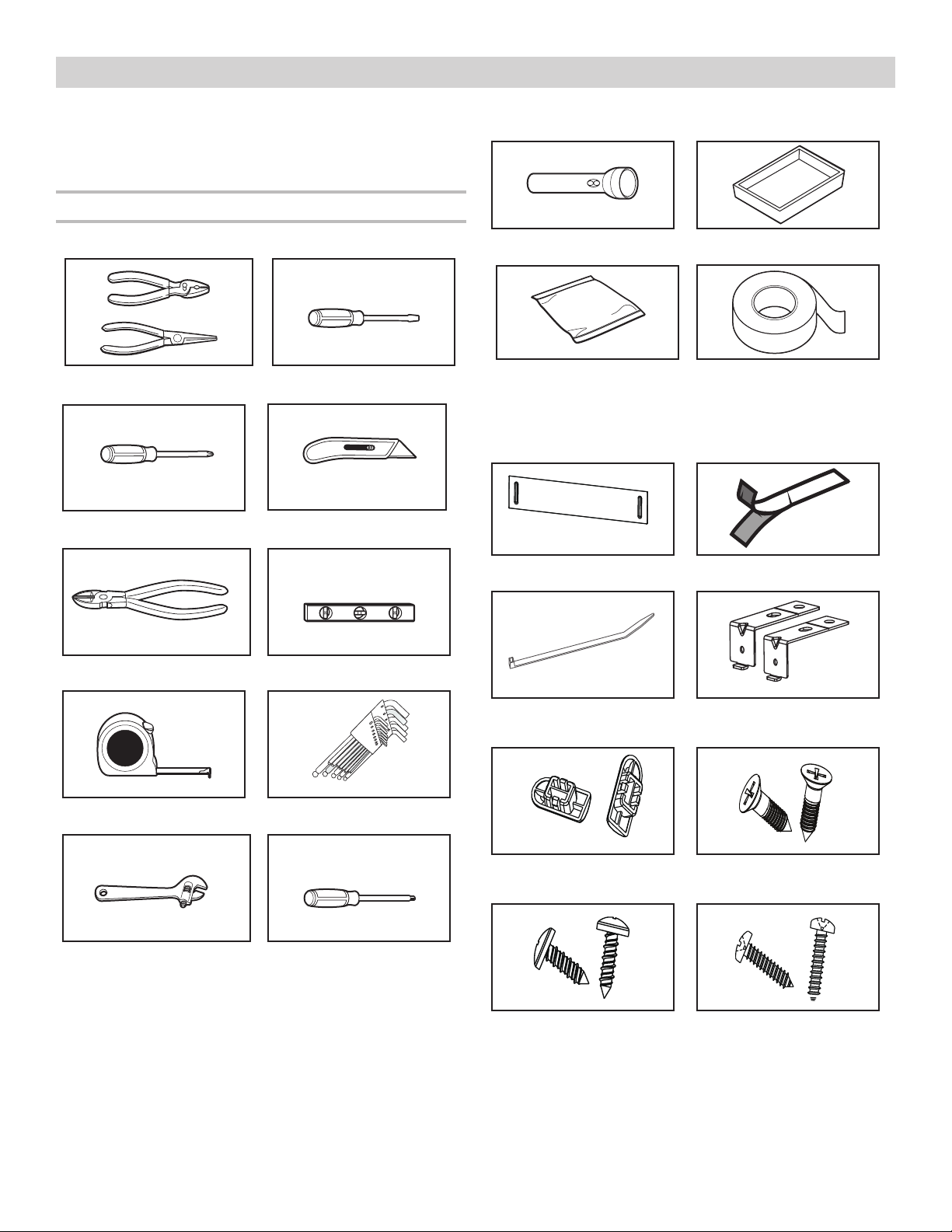
TOOLS AND PARTS
Gather the recommended tools and parts before starting
installation. Read and follow the instructions provided with
thetools listed here.
All Installations
Tools Needed:
Pliers Flat-blade screwdriver
Phillips screwdriver Utility knife
Other Useful Items You May Need:
Flashlight Shallow pan
Bath towel Masking, electrical,
or duct tape
Parts Supplied:
Provided with the dishwasher. Check when you unbox the
dishwasher.
Nipper Small level
Measuring tape or ruler Hex L-wrenches
10" adjustable wrench that
opens to 1
1
/8" (29 mm)
®†
T20® screwdriver
Torx
Kick plate
Cable tie
(for drain hose)
Adjustment cap (2) ST4 x 14(2)
Moisture barrier strip
Undercounter mounting
brackets (2)
(for installation bracket)
†®TORX, T15, and T20 are registred trademarks of Acument Intellectual Properties, LLC.
4
ST3.9 x 9(2)
(for installation bracket)
Make sure all parts are included in the literature package.
If parts are not included, call us at our toll-free number or visit
our website listed in the User Guide.
ST3.9 x 13(2) (for kick plate)
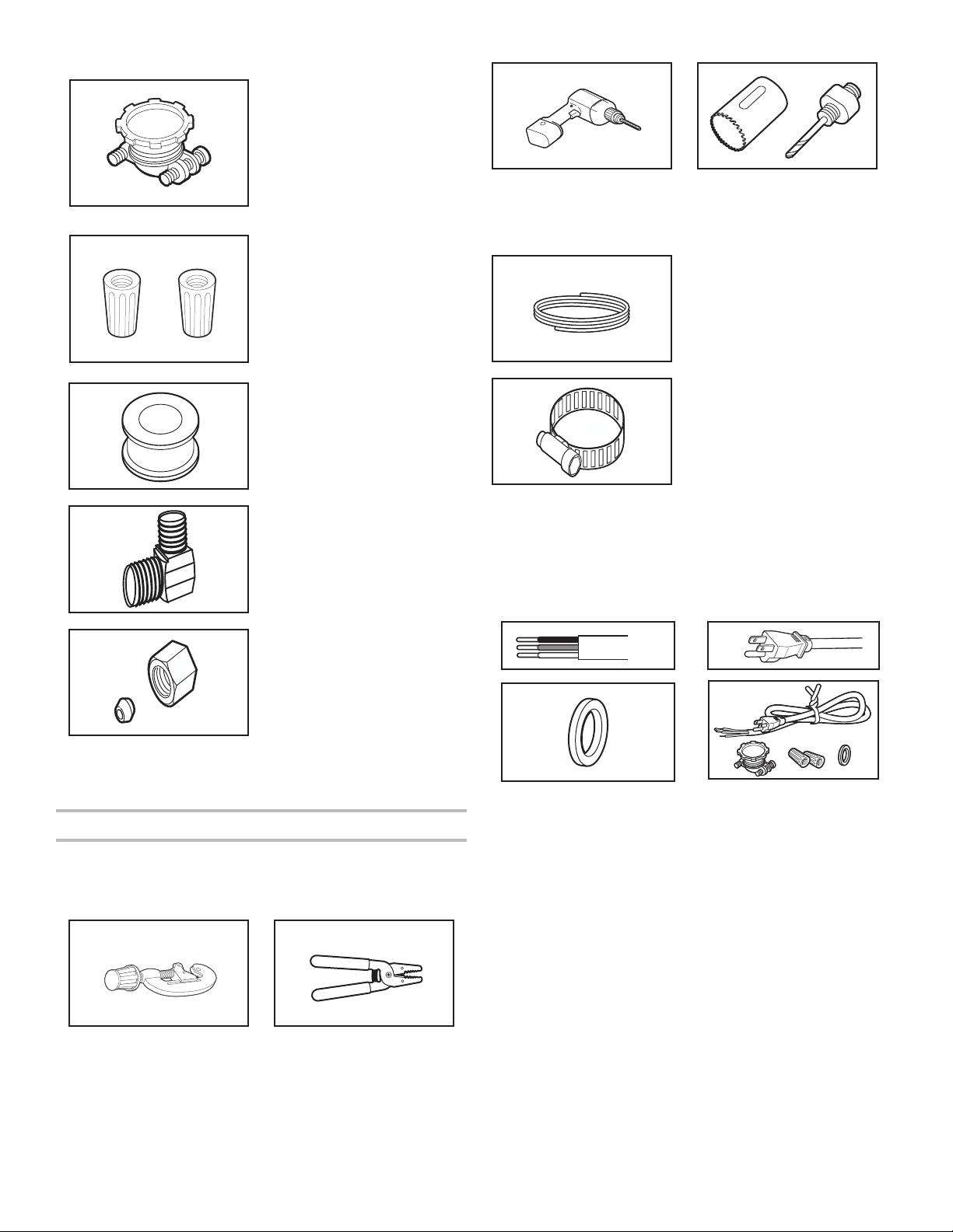
Other Parts Needed (not provided):
Household Wiring (Metallic)
Strain Relief
to t 7/8" (22mm) hole
(required to properly secure
household wiring to the
dishwasher terminal box)
(Whirlpool Part
Number 4396672)
NOTE: Use only UL Listed/
CSA Approved part.
Twist-On Wire Connectors
NOTES:
■ Conrm proper size for
■ Use only UL Listed/CSA
TEFLON®† Tape or Sealing
Compound
connecting your gauge
of household wiring to
the 16-gauge wiring in
the dishwasher.
Approved parts.
Cordless drill 1/2", 3/4", and 11/2" hole
saw bits
Additional Parts Needed (not provided):
Copper Tubing (3/8" O.D.
suggested) or Flexible
Braided WaterSupply
Line Kit (Whirlpool Part
Number W10278635RP).
Kitincludes braided hose
and 3/8" compression x
3/4"hosetting.
Hose Clamps 11/2"- 2"
(38-50 mm) (3maximum)
90° elbow
Tube ttings
(for copper tubing)
Call us at our toll-free number, visit our website listed in the
User Guide for part numbers above, orsee local electrical/
plumbing supply retailer for equivalent.
First-Time Installations
Check local codes. Check existing electrical supply. See the
“Electrical Requirements” section. It is recommended that
electrical connections be made by a licensed electrical installer.
Additional Tools Needed:
Call us at our toll-free number, visit our website listed in the
User Guide for part numbers above, orsee local plumbing supply
retailer for equivalent.
NOTE: If using a exible braided hose, replace inlet hose after
5years to reduce the risk of hose failure. Record hoseinstallation
or replacement dates on the hose for futurereference.
For Direct Wire For Power Cord
Cabinet G
For 11/2" (38 mm) hole
in cabinet. (Whirlpool
PartNumber302797)
NOTE: Required for metal
cabine
Call us at our toll-free number, visit our website listed in the User
Guide for part numbers above, orsee local electrical supply
retailer for equivalent.
ts
rommet
Power Cord Ki
t
Kit typically includes
power cord, metallic strain
relief,grommet, and twist-on
wi
re connectors. (Whirlpool Part
Number 4317824)
Small tubing cutter Wire stripper
†®TEFLON is a registered trademark of Chemours.
5
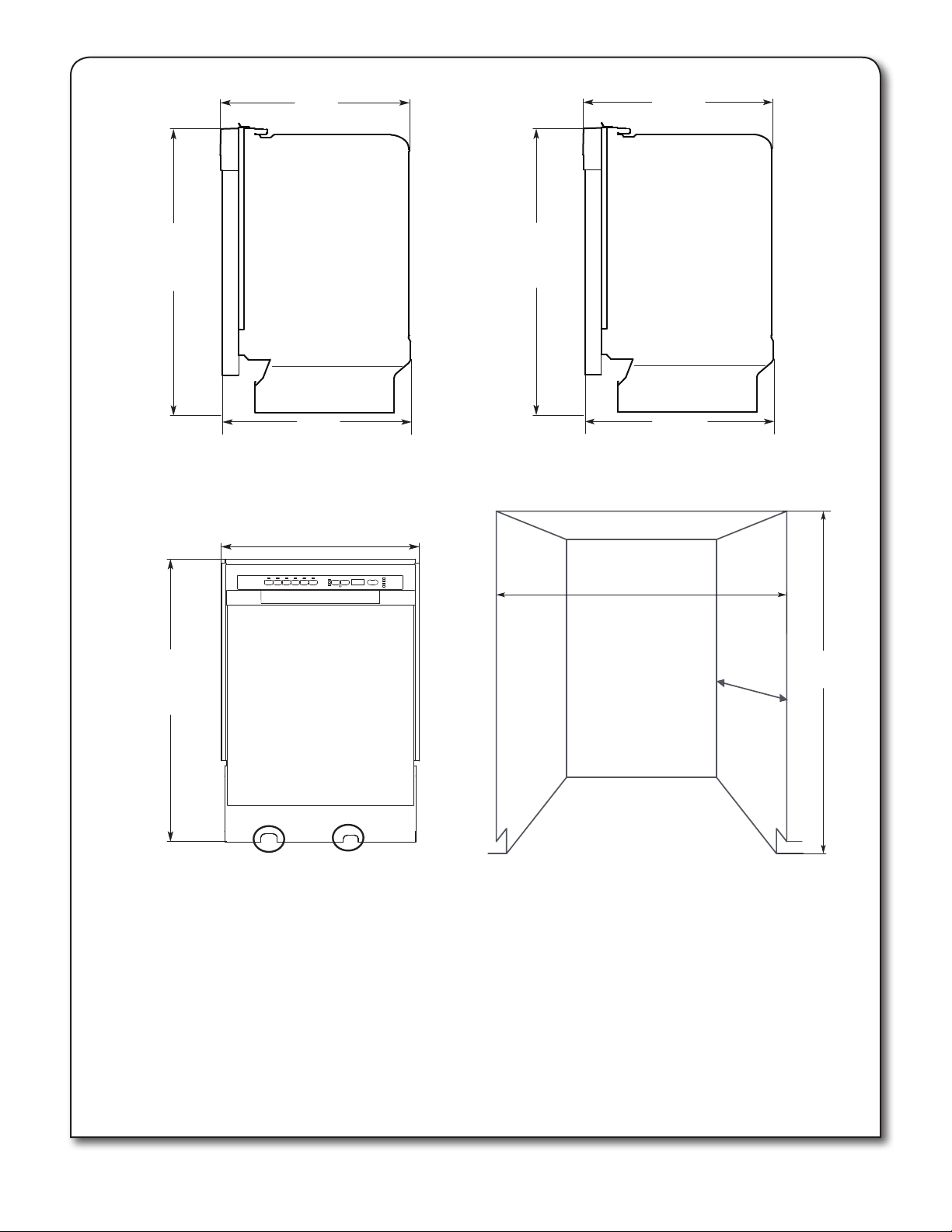
18" PRODUCT AND CABINET OPENING DIMENSIONS:
21 5/8"
(55.0 cm)
22 7/16"
(57.0 cm)
321/2"
(82.5 cm) min.
341/2"
(87.5 cm) max
21 9/16"
(54.7 cm)
Side View 18" Custom Wood Panel
17 5/8"
(44.7 cm) max
32 1/2"
(82.5 cm) min.
34 1/
(87.5 cm) max
2"
321/2"
(82.5 cm) min.
"
341/2
(87.5 cm) max
Side View 18" Metal Door Panel
22 5/16"
(56.6 cm)
18"
(45.7 cm) min.
24"
(61 cm)
min.
1
/2"
32
(82.5 cm) min.
Front View
NOTE: Route the water supply line and power cable through
the channels provided under the dishwasher (circled above).
6
Cutout Dimensions
Underside of countertop to oor
The enclosure must be at least 18" (45.7 cm) wide, 24"
(61 cm) deep, and 32½" (82.5 cm) high.
For the front door of the dishwasher to be ush with the
leading edge of the counter top, the counter top must be
at least 24" (61 cm) deep.
This dishwasher is designed to be enclosed on the top and
on both sides by a standard residential kitchen cabinet unit.
The installation enclosure must be clean and free of any
obstructions.
NOTE: ADA installation, 32½" (82.5 cm) beneath 34"
(86.4 cm) high countertops may be accomplished by
adjusting the toekick and leveling legs.
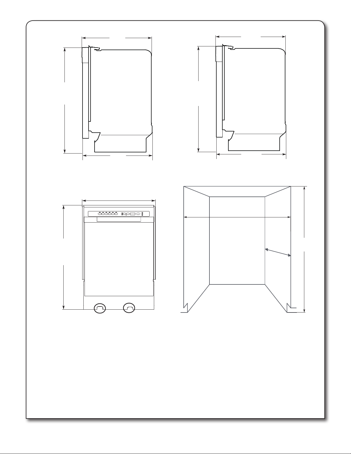
(56.6 cm)
24" PRODUCT AND CABINET OPENING DIMENSIONS:
21 5/8"
(55.0 cm)
22 7/16
(57.0 cm)
"
321/2"
(82.5 cm) min.
341/
(87.
2"
5 cm) max
21 9/16"
(54.7 cm)
Side View 24" Custom Wood Panel
23 1/2"
(59.6 cm)
32 1/2"
(82.5 cm) min.
34
1/2"
(87.
5 cm) max
321/2"
(82.5 cm) min.
2"
341/
(87.5 cm) max
Side View 24" Metal Door Panel
22 5/16"
24"
(61 cm) min.
24"
(61 cm)
min.
1
/2"
32
(82.5 cm) min.
Front View
NOTE: Route the water supply line and power cable through
the channels provided under the dishwasher (circled above).
Cutout Dimensions
Underside of countertop to oor
The enclosure must be at least 24" (61 cm) wide, 24" (61 cm)
deep, and
For the front door of the dishwasher to be ush with the
leading edge of the counter top, the counter top must be
at least 24" (61 cm) deep.
This dishwasher is designed to be enclosed on the top and
on both sides by a standard residential kitchen cabinet unit.
The installation enclosure must be clean and free of any
obstructions.
NOTE: ADA installation, 32½" (82.5 cm) beneath 34" (86.4 cm)
high countertops may be accomplished by adjusting the toekick
and leveling legs.
32½" (82.5 cm)
high.
7
LOCATION REQUIREMENTS
Do not run drain lines, water lines or electrical wiring where they
can interfere with or contact dishwasher motors or legs.
The dishwasher installation location must provide clearance
between motors and ooring. Motors should not touch the oor.
Do not install dishwasher over carpeted ooring.
Protect dishwasher and the water lines leading to dishwasher
against freezing. Damage from freezing is not covered by the
warranty.
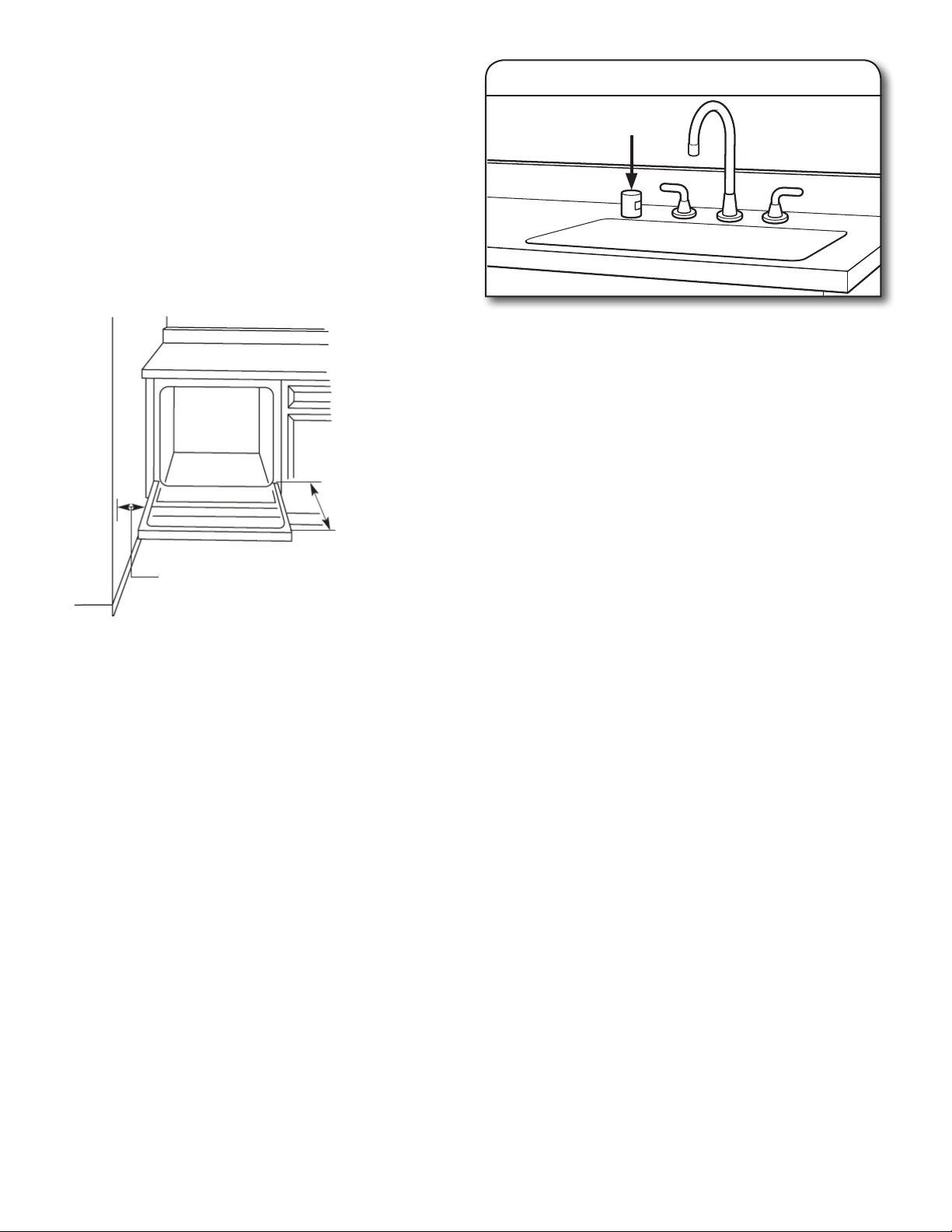
Check dishwasher installation location. The location must provide:
■ Easy access to water, electricity, and drain.
■ Convenient access for loading and unloading dishes. Corner
locations require a 2" (5 cm) minimum clearance between
the side of the dishwasher door and the wall or cabinet.
Use of air gap
Air Gap
■ Use 1/2" (1.3 cm) minimum I.D. drain line ttings.
Countertop
Dishwasher
25 5/8"
(65.1 cm)
2" (5.1 cm) min.
clearance for
door opening
■ Full enclosure on both sides, back, and top.
■ Square opening for proper operation and appearance.
■ Cabinet front perpendicular to oor.
■ Level oor. (If oor at front of opening is not level with oor
at
rear of opening, shims may be needed to level dishwasher.)
NOTE: To prevent shifting during dishwasher operation, shims
must be securely attached to the oor.
If dishwasher will be left unused for a period of time or in a location
where it may be subject to freezing, have it winterized by authorized
service personnel.
Make sure pipes, wires, and drain hose are within the area shown
in the “Cutout dimensions” section.
Helpful Tip: If the oor in the dishwasher opening is uneven,
(example: tile ooring only partway into opening) you will need
to take special care in measuring dimensions and in leveling
dishwasher.
DRAIN REQUIREMENTS
■ Use the new drain hose supplied with your dishwasher. If this
is not long enough, use a new drain hose with a maximum
length of 9.8 ft (3 m) from the sink that meets all current AHAM/
IAPMO test standards, is resistant to heat and detergent.
■ Connect drain hose to waste tee or disposer inlet above the
drain trap in the house plumbing and 20" (50.8 cm) minimum
above the oor. It is recommended that the drain hose be
either looped up and securely fastened to the underside of the
counter, or be connected to an air gap.
■ Use an air gap if the drain hose is connected to house
plumbing lower than 18" (45.7 cm) above the oor.
WATER SUPPLY REQUIREMENTS
■ This dishwasher has a water heating feature and also requires
a connection to a hot water supply line.
■ A hot water line with 20-120 psi (138-862 kPa) water pressure.
■ 120°F (49°C) water at dishwasher.
■ 3/8" (.95 cm) O.D. copper tubing with compression tting or
exible stainless steel braided ll line (1/2" minimum plastic
tubing is not recommended).
■ A 90° elbow with 3/8" (.95 cm) N.P.T. external pipe threads
on one end.
NOTE: Do not solder within 6" (15.2 cm) from ll valve.
ELECTRICAL REQUIREMENTS
Contact a qualied electrician.
Assure that the electrical installation is adequate and in
conformance with all national and local codes and ordinances.
You must have:
■ 120 volt, 60 Hz, AC only, 15 or 20 amp., fused electrical supply.
■ Wiring must be 2 wire with ground.
We recommend:
■ A time-delay fuse or circuit breaker.
■ A separate circuit.
If direct wiring dishwasher:
■ Use exible, armored or non-metallic sheathed, copper wire
with grounding wire that meets the wiring requirements for your
home and local codes and ordinances.
If connecting dishwasher with a power supply cord:
■ Use Power Supply Cord Kit (Part No. 4317824) marked for use
with dishwashers. Kit contents include:
• UL listed 16 gauge 3 wire power supply
cord with 3 prong grounded plug.
• Neer C-500 7/8" (2.2 cm) strain relief.
• 3 wire connectors.
• Part No. 302797 grommet.
Follow the kit instructions for installing the power supply cord.
■ Power supply cord must plug into a mating three prong,
grounded outlet, located in the cabinet next to the dishwasher
opening. Outlet must meet all local codes and ordinances.
8
INSTALLATION INSTRUCTIONS
WARNING
Electrical Shock Hazard
Disconnect electrical power at the fuse box or circuit
breaker box before installing dishwasher.
Failure to do so can result in death or electrical shock.
1. Disconnect power
Disconnect electrical power at the fuse box or circuit
breaker box before installing dishwasher.
2. Shut off water supply
Shut off the water supply to the dishwasher.
PREPARE CABINET OPENING—
NEW UTILITIES
4. Sand holes smooth
Wood
Cabinet
Wood cabinet: Sand the hole until smooth.
Metal cabinet: Cover edges of hole with grommet included with
power cord kit. See the “Tools and Parts” section part details.
Helpful Tip: Wiring the dishwasher will be easier if you route
the cable into the cabinet opening from the right-hand side.
MOISTURE BARRIER - RECOMMENDED FOR
WOOD COUNTERTOPS
Metal
Cabinet
5. Moisture barrier/wood shims
3. Drill hole locations—new construction
Optional
location
11/2"
(38 mm)
NOTE: Refer to the “Product and Cabinet Opening Dimensions”
section for the correct hole placement and dimensions of the
shaded area.
Drill a 1½" (38 mm) drain hose hole in the side or rear of cabinet,
depending on location of drain hose routing and drain hose
connection location.
Drill a 1/2" (12.7 mm) water supply hose hole in the side or rear
of cabinet, depending on location of water supply routing and
connection location
Drill a 1½" (38 mm) electrical conduit hole in the right-hand side
or rear of cabinet.
Preferred
location
1/2"
(12.7 mm)
Moisture
barrier
Make sure the area under the cabinet is clean and dry for
installation of the moisture barrier. Remove the backing of the
moisture barrier, and apply to underside of the countertop along
the front edge of the counter.
9
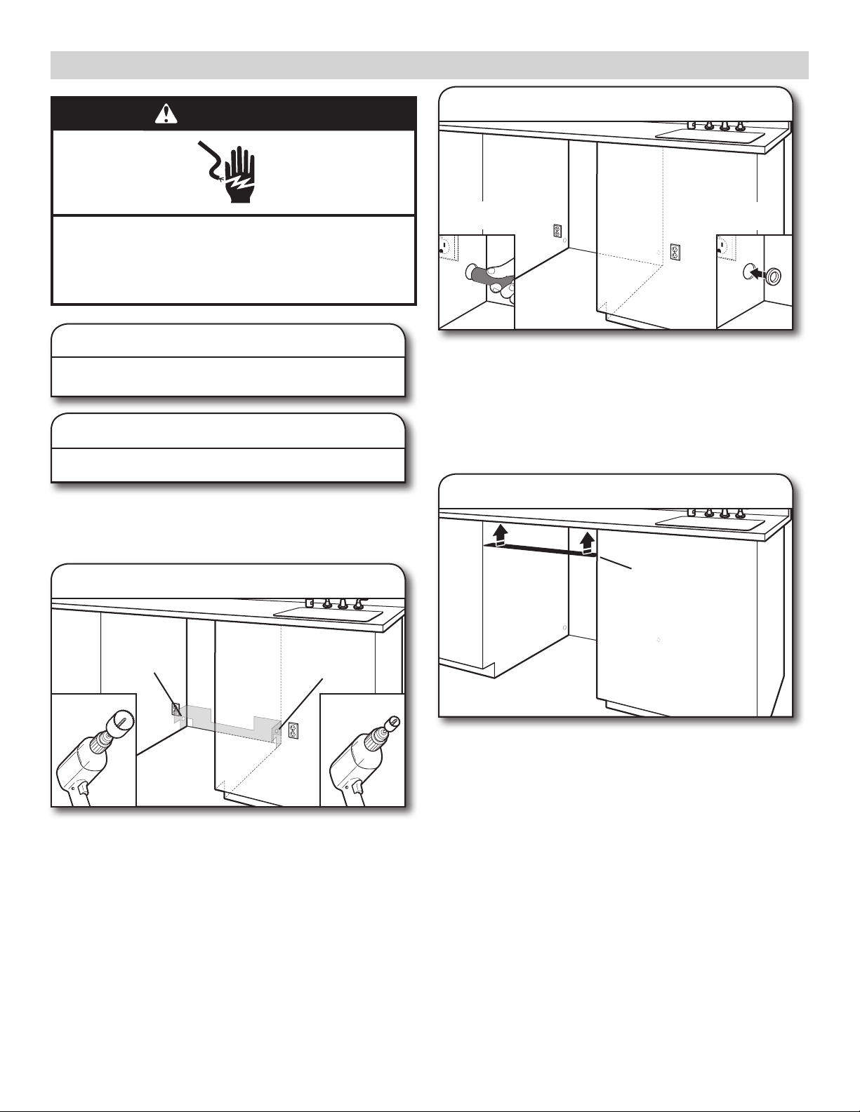
DIRECT WIRE ROUTING
PREPARE DISHWASHER
6. Direct Wire—route cable
Direct wire
location
4"
If direct wire, route the cable 4" (10.2 cm) from the right side of
the cabinet to align with channel in the bottom of the dishwasher.
Tape cable to the oor in the area shown. This will help secure
the cable in place when the dishwasher is moved into the cabinet
opening during direct wire connection.
WARNING
Tip Over Hazard
Do not use dishwasher until completely installed.
Do not push down on open door.
Doing so can result in serious injury or cuts.
WARNING
Excessive Weight Hazard
Use two or more people to move and install
dishwasher.
Failure to do so can result in back or other injury.
7. Put the dishwasher on its back
10
Dishwasher bottom
Helpful Tip: Place cardboard under dishwasher until installed
in cabinet opening to avoid damaging oor covering.
Using two or more people, grasp sides of dishwasher door frame,
and place the dishwasher on its back.
Do not use the door panel as a worktable without rst covering
it with a towel to avoid scratching the door panel.
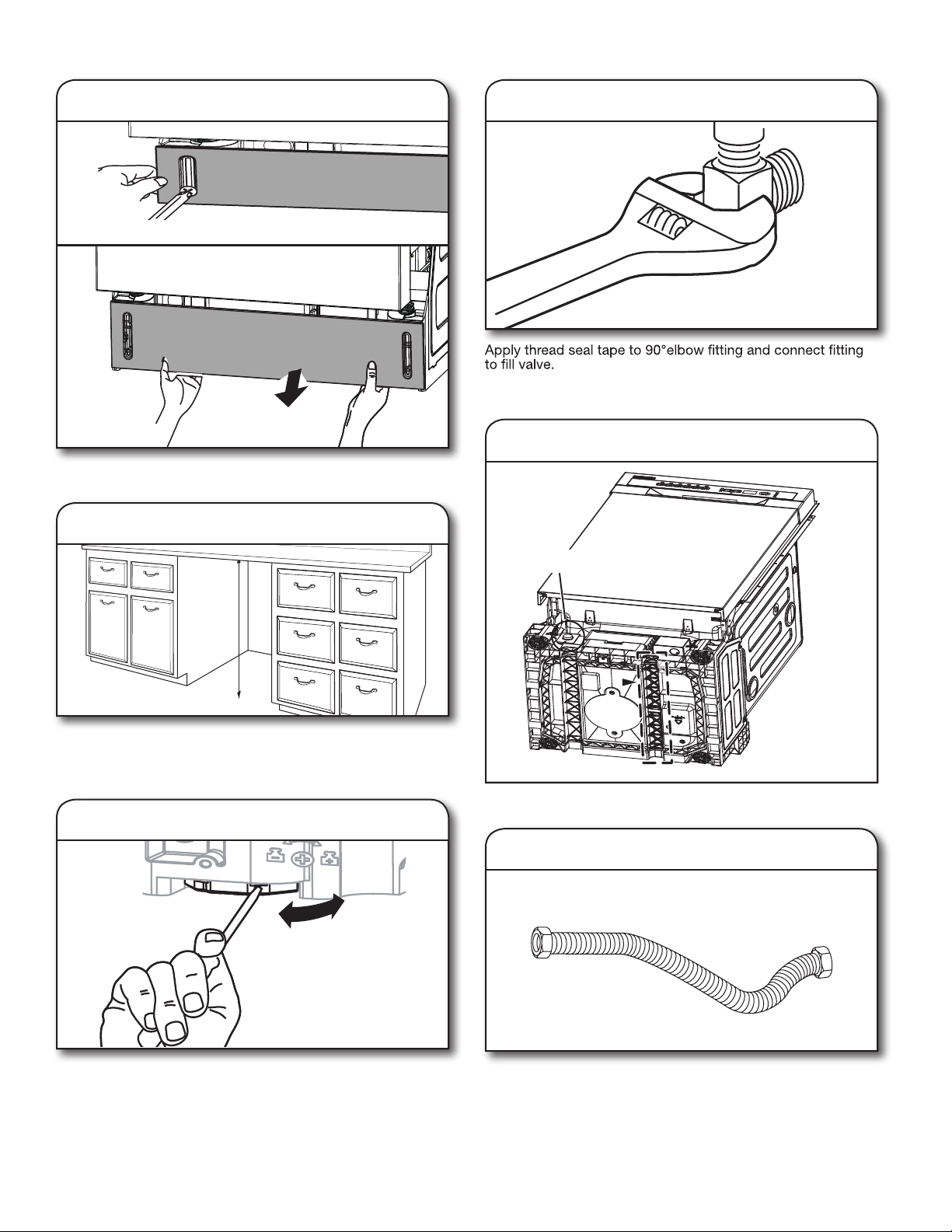
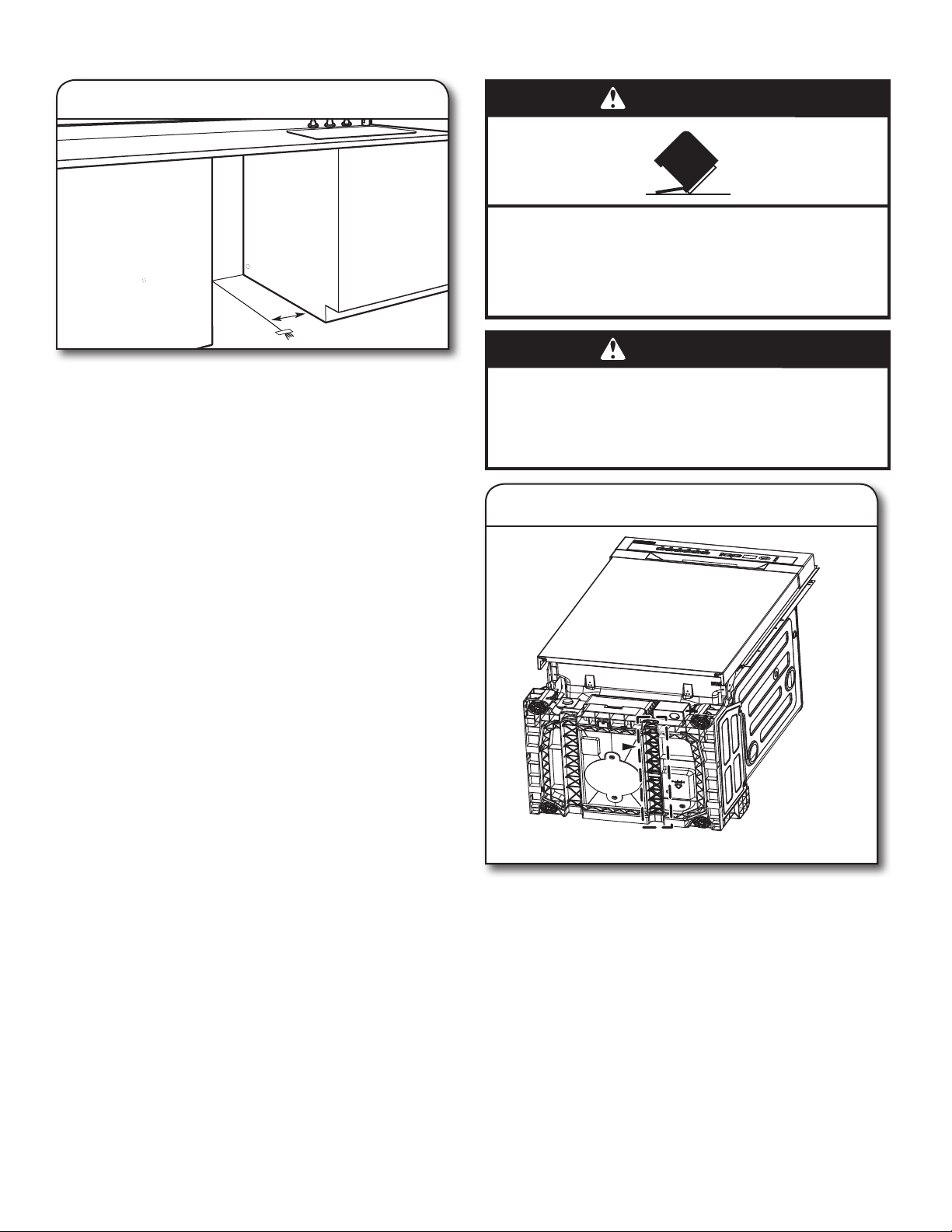
REMOVE ACCESS PANEL
CONNECT ELBOW TO VALVE
8. Remove access panel
Using a 1/4" nut driver or Phillips screwdriver, remove the two
screws attaching access panel to dishwasher.
9. Measure cabinet opening
11. Connect elbow to ll valve
Elbow
Tighten elbow until snug, and be sure that it faces toward
channel in bottom of base.
12. Fill valve location
Measure the height of cabinet opening from the underside of
the countertop to the oor where dishwasher will be installed.
Be sure to measure the lowest point on the underside of the
countertop and the highest point on the oor.
10. Leveling leg adjustment
Fill valve location
CONNECT FILL HOSE TO ELBOW
13. Flexible line
Extend leveling legs out from the dishwasher base, 1/4" less than
the shortest opening height measured in cabinet opening.
Turn leg counter clockwise to raise the dishwasher or clockwise
to lower the diswasher.
Flexible braided line: Conrm the exible braided line is long
enough.
Attach exible line to elbow then route hose out the bottom left
channel under the dishwasher. Secure in channel with tape or
wire ties.
11
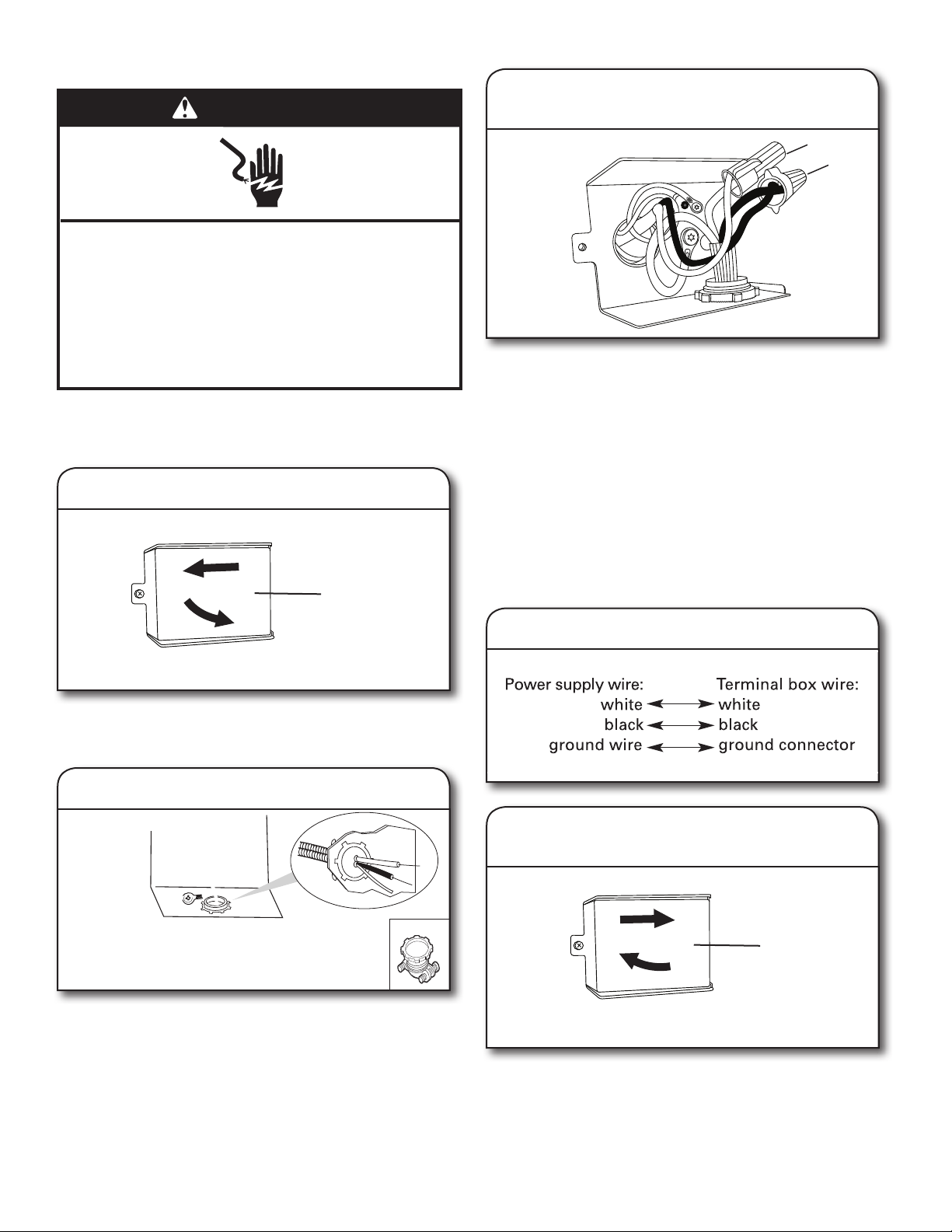
POWER CORD CONNECTION
WARNING
Electrical Shock Hazard
Electrically ground dishwasher.
Connect ground wire to green ground connector in
terminal box.
Do not use an extension cord.
Failure to follow these instructions can result in death,
fire, or electrical shock.
NOTE: If removing a previous dishwasher with a power cord,
you will need to transfer the power cord to the new dishwasher.
14. Remove terminal box cover
Terminal
box cover
16. Power cord—route cord into
terminal box
White
Black
Select UL Listed/CSA Approved twist-on wire connectors of the
proper size. See the “Tools and Parts” section for part details.
Connect wires, black-to-black and white-to-white, using the
twist-on wire connectors.
NOTE: Do not pre-twist stranded wire. Twist on wire connector.
Gently tug on wires to be sure both are secured.
Route cord so that it does not touch dishwasher motor or lower part
of dishwasher tub. Pull cord through strain relief in terminal box.
NOTE: A maximum of two power cord supply conductors
(12 AWG largest size) plus one grounding conductor are
permitted in the terminal box.
Remove the ground connector screw on the raised oor inside
the box and place it through the ring terminal of the green ground
wire of power cord. Reattach and tighten the ground connector
screw to the raised oor of the box. Tighten strain relief screws
to secure cord.
Remove the screw holding the terminal box cover. Remove the
cover by sliding it up and lifting the hooks out of the slot. Keep
the cover for later use.
15. Install strain relief
Install a UL Listed/CSA Approved metallic strain relief. Make
sure screw heads are facing up when tightening conduit nut.
Strain relief is provided with the power cord kit. See the “Tools
and Parts” section for part details and ordering information.
12
Wiring conguration
17. Power cord—reinstall terminal box
cover and wires
Terminal
box cover
Place wires inside terminal box. Replace the cover by inserting
the hooks of the terminal cover into the slots in the oor of the
terminal box and sliding the cover tight against the back wall
where wires come in. Make sure wires are tucked inside the box
and not pinched by the cover.
NOTE: Route power cord out the bottom rear channel provided.
Do not plug cord into an outlet until instructed to do so.
 Loading...